FANUC Series 0i-MODEL C, Series 0i Mate-MODEL C. MAINTENANCE MANUAL - page 9
2. HARDWARE
B-64115EN/02
2.10.1
One battery unit can maintain current position data for six absolute pulse
coders for a year.
Battery for Separate
When the voltage of the battery becomes low, APC alarms 3n6 to 3n8 (n:
Absolute Pulse Coders
axis number) are displayed on the LCD display. When APC alarm 3n7
(6VDC)
is displayed, replace the battery as soon as possible. In general, the battery
should be replaced within one or two weeks, however, this depends on the
number of pulse coders used.
If the voltage of the battery becomes any lower, the current positions for
the pulse coders can no longer be maintained. Turning on the power to
the control unit in this state causes APC alarm 3n0 (reference position
return request alarm) to occur. Return the tool to the reference position
after replacing the battery.
Therefore, FANUC recommends that the battery be replaced once a year
regardless of whether APC alarms are generated.
See Connection Manual
(Hardware)
(B-64113EN) for details of
connecting the battery to separate absolute pulse coders.
Replacing batteries
Obtain four commercially available alkaline batteries (size D).
(1) Turn on the power to the machine (Series 0i/0i Mate).
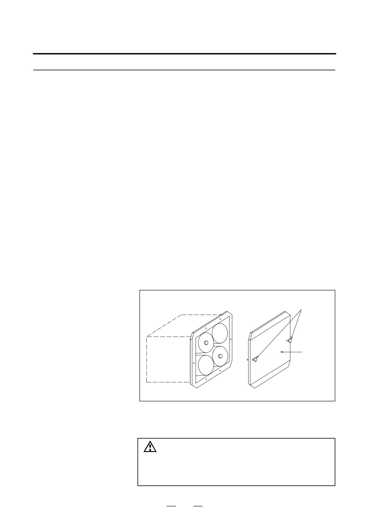
(2) Loosen the screws of the battery case, and remove the cover.
(3) Replace the dry batteries in the case.
Note the polarity of the batteries as shown in the figure below (orient
two batteries one way and the other two in the opposite direction).
Screws
Ÿ
Ÿ
Ÿ
Ÿ
Ÿ
Cover
ŸŸ
Ÿ
Ÿ
Ÿ
(4) After installing the new batteries, replace the cover.
(5) Turn off the power to the machine (Series 0i/0i Mate).
WARNING
If the batteries are installed incorrectly, an explosion may
occur. Never use batteries other than the specified type
(Size D alkaline batteries).
220

2. HARDWARE
B-64115EN/02
CAUTION
Replace batteries while the power to the CNC is on. Note
that, if batteries are replaced while no power is supplied to
the CNC, the recorded absolute position is lost.
2.10.2
The battery for the absolute pulse coder built into the motor is installed
in the servo amplifier. For how to connect and replace the battery, refer
Battery for Absolute
to the following manuals:
Pulse Coder Built into
D FANUC SERVO MOTOR αi series Maintenance Manual
the Motor (6VDC)
D FANUC SERVO MOTOR β series Maintenance Manual
D FANUC SERVO MOTOR β series (I/O Link Option) Maintenance
Manual
221
2. HARDWARE
B-64115EN/02
2.11
REPLACING FAN
WARNING
MOTORS
When opening the cabinet and replacing a fan motor, be
careful not to touch the high-voltage circuits (marked and
fitted with an insulating cover).
Touching the uncovered high-voltage circuits presents an
extremely dangerous electric shock hazard.
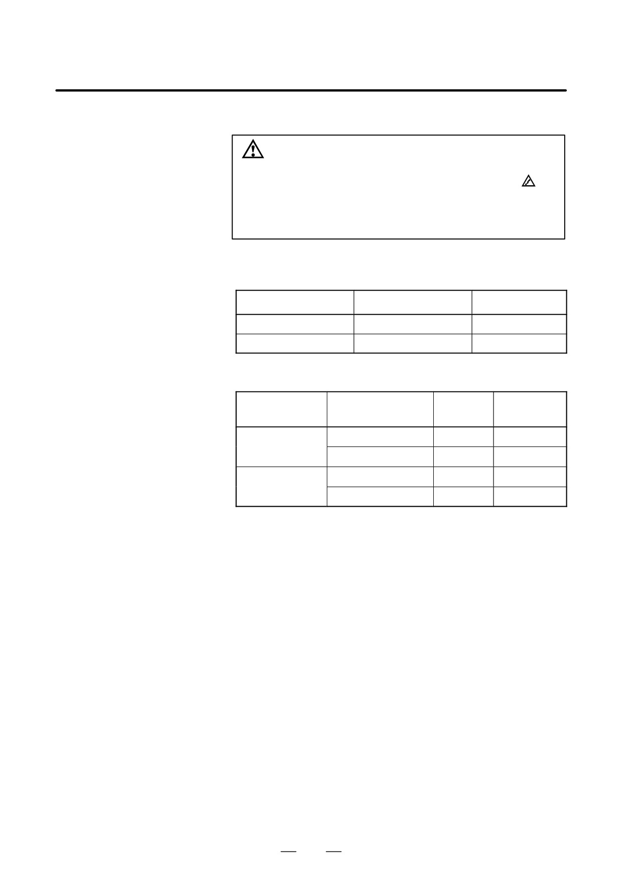
D Fan ordering information
If the drawing number of the basic unit is A02B-0309-B50n,
A02B-0311-B50n, or A02B-0311-B51n (where n is 0, 1, ..., 9)
Ordering information
Required quantity
Unit with no option slot
A02B-0236-K120
2
Unit with 2 option slots
A02B-0281-K121
2
If the drawing number of the basic unit is A02B-0309-B52n,
A02B-0311-B52n, or A02B-0311-B53n (where n is 0, 1, ..., 9)
Ordering information
Mounting
Required
location
quantity
Unit with no option slot
A02B-0309-K120
Right
1
A02B-0309-K120
Left
1
Unit with 2 option slots
A02B-0309-K120
Right
1
A02B-0309-K121
Left
1
222
2. HARDWARE
B-64115EN/02
Replacement procedure
If the drawing number of the basic unit is A02B-0309-B50n,
A02B-0311-B50n, or A02B-0311-B51n (where n is 0, 1, ..., 9)
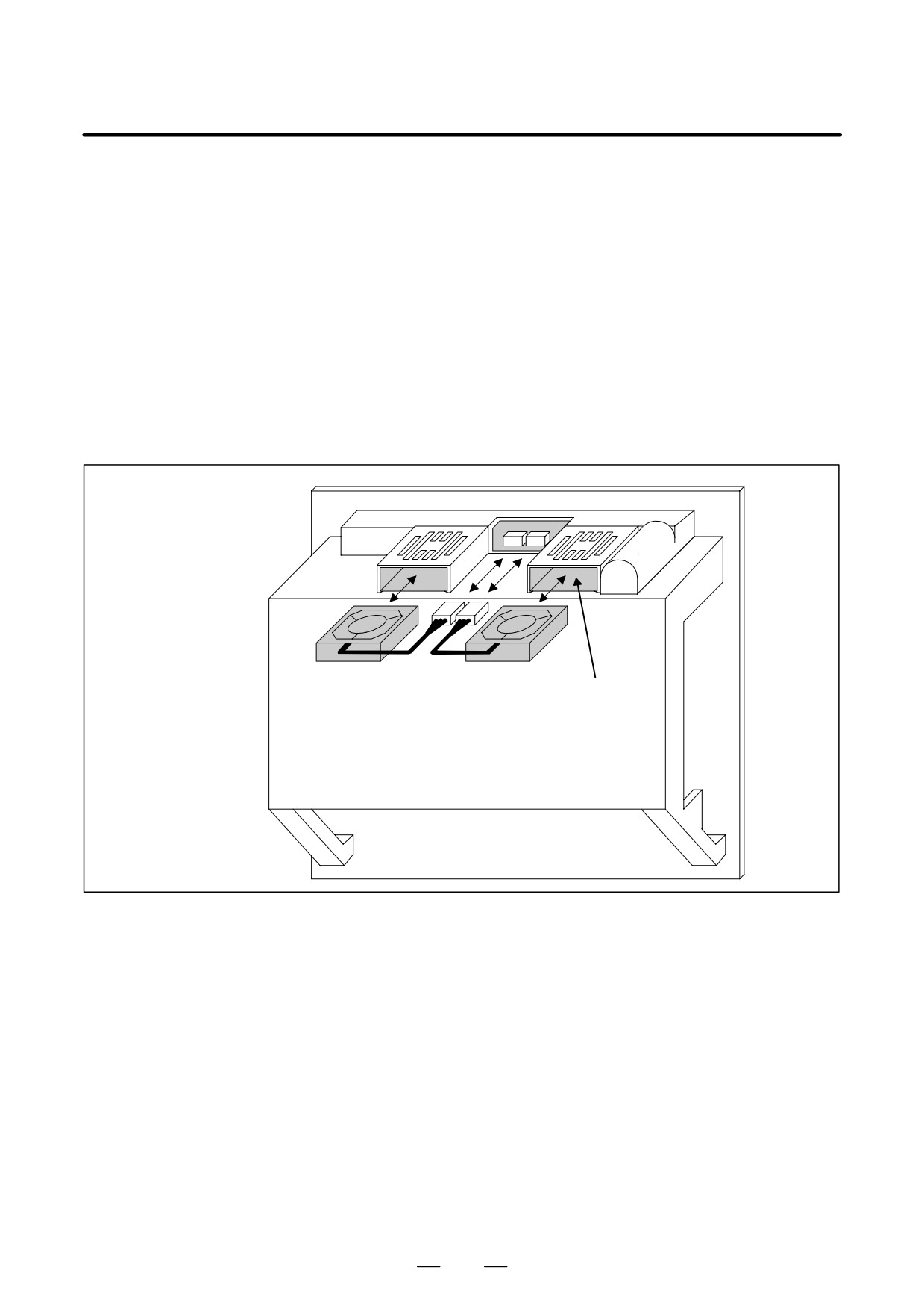
1. Before replacing a fan motor, turn off the power to the CNC.
2. Unplug the connector of a fan motor to be replaced ( (1) of Fig. a).
The connector is latched. So, when unplugging the connector, hold
down the latch placed at the lower part of the connector with a
flat-blade screwdriver.
3. Detach the latch securing the fan motor, then demount the fan motor
( (2) of Fig. a).
4. Insert a new fan motor into the fan case ( (3) of Fig. a), then reconnect
the connector.
Fig. a
(1) Connector
(3) Fan case
(2) Fan
Note) Install a fan so that it flows air in the upward
direction.
(Face the label upward.)
223
2. HARDWARE
B-64115EN/02
If the drawing number of the basic unit is A02B-0309-B52n,
A02B-0311-B52n, or A02B-0311-B53n (where n is 0, 1, ..., 9)
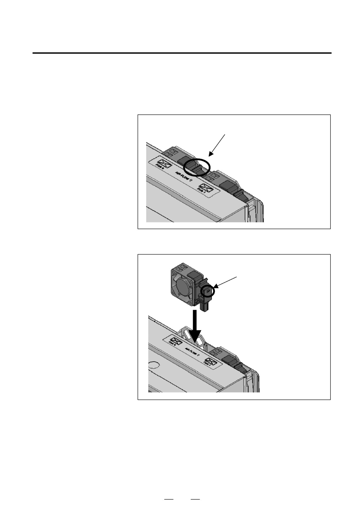
1) Before replacing a fan motor, turn off the power to the CNC.
2) Extract the fan motor to be replaced. (Hold the latch of the fan unit,
and extract the unit upward while releasing the claw from the case.)
Extract the unit while holding
this portion.
3) Mount a new fan unit. (Push the fan unit in until the claw is latched
into the case.)
Push the unit in until the claw
is latched into the case.
224
2. HARDWARE
B-64115EN/02
2.12
REPLACING LCD
WARNING
BACKLIGHT
Only those personnel who have received approved safety
and maintenance training may perform this replacement
work.
When opening the cabinet and replacing a unit, be careful
not to touch the high-voltage circuits (marked
and fitted
with an insulating cover).
Touching the uncovered high-voltage circuits presents an
extremely dangerous electric shock hazard.
CAUTION
Before starting replacement work, back up the contents
(such as parameters and programs) of the SRAM memory
of the CNC. Otherwise, the contents of the SRAM memory
may be lost during replacement work.
Brightness of the
When the ambient temperature is low, the brightness of the LCD
monochrome LCD
decreases.
(The LCD screen is dark particularly immediately after the
power is turned on.) This phenomenon is not a failure but is a property
specific to the LCD. When the ambient temperature increases, the LCD
screen becomes brighter. The monochrome LCD has a brightness control
function. For the method of adjustment, see Section 1.17.
D Backlight ordering
information
Backlight
Ordering information
For 7.2″ LCD
A02B-0236-K112
For 8.4″ LCD
A02B-0236-K119
For 10.4″ LCD
A02B-0309-K116
225
2. HARDWARE
B-64115EN/02
D Replacement procedure
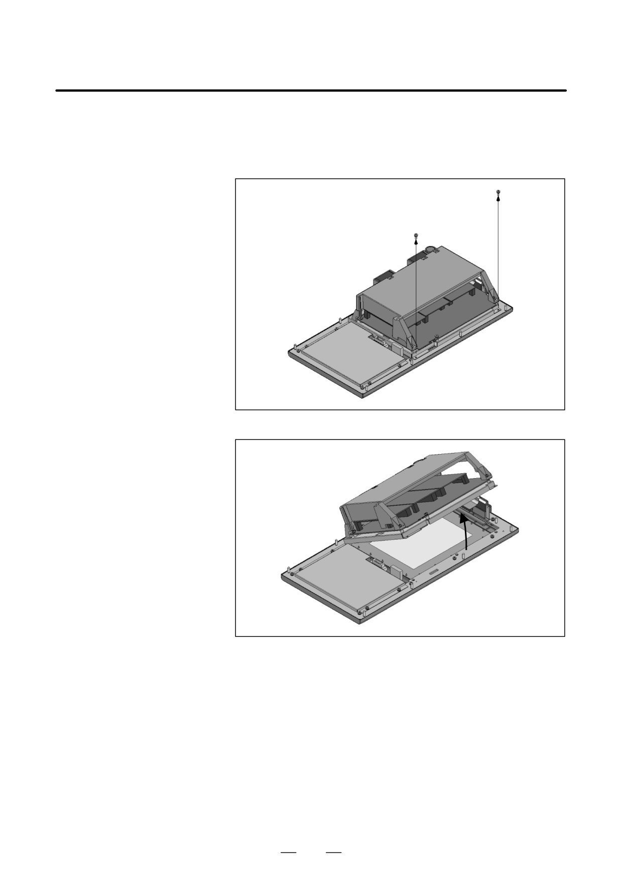
Replacing a horizontal type LCD/MDI unit
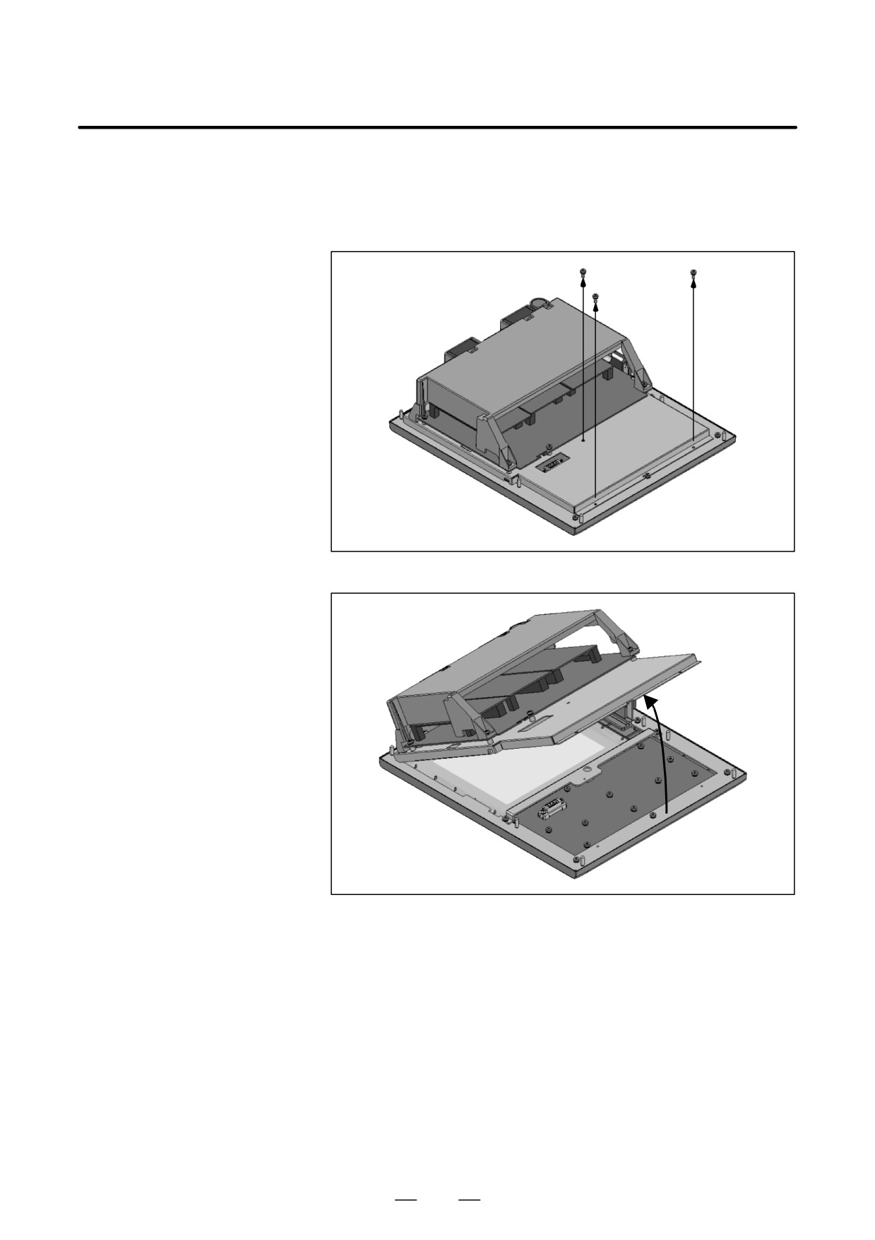
1) Detach the soft key and memory card cables from the main board.
Remove the two screws shown below.
(If it is hard to detach the
memory card cable, detach the basic unit case before it.)
2) Lift the basic unit block by pivoting it on its upper portion.
226
2. HARDWARE
B-64115EN/02
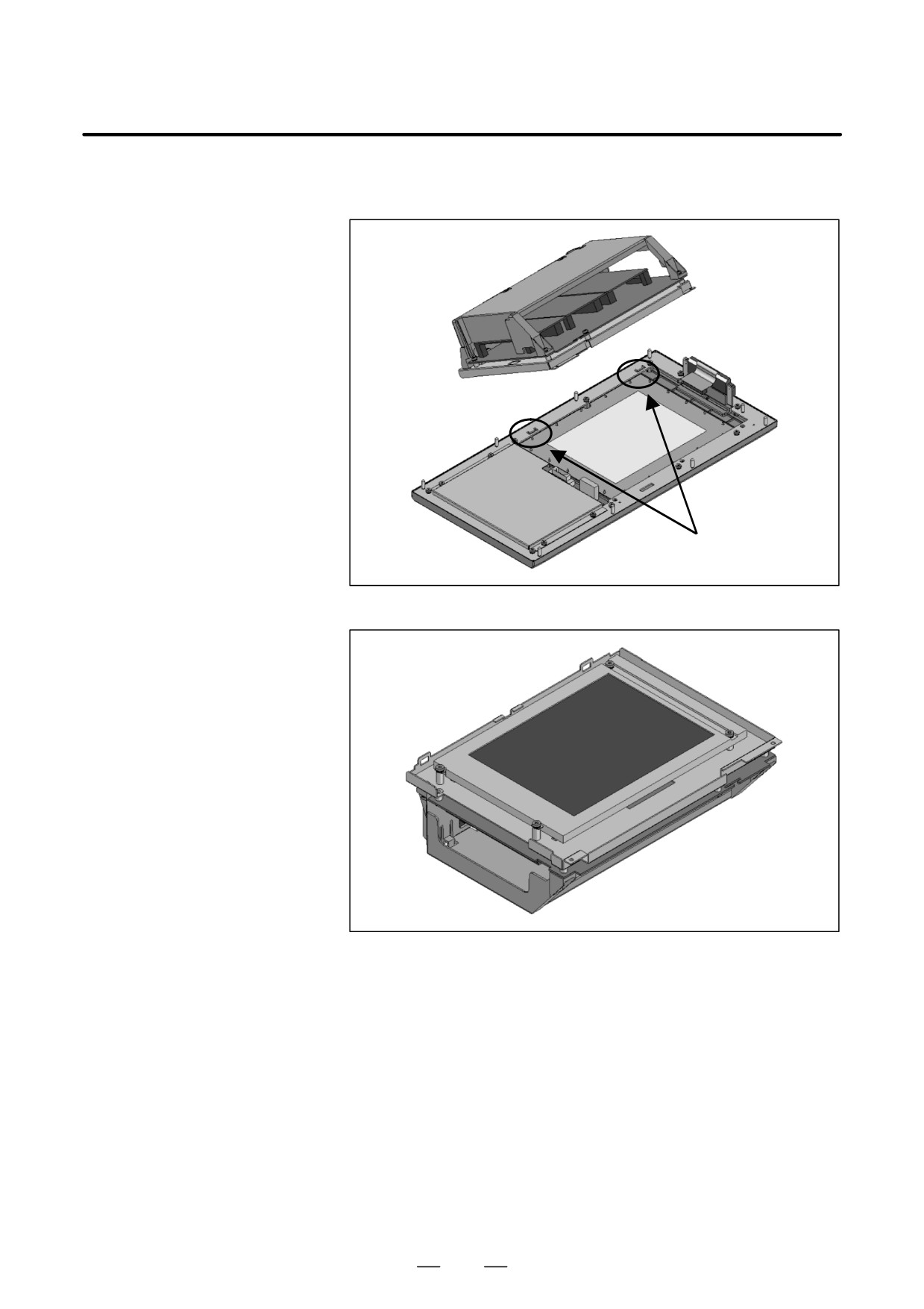
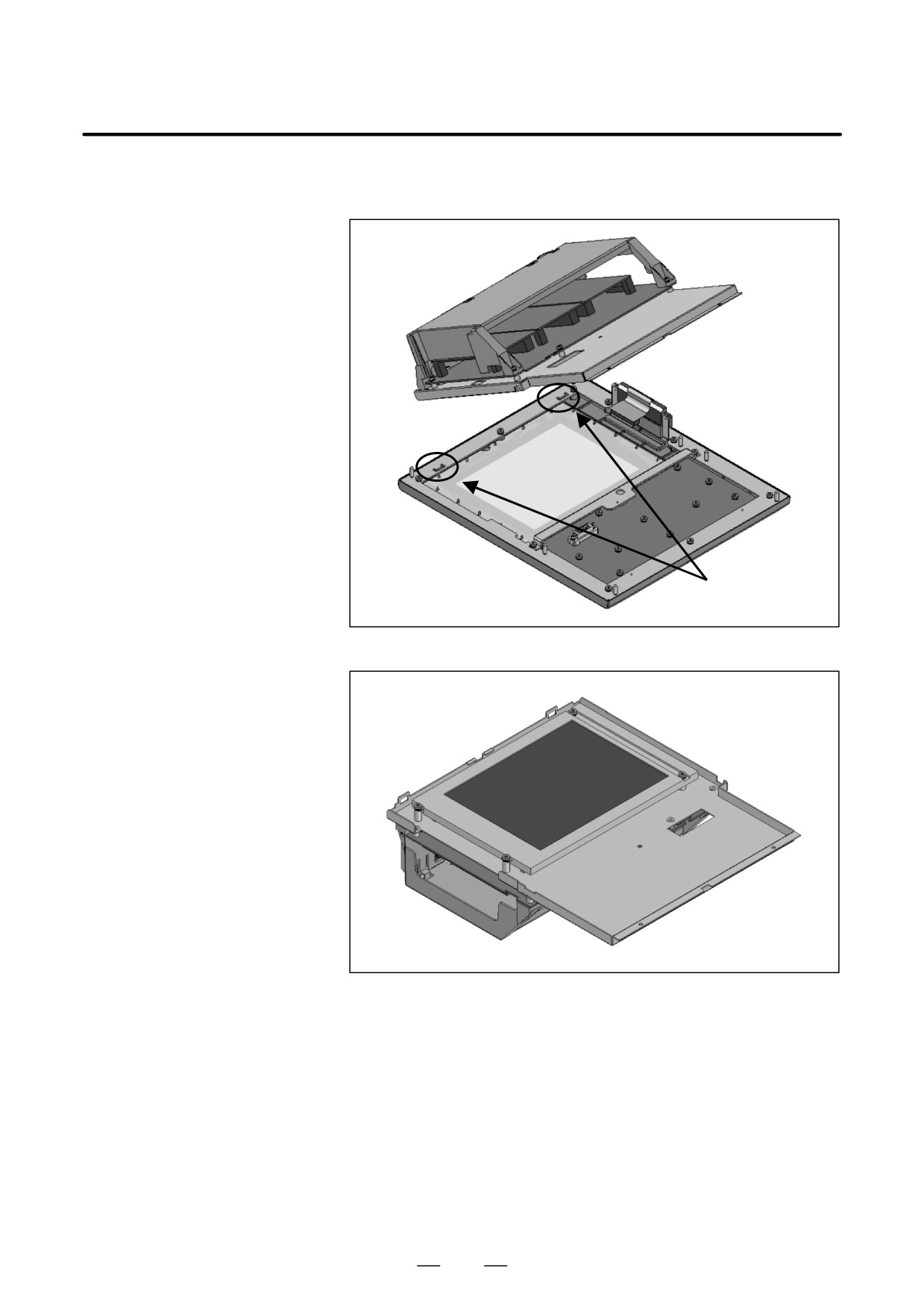
3) Under the condition attained in step 2), slide the basic unit block down
a little and detach it from the notches of the base metal plate.
Notch
4) Turn over the basic unit, and you will see the LCD panel.
227
2. HARDWARE
B-64115EN/02
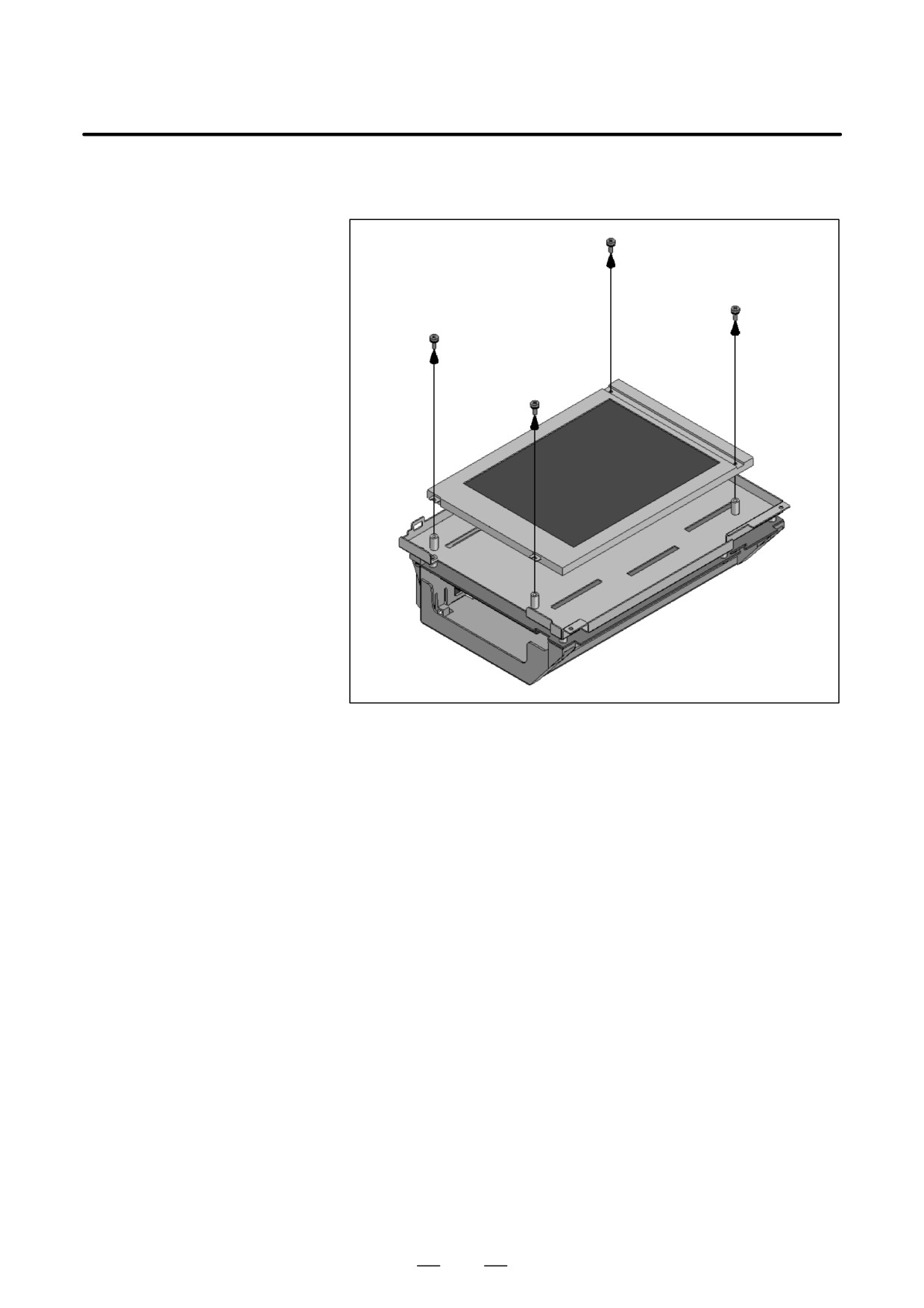
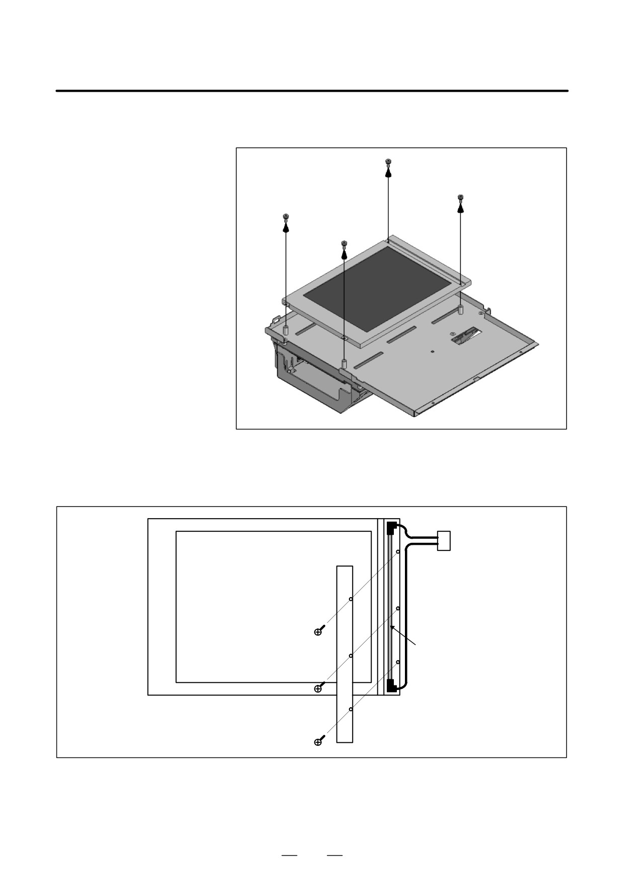
5) Remove the inverter cable and then four fastening screws from the
LCD panel. Now the LCD panel can be detached.
228
2. HARDWARE
B-64115EN/02
Replacing a vertical type LCD/MDI unit
1) Detach the memory card cable from the main board. Remove the
three screws shown below. (If it is hard to detach the memory card
cable, detach the basic unit case before it.)
2) Lift the basic unit block by pivoting it on its upper portion.
229
2. HARDWARE
B-64115EN/02
3) Under the condition attained in step 2), slide the basic unit block down
a little and detach it from the notches of the base metal plate.
Notch
4) Turn over the basic unit, and you will see the LCD panel.
230
2. HARDWARE
B-64115EN/02
5) Remove the inverter cable and then four fastening screws from the
LCD panel. Now the LCD panel can be detached.
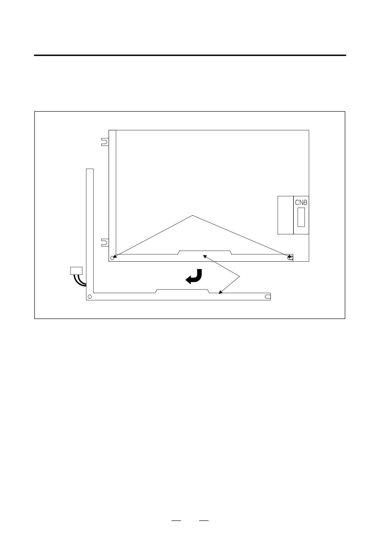
6)-1 For the 7.2″ LCD unit (monochrome)
Remove the three screws from the left part on the front of the LCD
unit, and remove the cover. Then, the backlight is exposed. Replace
the backlight with a new one.
Connector
Display surface of LCD unit
Backlight
231
2. HARDWARE
B-64115EN/02
6)-2 For the 8.4″ LCD (color)
As shown below, remove two bolts, remove the backlight case by
pulling it down and sliding it slightly to the left, then replace the
backlight.
LCD unit rear view
Bolt
Backlight
232
2. HARDWARE
B-64115EN/02
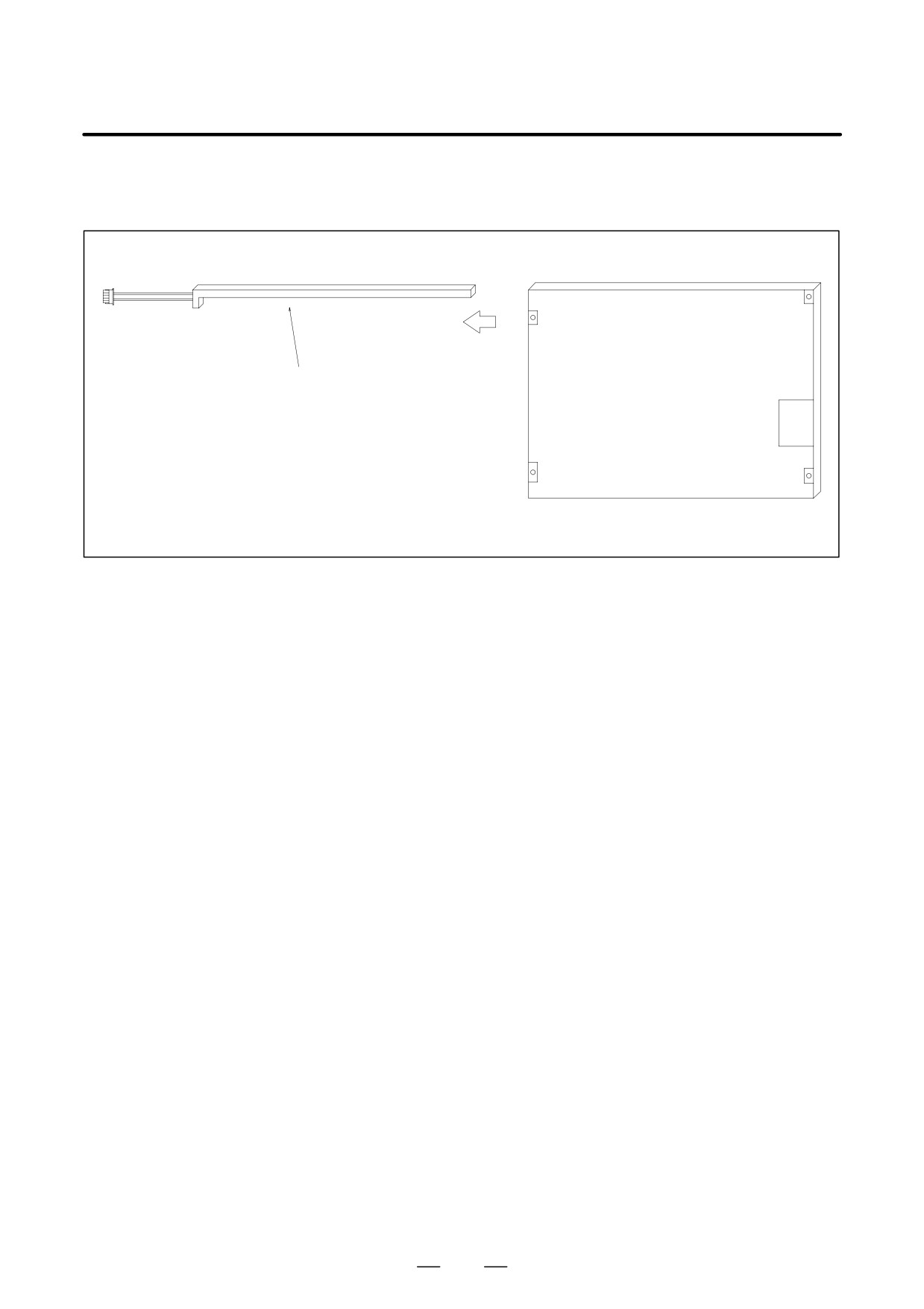
6)-3 For the 10.4″ LCD (color)
Pull out the inverter as shown below.
Backlight
233
2. HARDWARE
B-64115EN/02
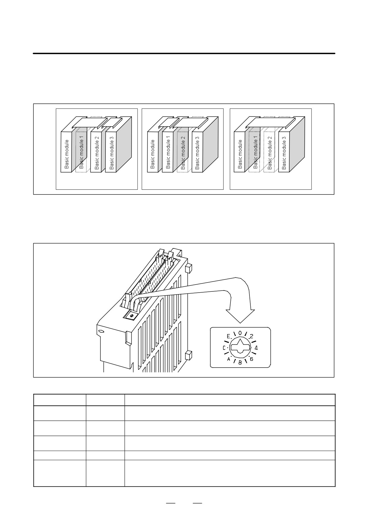
By changing the setting (rotary switch) on an expansion module, a
2.13
connection can be made to skip an expansion module or expansion
DISTRIBUTED I/O
modules as shown below.
SETTING
When expansion module 1 is
When expansion module 2 is
When expansion modules 1 and
skipped
skipped
2 are skipped
Method of setting (control and setting method)
A control (rotary switch) is provided on the location shown below of each
expansion module. When changing the setting, turn the rotary switch
with a flat-blade screwdriver with a tip diameter of about 2.5 mm.
Each setting position of the rotary switch has the meaning as indicated below.
Setting position
Indication
Meaning of setting
0
0
Standard setting. The rotary switch is set to this position at the time of shipment from FANUC.
This setting is not skipped an expansion module.
1
-
Set the rotary switch of an expansion module to this position when the one preceding expansion
module is skipped.
2
2
Set the rotary switch of an expansion module to this position when the two preceding expansion
modules are skipped.
3
-
Setting prohibited
4 to F
4, -, 6, -,
4, 8, or C has the effect of 0.
8, -, A, -,
5, 9, or D has the effect of 1.
C, -, E, -,
6, A, or E has the effect of 2.
7, B, or F has the effect of 3. (← setting prohibited)
234
2. HARDWARE
B-64115EN/02
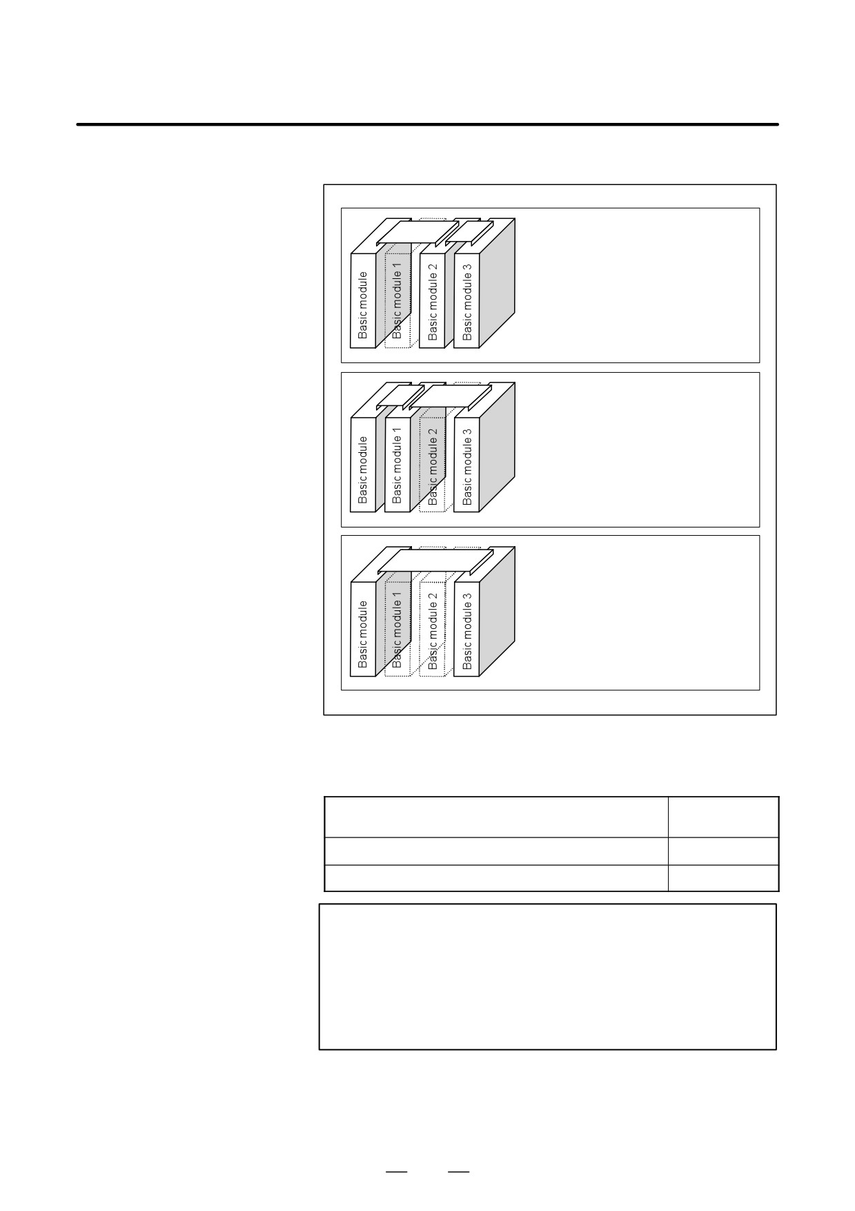
Examples of setting
(When expansion module 1 is skipped)
Set the rotary switch of expansion module 2
to setting position = 1. Do not change the
setting (setting position = 0) of expansion
module 3.
(When expansion module 1 and expansion
module 2 are skipped)
Set the rotary switch of expansion module 3
to setting position = 2.
(When expansion module 2 is skipped)
Set the rotary switch of expansion module 3
to setting position = 1. Do not change the
setting (setting position = 0) of expansion
module 1.
This function was not available initially, but was recently added. This
function became available, depending on the type of module, as indicated
below.
Expansion module B (DI/DO = 24/16, without a manual pulse gen-
A03B-0815-C003
erator interface)
Expansion module C (DO = 16, 24A output)
A03B-0815-C004
Expansion module D (analog input)
A03B-0815-C005
NOTE
To expansion module A (DI/DO = 24/16, with a manual pulse
generator interface) (A03B-0815-C002), a rotary switch is
added as the other modules are modified. However,
expansion module A is always installed at the location of
expansion module 1, so that the setting of expansion
module A need not be changed.
235
2. HARDWARE
B-64115EN/02
2.14
REPLACING FUSES
WARNING
ON VARIOUS UNITS
Before replacement of a blown fuse, the cause of the blown
fuse must be corrected. So, fuse replacement work must be
done only by a person who is trained in the related
maintenance and safety requirements. When opening the
cabinet and replacing a fuse inside, be careful not to touch
the high-voltage circuits (marked with
and fitted with an
insulating cover). Touching the uncovered high-voltage
circuits presents an extremely dangerous electric shock
hazard.
For the specification of the fuse of each unit, see the list of consumables
in Appendix B.
236
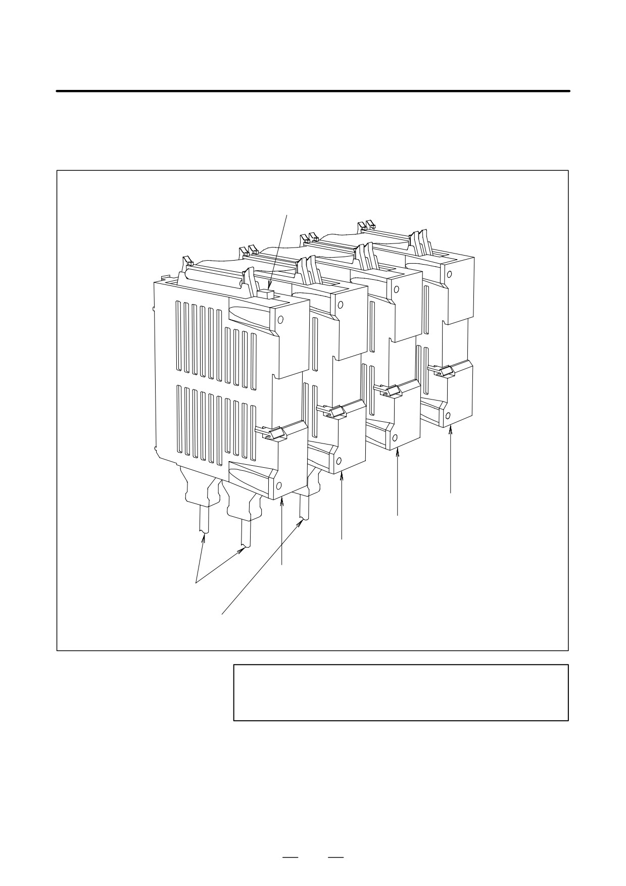
2. HARDWARE
B-64115EN/02
D Fuse mounting location
on the connector panel
I/O modules
Fuse
Expansion module 3
Expansion module 2
Expansion module 1
Basic module
(A03B-0815-C001)
Cable for the I/O Link
(A03B-0815-C051)
Cable for a manual pulse generator
NOTE
No fuse is provided on the expansion modules. A fuse is
provided on the basic module only.
237
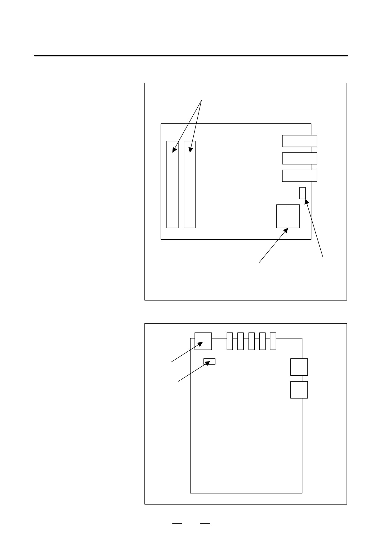
2. HARDWARE
B-64115EN/02
D Fuse mounting location
on the operator’s panel
I/O modules
I/O connector
JD1A
JD1B
JA3
Fuse
Power supply connector
This drawing is for A20B-2002-0470, A20B-2002-0520,
A20B-2002-0521, A20B-2003-0750, and A20B-2003-0751.
D Fuse mounting location
on the separate detector
interface unit
Power
connector
Optical
connector
Fuse
238

2. HARDWARE
B-64115EN/02
The peripheral units and the control unit have been designed on the
2.15
assumption that they are housed in closed cabinets. In this manual
ENVIRONMENTAL
“cabinet” refers to the following:
REQUIREMENTS
D Cabinet manufactured by the machine tool builder for housing the
OUTSIDE THE
control unit or peripheral units;
CONTROL UNIT
D Operation pendant, manufactured by the machine tool builder, for
housing the control unit or operator’s panel.
D Equivalent to the above.
The environmental conditions when installing these cabinets shall
conform to the following table. Section 3.3 describes the installation and
design conditions of a cabinet satisfying these conditions.
Operating
0°C to 58°C
Ambient
Temperature
Storage, Transport
-20°C to 60°C
Temperature
1.1_C/minute (maximum)
change
Normal
75%RH or less, no condensation
Humidity
Short period
95%RH or less, no condensation
(less than 1 month)
Operating
0.5 G or less
Vibration
Non-operating
1.0 G or less
Operating
Up to 1000 m
Meters above
sea level
Non-operating
Up to 12000 m
Normal machine shop environment
(The environment must be considered if the cabinets are in
Environment
a location where the density of dust, coolant, and/or organic
solvent is relatively high.)
239
2. HARDWARE
B-64115EN/02
The CNC has been steadily reduced in size using surface-mount and
2.16
custom LSI technologies for electronic components. The CNC also is
ACTION AGAINST
designed to be protected from external noise. However, it is difficult to
NOISE
measure the level and frequency of noise quantitatively, and noise has
many uncertain factors. It is important to prevent both noise from being
generated and generated noise from being introduced into the CNC. This
precaution improves the stability of the CNC machine tool system.
The CNC component units are often installed close to the parts generating
noise in the power magnetics cabinet. Possible noise sources into the
CNC are capacitive coupling, electromagnetic induction, and ground
loops.
When designing the power magnetics cabinet, guard against noise in the
machine as described in the following section.
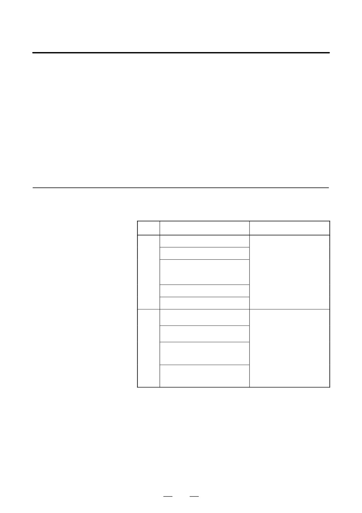
2.16.1
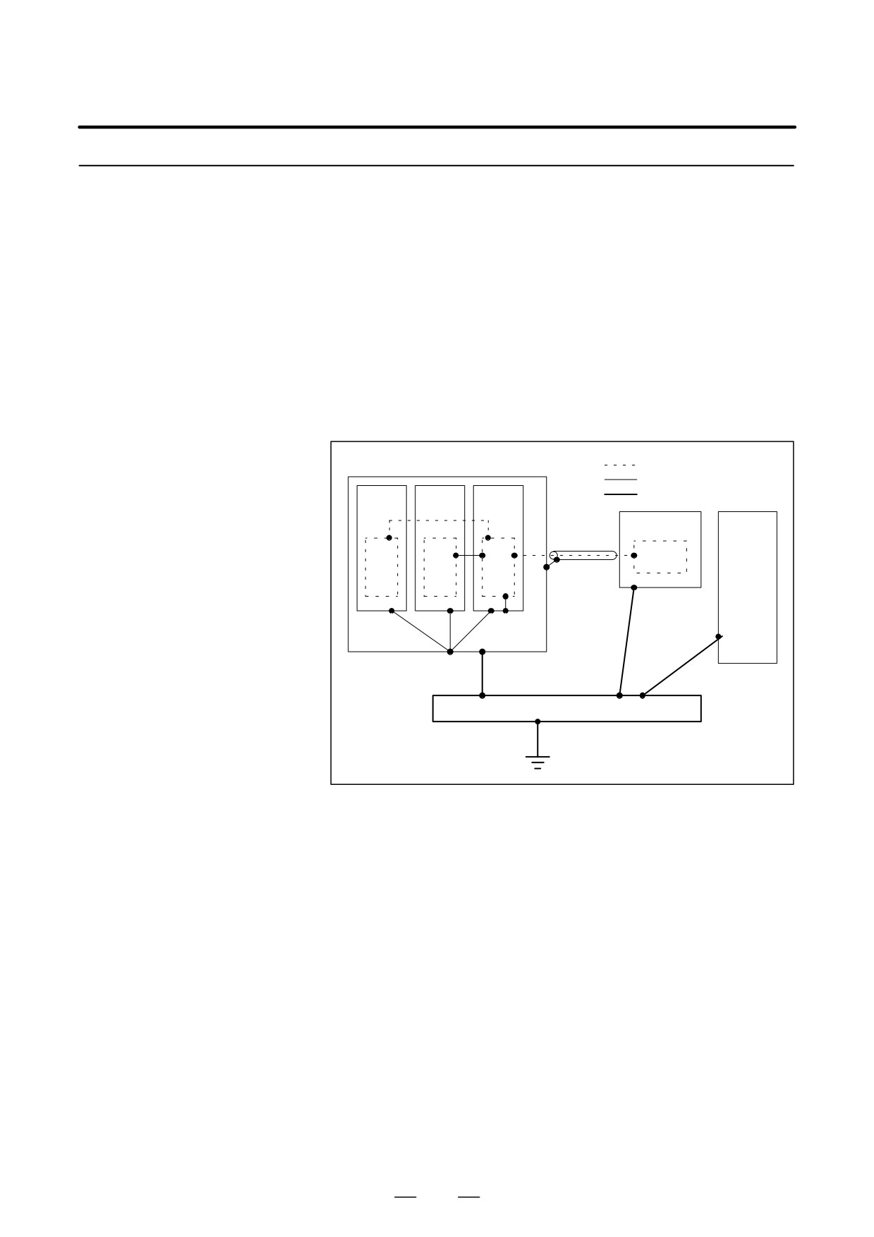
The cables used for the CNC machine tool are classified as listed in the
following table:
Separating Signal
Process the cables in each group as described in the action column.
Lines
Group
Signal line
Action
Primary AC power line
Bind the cables in group A sepa-
rately (Note 1) from groups B
Secondary AC power line
and C, or cover group A with an
electromagnetic shield (Note 2).
AC/DC power lines (containing the
See Subsec. 2.16.4 and con-
A
power lines for the servo and
nect spark killers or diodes with
spindle motors)
the solenoid and relay.
AC/DC solenoid
AC/DC relay
DC solenoid (24VDC)
Connect diodes with DC sole-
noid and relay.
Bind the cables in group B sepa-
DC relay (24VDC)
rately from group A, or cover
group B with an electromagnetic
B
DI/DO cable between the CNC
shield.
and power magnetics cabinet
Separate group B as far from
Group C as possible.
DI/DO cable between the CNC
It is more desirable to cover
and machine
group B with the shield.
240
2. HARDWARE
B-64115EN/02
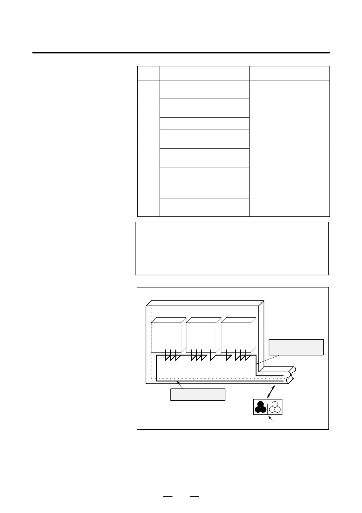
Group
Signal line
Action
Cable for position and velocity
Bind the cables in group C sepa-
feedback
rately from group A, or cover
group C with an electromagnet-
Cable between the CNC and
ic shield.
spindle amplifier
Separate group C as far from
Group B as possible.
Cable for the position coder
Be sure to perfrom shield pro-
Cable for the manual pulse gener-
cessing in Subsec. 2.16.5.
ator
C
Cable between the CNC and the
CRT/MDI
RS-232-C and RS-422 interface
cable
Cable for the battery
Other cables to be covered with the
shield
NOTE
1
The groups must be 10 cm or more apart from one another
when binding the cables in each group.
2
The electromagnetic shield refers to shielding between
groups with grounded steel plates.
Cabinet
Spindle
Servo
Control
amp.
amp.
unit
Cable of group B, C
Duct
To operator’s
panel,
motor, etc.
Cable of group A
Section
Group A
Group B, C
Cover
241
2. HARDWARE
B-64115EN/02
2.16.2
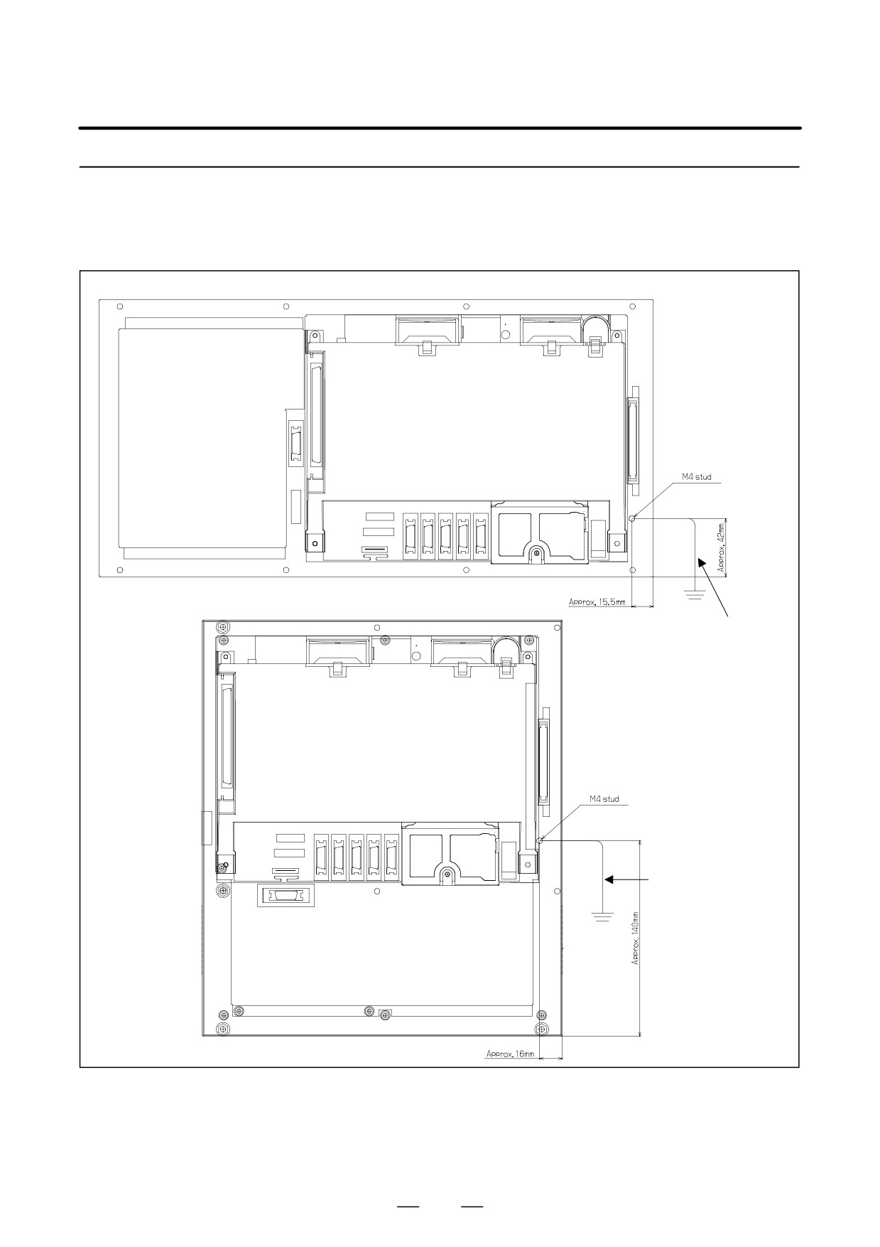
The following ground systems are provided for the CNC machine tool:
Ground
(1) Signal ground system (SG)
The signal ground (SG) supplies the reference voltage (0 V) of the
electrical signal system.
(2) Frame ground system (FG)
The frame ground system (FG) is used for safety, and suppressing
external and internal noises. In the frame ground system, the frames,
cases of the units, panels, and shields for the interface cables between
the units are connected.
(3) System ground system
The system ground system is used to connect the frame ground
systems connected between devices or units with the ground.
Signal ground system
Frame ground sysytem
Power
Servo
CNC
System ground system
magnet-
amplifier
control
ics
unit
Operator’s
unit
panel
Machine
tool
Power
magnetics
cabinet
Distribution board
Notes on connecting the
D Connect the signal ground with the frame ground (FG) at only one
ground systems
place in the CNC control unit.
D The grounding resistance of the system ground shall be 100 ohms or
less (class 3 grounding).
D The system ground cable must have enough cross-sectional area to
safely carry the accidental current flow into the system ground when
an accident such as a short circuit occurs.
(Generally, it must have the cross-sectional area of the AC power cable
or more.)
D Use the cable containing the AC power wire and the system ground
wire so that power is supplied with the ground wire connected.
242
2. HARDWARE
B-64115EN/02
2.16.3
Connecting the Ground
Terminal of the Control
Unit
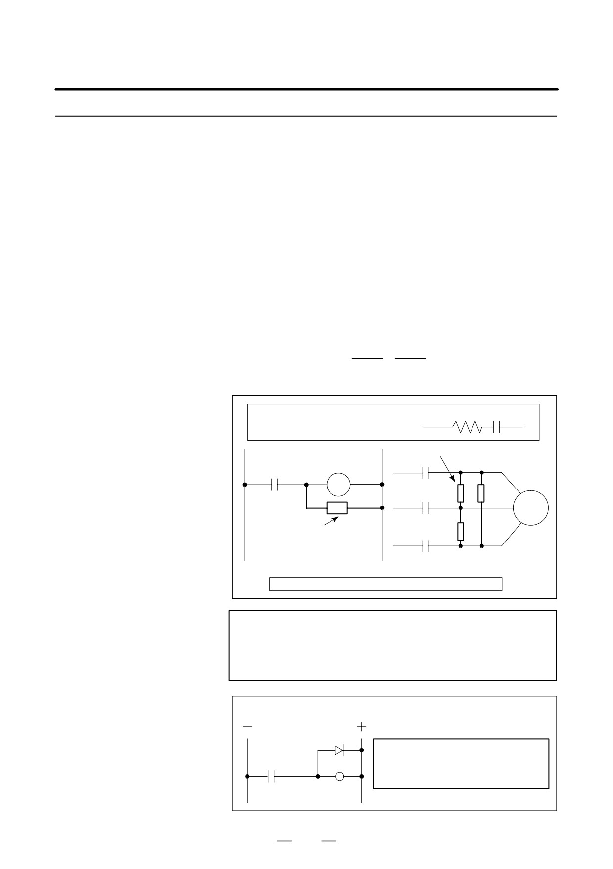
For 7.2″/8.4″LCD/MDI (horizontal) type
Rear of the unit
For 7.2″/8.4″LCD/MDI (vertical) type
Ground cable
Wire rod with a
size of 2 mm2 or more
Rear of the unit
Ground cable
Wire rod with a
size of 2 mm2 or more
Connect the 0 V line in the control unit to the ground plate of the cabinet
via the protective ground terminal (shown in the above figure).
For the positions of ground terminals for other units, see the unit outline
drawing in the appendix.
243
2. HARDWARE
B-64115EN/02
2.16.4
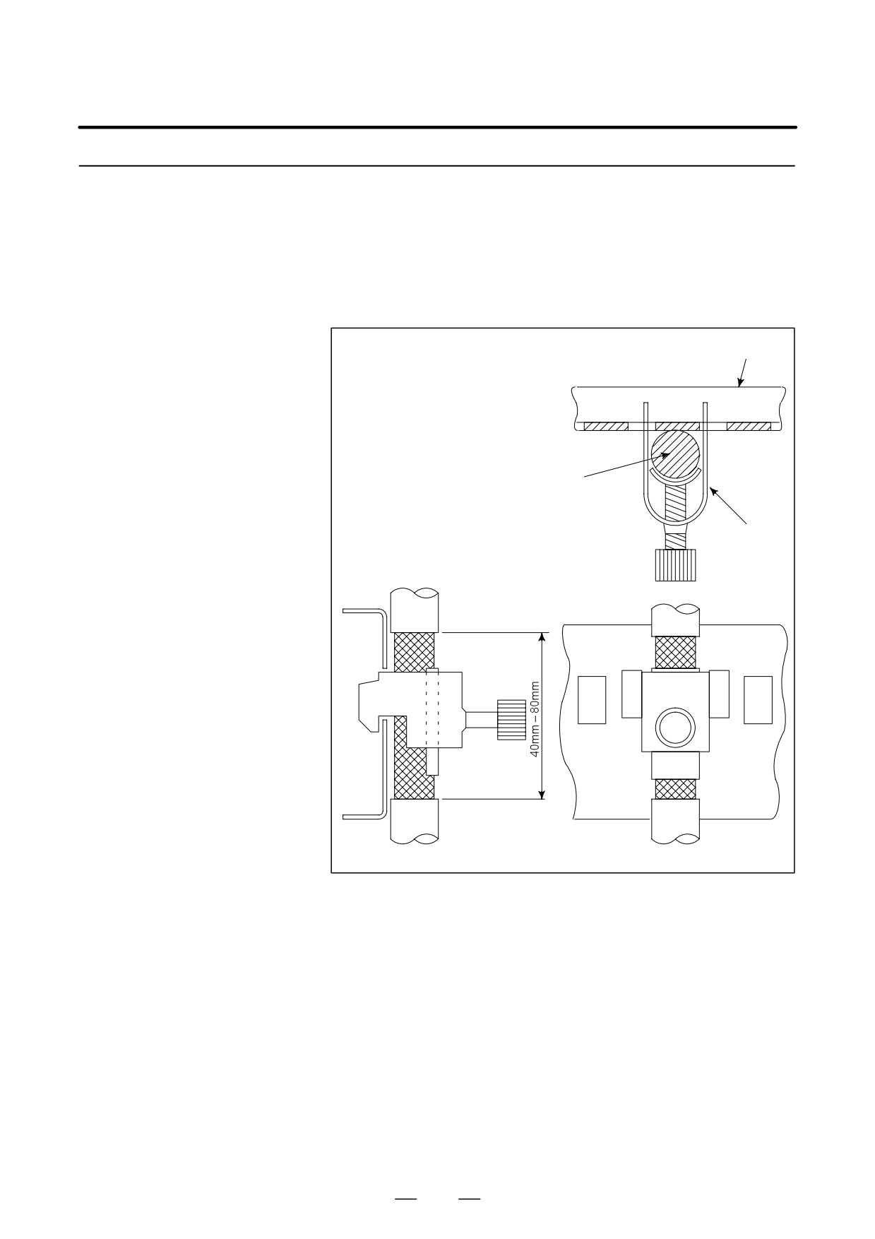
The AC/DC solenoid and relay are used in the power magnetics cabinet.
Noise Suppressor
A high pulse voltage is caused by coil inductance when these devices are
turned on or off.
This pulse voltage induced through the cable causes the electronic circuits
to be disturbed.
Notes on selecting the
D Use a spark killer consisting of a resistor and capacitor in series. This
spark killer
type of spark killer is called a CR spark killer.(Use it under AC)
(A varistor is useful in clamping the peak voltage of the pulse voltage,
but cannot suppress the sudden rise of the pulse voltage. FANUC
therefore recommends a CR spark killer.)
D The reference capacitance and resistance of the spark killer shall
conform to the following based on the current (I (A)) and DC
resistance of the stationary coil:
1) Resistance (R)
: Equivalent DC resistance of the coil
I2
I2
2) Capacitance (C) :
to
(µF)
10
20
I : Current at stationary state of the coil
R
C
Equivalent circuit of the spark killer
AC
Spark killer
relay
Motor
Spark killer
Mount the noise eliminator near a motor or a relay coil.
NOTE
Use a CR-type noise eliminator. Varistor-type noise
eliminators clamp the peak pulse voltage but cannot
suppress a sharp rising edge.
Diode (used for direct-current circuits)
Diode
Use a diode which can withstand a
voltage up to two times the applied
DC relay
voltage and a current up to two times
the applied current.
244
2. HARDWARE
B-64115EN/02
2.16.5
The CNC cables that require shielding should be clamped by the method
shown below. This cable clamp treatment is for both cable support and
Cable Clamp and
proper grounding of the shield. To insure stable CNC system operation,
Shield Processing
follow this cable clamp method.
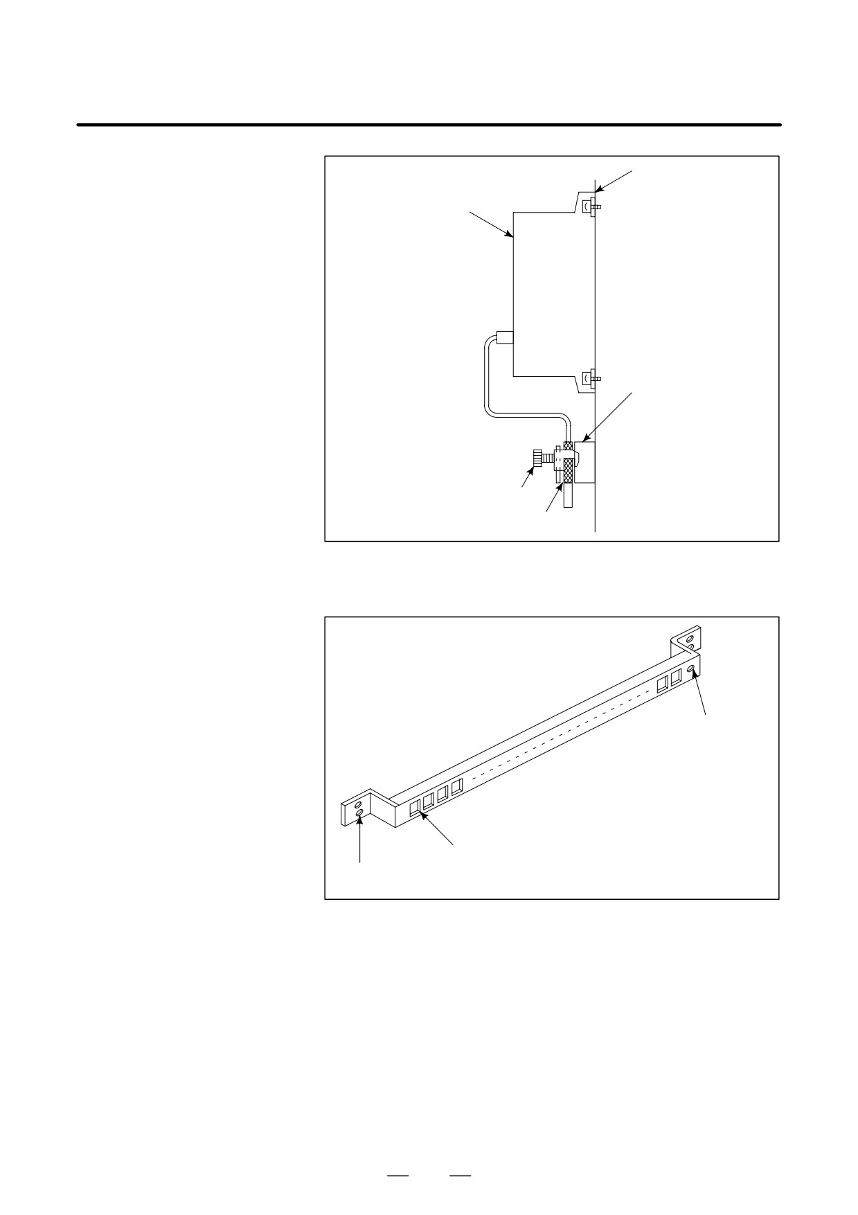
Partially peel out the sheath and expose the shield. Push and clamp by
the plate metal fittings for clamp at the part. The ground plate must be
made by the machine tool builder, and set as follows :
Ground plate
Cable
Metal fittings
for clamp
Fig. 2.16.5 (a) Cable clamp (1)
245
2. HARDWARE
B-64115EN/02
Machine side
installation
ÇÇ
board
Control unit
ÇÇ
ÇÇ
ÇÇ
ÇÇ
ÇÇ
ÇÇ
ÇÇ
ÇÇ
Ground plate
ÇÇ
ÇÇ
ÇÇ
ÇÇ
Metal fittings
ÇÇ
for clamp
ÇÇ
Shield cover
ÇÇ
Fig. 2.16.5 (b) Cable clamp (2)
Prepare ground plate like the following figure.
Ground terminal
(grounded)
Hole for securing metal fitting clamp
Mount screw hole
Fig. 2.16.5 (c) Ground plate
For the ground plate, use a metal plate of 2 mm or thicker, which surface
is plated with nickel.
246
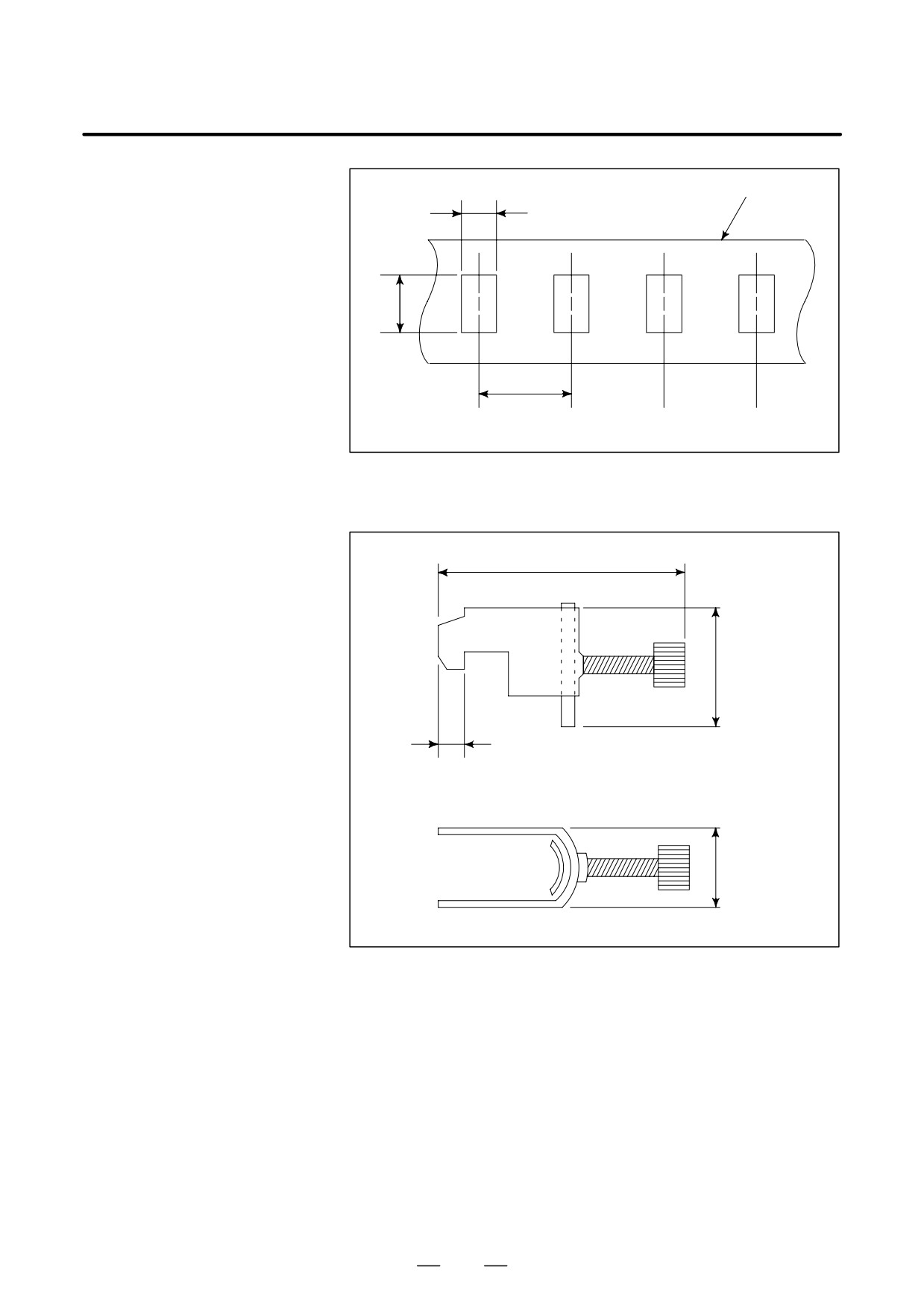
2. HARDWARE
B-64115EN/02
Ground
8mm
plate
12mm
20mm
Fig. 2.16.5 (d) Ground plate holes
(Reference) Outer drawings of metal fittings for clamp.
Max. 55mm
28mm
6mm
17mm
Fig. 2.16.5 (e) Outer drawings of metal fittings for clamp
Ordering specification for metal fittings for clamp
A02B-0124-K001 (8 pieces)
247
3. INPUT AND OUTPUT OF DATA
B-64115EN/02
INPUT AND OUTPUT OF DATA
3
After you change a SRAM module, you must set various data again.
This chapter describes the procedures to input and output the parameters,
the part programs and the tool offset values.
3.1
SETTING PARAMETERS FOR
INPUT/OUTPUT
249
3.2
INPUTTING/OUTPUTTING DATA
251
3.3
DATA INPUT/OUTPUT ON THE
ALL IO SCREEN
260
3.4
DATA INPUT/OUTPUT USING A
MEMORY CARD
275
248
3. INPUT AND OUTPUT OF DATA
B-64115EN/02
3.1
SETTING
PARAMETERS
FOR INPUT/OUTPUT
D Setting procedure of
Parameter writing is enabled with following steps 1 to 3.
parameters
1.
Set to MDI mode or emergency stop state.
OFFSET
2.
Press
SETTING
key several times or press soft key [SETING] to display
SETTING (HANDY) screen.
3.
Set the cursor to PARAMETER WRITE and, press
1
and
INPUT
keys in this order. Here alarm 100 will be displayed.
4.
Press
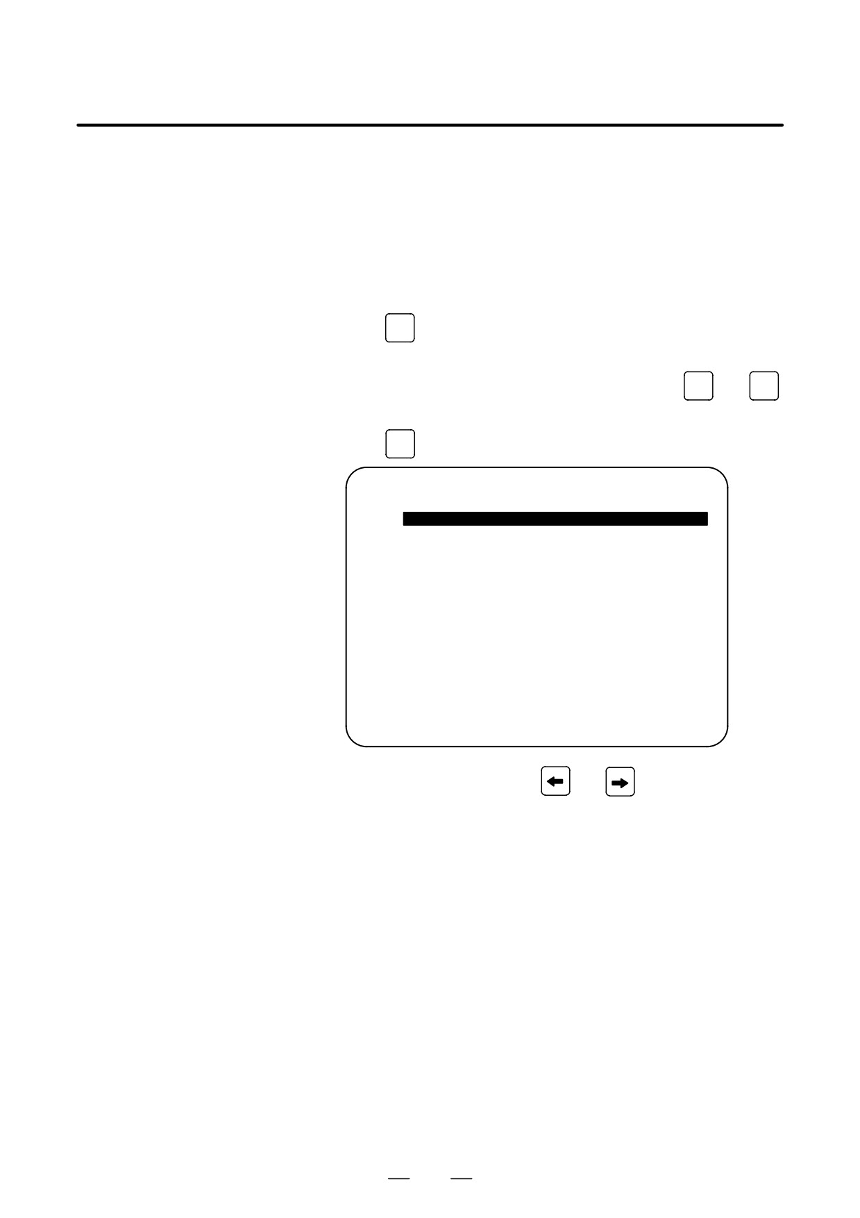
SYSTEM
key several times to display the following screen.
PARAMETER (SETTING)
O1234N12345
0000
SEQ
INI ISO TVC
0
0
0
0
0
0
0
0
0001
FCV
0
0
0
0
0
0
0
0
0012
RMV
MIR
X
0
0
0
0
0
0
0
0
Y
0
0
0
0
0
0
0
0
Z
0
0
0
0
0
0
0
0
B
0
0
0
0
0
0
0
0
0020 I/O CHANNEL
S
0 T0000
REF **** *** ***
10:15:30
[ F SRH ][ READ
][ PUNCH ][DELETE ][
]
To make the cursor display in bit unit,
press the cursor key
or
5.
Press soft key[(OPRT)] and the following operation menu
is
displayed.
1) Soft key [NO. SRH] : Searched by number.
Examination) Parameter number → [NO. SRH].
2) Soft key [ON : 1] : Item with cursor position is set to 1
(bit parameter)
3) Soft key [OFF : 0] : Item with cursor position is set to 0
(bit parameter)
4) Soft key [+INPUT] : Input value is added to the value at cursor
(word type)
5) Soft key [INPUT] : Input value is replaced with the value at
cursor (word type)
6) Soft key [READ] : Parameters are input from reader/puncher
interface.
7) Soft key [PUNCH] : Parameters are output to reader/puncher
interface.
249