FANUC Series 30i-MODEL B, 31i-MODEL B, 32i-MODEL B. MAINTENANCE MANUAL - page 18
8.DIGITAL SERVO
B-64485EN/01
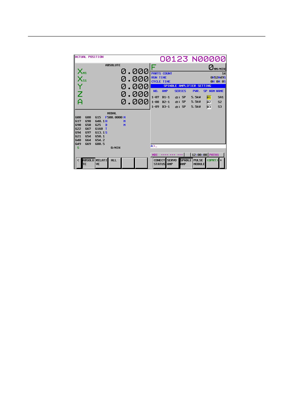
(3) Spindle amplifier setting screen
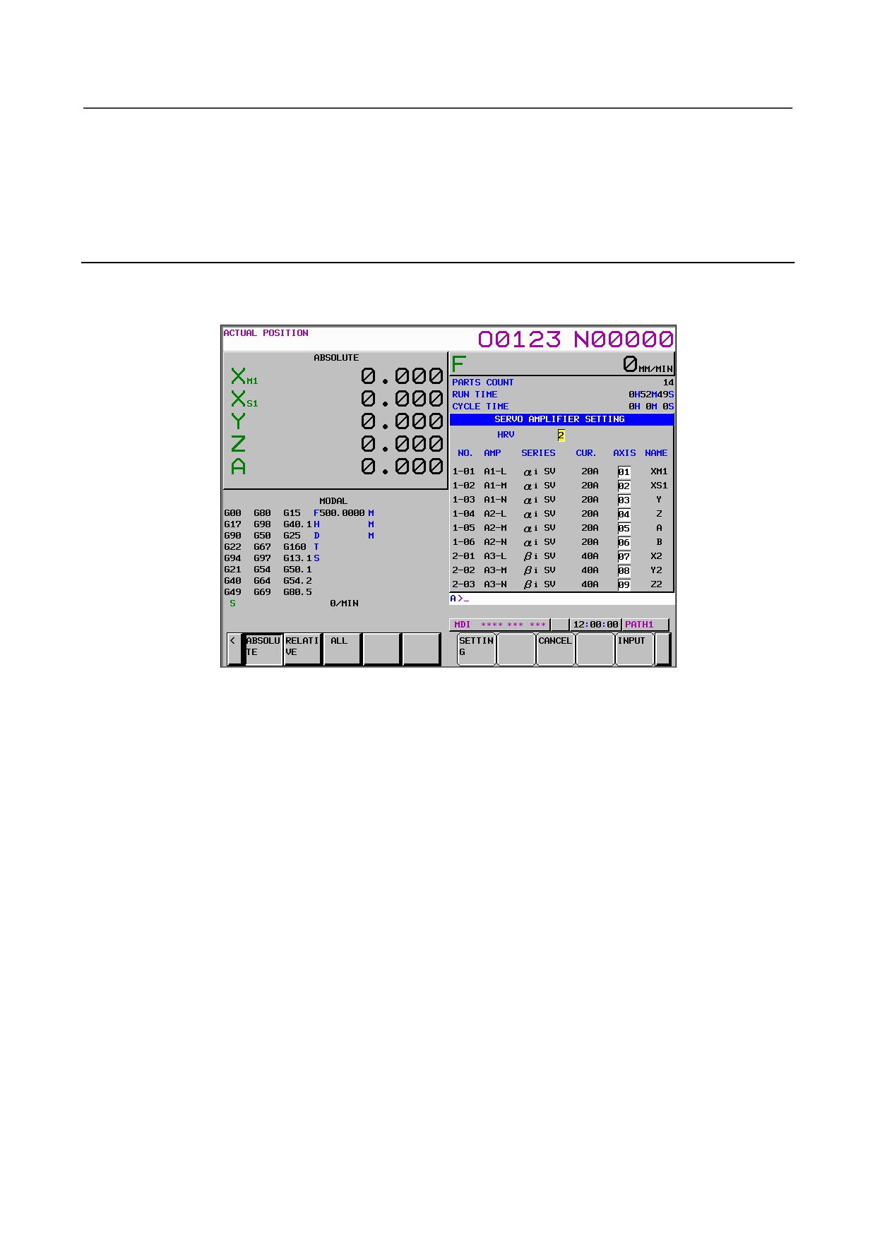
The spindle amplifier setting screen displays spindle amplifier information.
The spindle amplifier setting screen consists of the following items:
•
NO
Slave number
An FSSB line number (1: First FSSB line, 2: Second FSSB line, 3: Third FSSB line), a hyphen
(-), and a slave number (connection number for the line) are displayed. (The maximum number
of slaves per line is 32.)
•
AMP
Amplifier type
This consists of the letter B, which stands for “spindle amplifier”, a number indicating the
placing of the spindle amplifier, as counted from that nearest to the CNC, and an alphabetic
character indicating the axis order in the spindle amplifier (1: First spindle for a spindle
amplifier).
•
The following items are displayed as spindle amplifier information:
-
SERIES
Spindle amplifier type and series
-
PWR
Maximum output
•
SP NUM
Spindle number
The spindle number assigned to the spindle amplifier is displayed. “0” is displayed if an
FSSB-related alarm is issued or no spindle number is assigned.
•
NAME
Spindle name
The spindle name corresponding to the spindle number is displayed. When the spindle number
is 0, nothing is displayed.
- 492 -
B-64485EN/01
8.DIGITAL SERVO
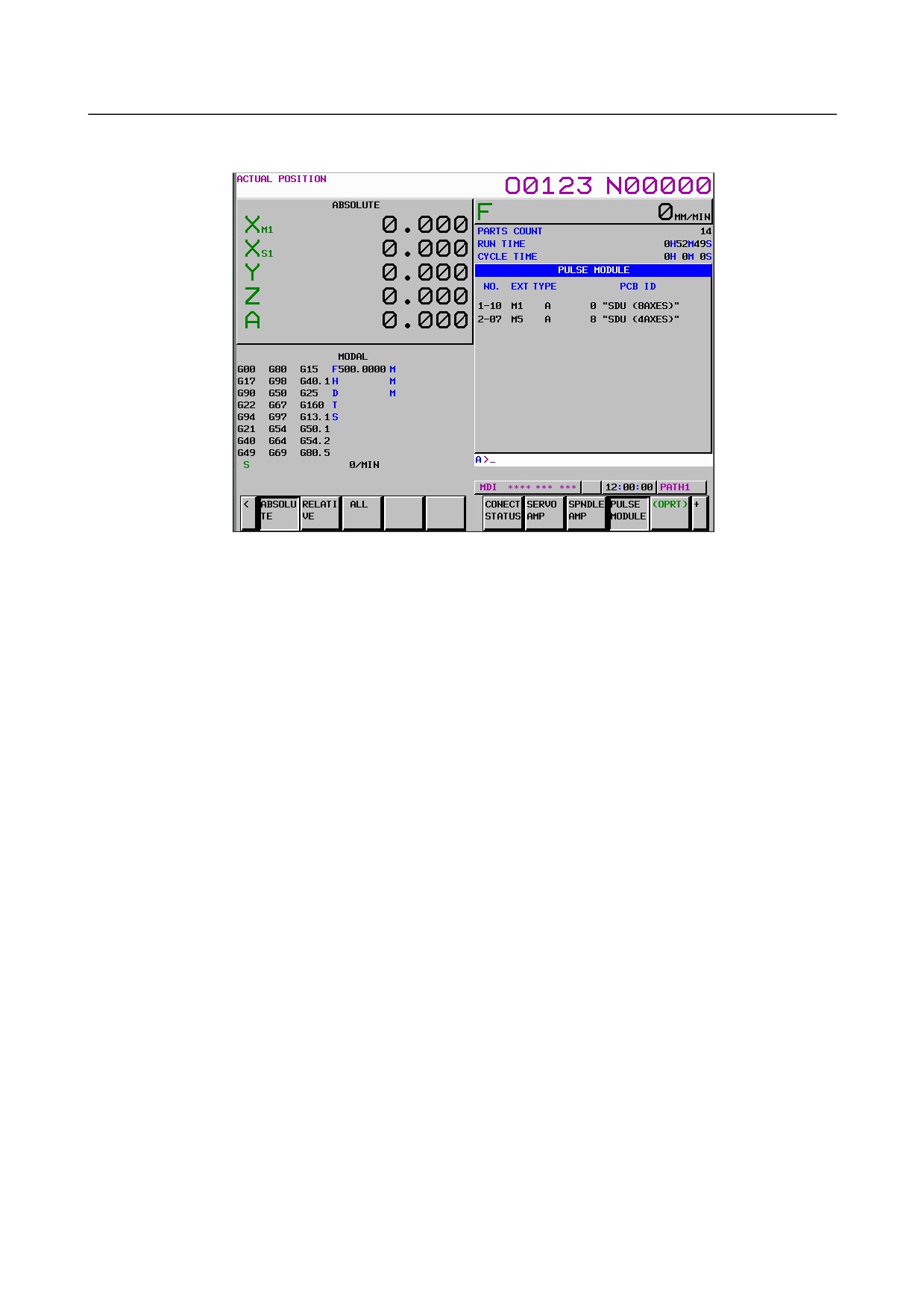
(4) Separate detector interface unit screen
The separate detector interface unit screen displays information on separate detector interface units.
The separate detector interface unit screen displays the following items:
•
NO
Slave number
An FSSB line number (1: First FSSB line, 2: Second FSSB line, 3: Third FSSB line), a hyphen
(-), and a slave number (connection number for the line) are displayed. (While the maximum
number of slaves per line is 32, the maximum number of separate detector interface units per
line is 4.)
•
The following items are displayed as separate detector interface unit information:
-
EXT
This consists of the letter M, which stands for "separate detector interface unit", and a
number indicating the placing of the separate detector interface unit, as counted from that
nearest to the CNC. For the second FSSB line, M5 is displayed for the first separate
detector interface unit since the number starts from 5. For the third FSSB line, M9 is
displayed for the first separate detector interface unit since the number starts from 9.
-
TYPE
This is a letter indicating the type of the separate detector interface unit.
-
PCB ID
The ID of the separate detector interface unit is displayed.
The separate detector interface unit ID is followed by SDU (8AXES) when 8-axes
separate detector interface unit or SDU (4AXES) when 4-axes separate detector interface
unit.
- 493 -
8.DIGITAL SERVO
B-64485EN/01
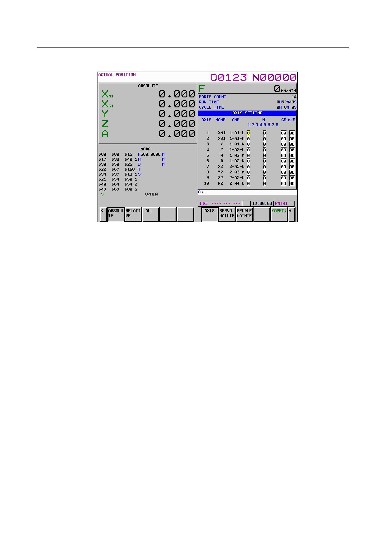
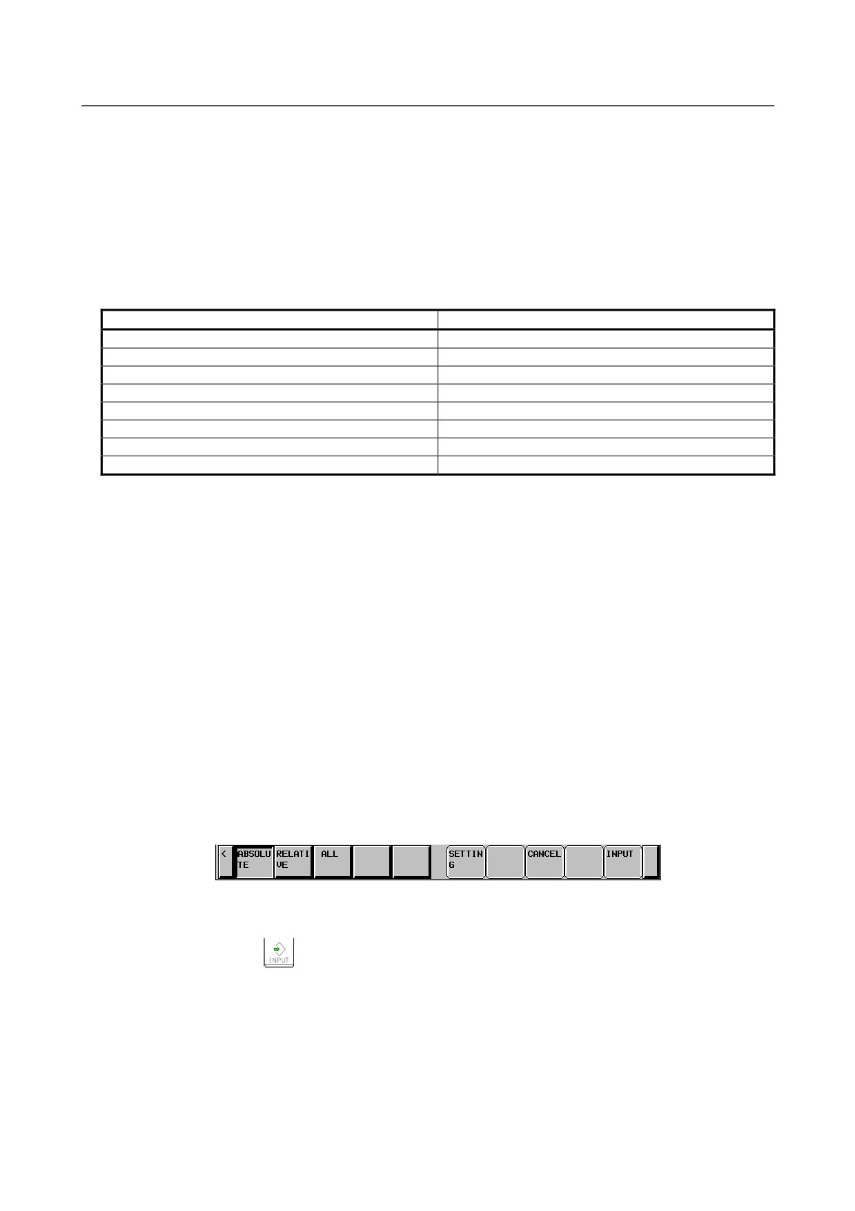
(5) Axis setting screen
The axis setting screen displays the information of axis.
The axis setting screen displays the following items. Any item that cannot be set is not displayed.
(When the first and fifth separate detector interface units are connected and Cs contour control and
tandem control can be used, the screen shown in above figure is displayed.)
•
AXIS
Controlled axis number
This item is the placing of the NC controlled axis.
•
NAME
Program axis name for each axis
•
AMP
FSSB line number and amplifier type of the servo amplifier connected to each
axis
•
M1
Connector number of the first or ninth (first unit for the third FSSB line) separate
detector interface unit
•
M2
Connector number of the second or tenth separate detector interface unit
•
M3
Connector number of the third or eleventh separate detector interface unit
•
M4
Connector number of the fourth or twelfth separate detector interface unit
•
M5
Connector number of the fifth (first unit for the second FSSB line) separate
detector interface unit
•
M6
Connector number of the sixth separate detector interface unit
•
M7
Connector number of the seventh separate detector interface unit
•
M8
Connector number of the eighth separate detector interface unit
Connector numbers set by FSSB automatic setting are displayed.
•
Cs
Cs contour controlled axis
The spindle number for the Cs contour controlled axis set by FSSB automatic setting is
displayed.
•
M/S
Master axis / Slave axis (Slave axis / Dummy axis)
Either of the following settings is displayed: Master axis/slave axis setting for tandem control
or slave axis/dummy axis setting for the electronic gear box (EGB) set by FSSB automatic
setting.
The M1 to M8, Cs, and M/S values are to be set by FSSB automatic setting and do not indicate
current effective settings. The previous values set normally are displayed first after power-on. “0” is
displayed when an FSSB-related alarm is issued.
- 494 -
B-64485EN/01
8.DIGITAL SERVO
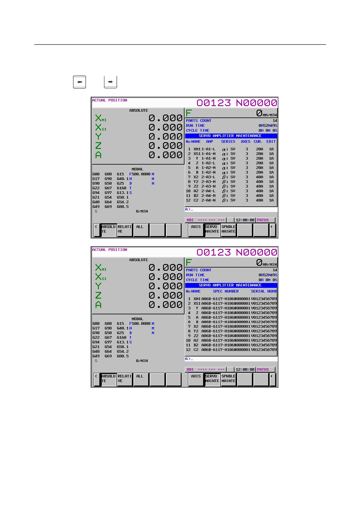
(6) Servo amplifier maintenance screen
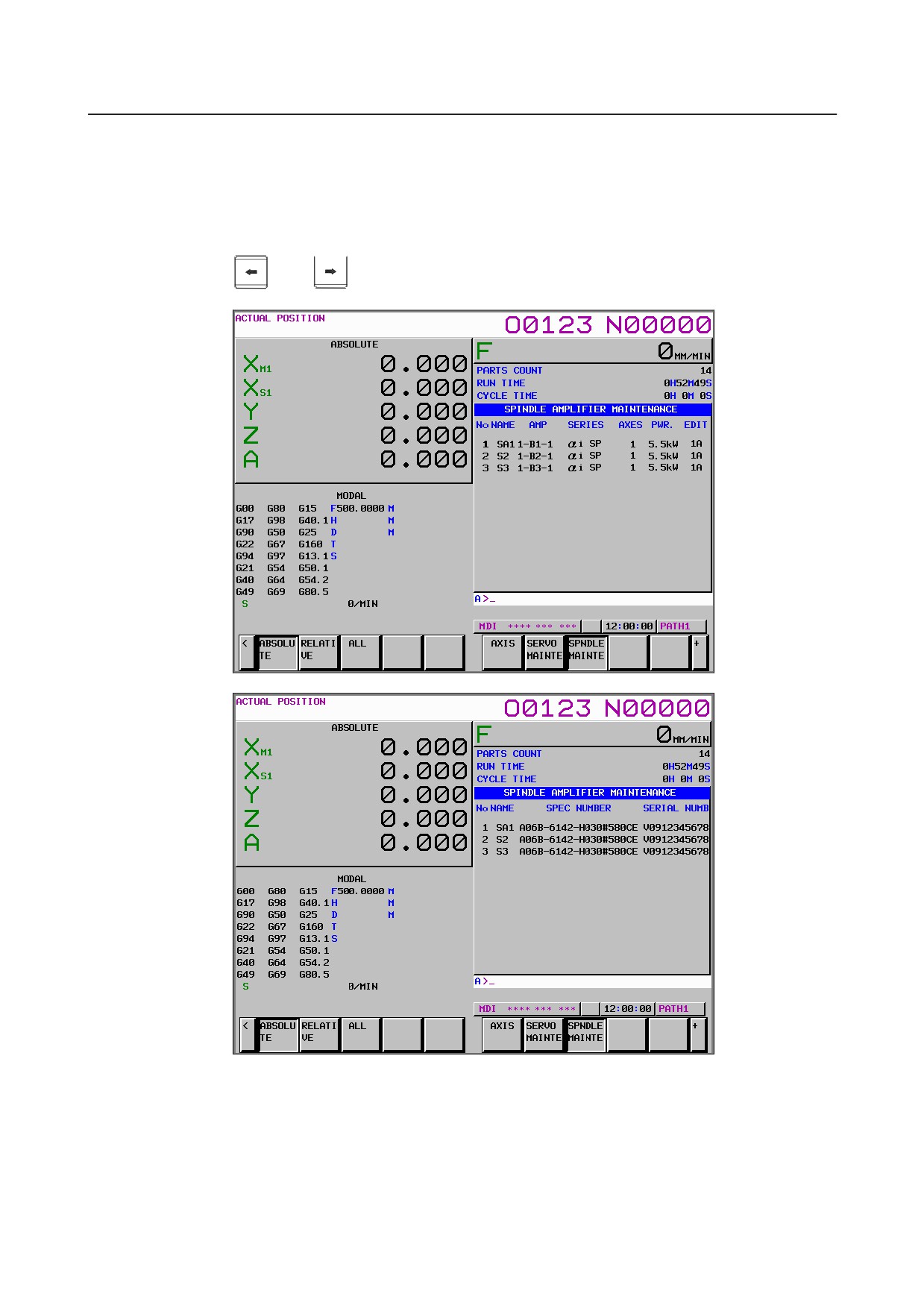
The servo amplifier maintenance screen displays maintenance information for servo amplifiers. This
screen consists of the following two pages, either of which can be selected by pressing the cursor
keys
and
The servo amplifier maintenance screen displays the following items:
•
No
Controlled axis number
•
NAME
Program axis name for each axis
•
AMP
FSSB line number and amplifier type of the servo amplifier connected to
each axis
•
SERIES
Type and series of the servo amplifier connected to each axis
•
AXES
Maximum number of axes controlled by a servo amplifier connected to each
axis
•
CUR
Maximum rating current for servo amplifiers connected to each axis
•
EDIT
Version number of a servo amplifier connected to each axis
- 495 -
8.DIGITAL SERVO
B-64485EN/01
•
SPEC NUMBER. Amplifier drawing number of the servo amplifier connected to each axis
•
SERIAL NUMB.. Serial number of the servo amplifier connected to each axis
(7) Spindle amplifier maintenance screen
The spindle amplifier maintenance screen displays maintenance information for spindle amplifiers.
This screen consists of the following two pages, either of which can be selected by pressing the
cursor keys
and
The spindle amplifier maintenance screen displays the following items:
•
No
Spindle number
•
NAME
Spindle name
•
AMP
FSSB line number and amplifier type of the spindle amplifier connected to
each axis
•
SERIES
Type and series of the spindle amplifier connected to each axis
- 496 -
B-64485EN/01
8.DIGITAL SERVO
•
AXES
Maximum number of axes controlled by a spindle amplifier connected to
each axis
•
PWR
Rated output of the spindle amplifier connected to each axis
•
EDIT
Version number of a servo amplifier connected to each axis
•
SPEC NUMBER. Amplifier drawing number of the spindle amplifier connected to each axis
•
SERIAL NUMB.. Serial number of the spindle amplifier connected to each axis
FSSB automatic setting procedure
To perform FSSB automatic setting, set items on the FSSB setting screens in (1) to (3) below.
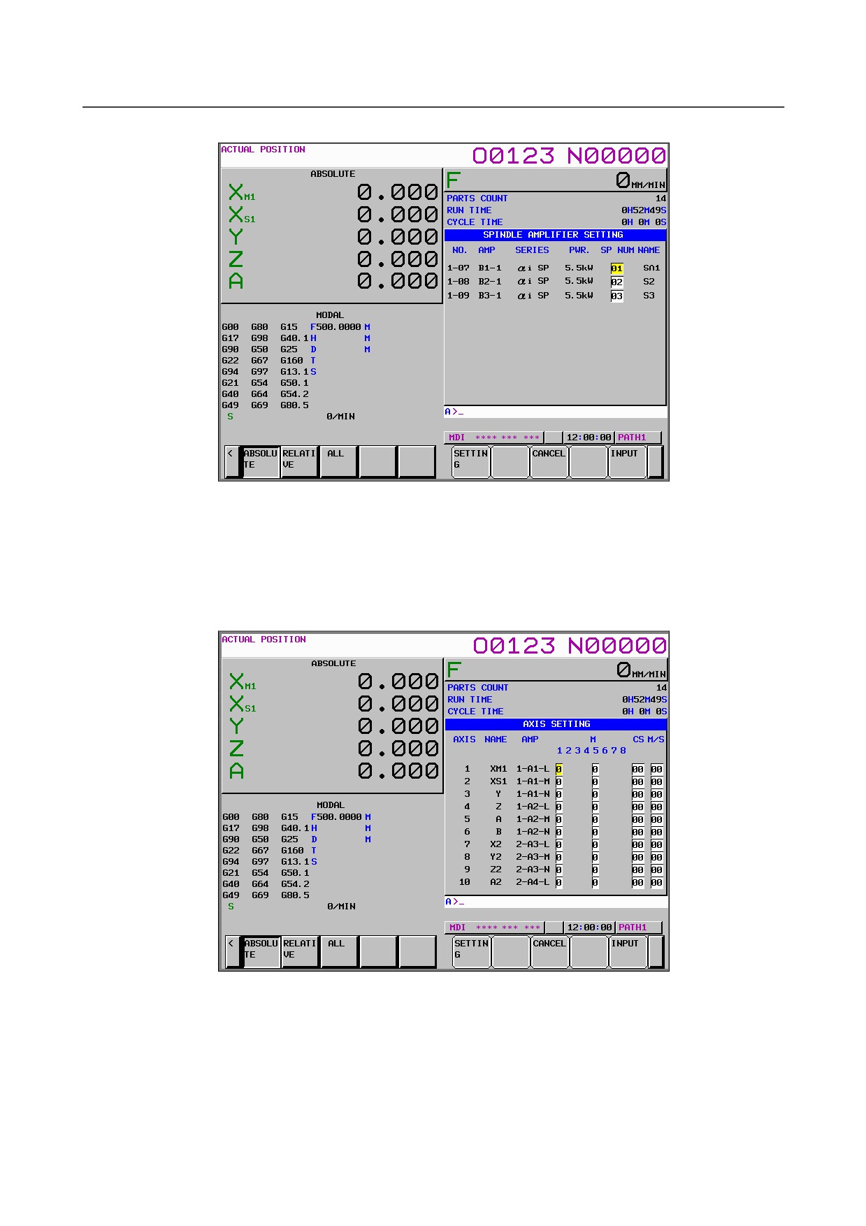
(1) Servo amplifier setting screen
The servo amplifier setting screen displays the following items:
•
HRV
Current loop
For this item, enter a value between 2 to 4.
If a number that falls outside this range is entered, the warning message, “DATA IS OUT OF
RANGE” appears.
•
AXIS
Controlled axis number
For this item, enter a value of between 0 and the maximum number of controlled axes.
If a number that falls outside this range is entered, the warning message, “DATA IS OUT OF
RANGE” appears. Setting 0 means that the relevant servo amplifier is not used.
- 497 -
8.DIGITAL SERVO
B-64485EN/01
(2) Spindle amplifier setting screen
The spindle amplifier setting screen displays the following items:
•
SP NUM
Spindle number
For this item, enter a value of between 0 and the maximum number of spindles.
If a number that falls outside this range is entered, the warning message, “DATA IS OUT OF
RANGE” appears. Setting 0 means that the relevant spindle amplifier is not used.
(3) Axis setting screen
On the axis setting screen, the following items can be specified:
•
M1
Connector number of the first or ninth (first unit for the third FSSB line) separate
detector interface unit
•
M2
Connector number of the second or tenth separate detector interface unit
•
M3
Connector number of the third or eleventh separate detector interface unit
•
M4
Connector number of the fourth or twelfth separate detector interface unit
•
M5
Connector number of the fifth (first unit for the second FSSB line) separate
detector interface unit
- 498 -
B-64485EN/01
8.DIGITAL SERVO
•
M6
Connector number of the sixth separate detector interface unit
•
M7
Connector number of the seventh separate detector interface unit
•
M8
Connector number of the eighth separate detector interface unit
For an axis that uses each separate detector interface unit, enter a connector number using a
number 1 to 8 (maximum number of connectors on a separate detector interface unit).
When a separate detector interface unit is not used, enter 0. If a number that falls outside this
range is entered, the warning message, “DATA IS OUT OF RANGE” appears. For a separate
detector interface unit which is not connected, items are not displayed and values cannot be
entered.
Connector
Connector number
JF101
1
JF102
2
JF103
3
JF104
4
JF105
5
JF106
6
JF107
7
JF108
8
•
CS
Cs contour controlled axis
Enter a spindle number between 1 and the maximum number of spindles for the Cs contour
controlled axis. When a Cs contour controlled axis is not used, enter 0. If a number that falls
outside this range is entered, the warning message, “DATA IS OUT OF RANGE” appears.
When Cs contour control cannot be used, this item is not displayed and any value cannot be
entered.
•
M/S
Master axis / Slave axis (Slave axis / Dummy axis)
Enter an odd number for the master axis and an even number for the slave axis for tandem
control. These numbers must be consecutive and within a range between 1 and the maximum
number of controlled axes. Enter an odd number for the slave axis and an even number for the
dummy axis for the electronic gear box (EGB). These numbers must be consecutive and within
a range between 1 and the maximum number of controlled axes. If a number that falls outside
this range is entered, the warning message, “DATA IS OUT OF RANGE” appears. For the
slave and dummy axes for EGB, set bit 0 (SYN) of parameter No. 2011 to 1. When both
tandem control and electronic gear box cannot be used, this item is not displayed and any value
cannot be entered.
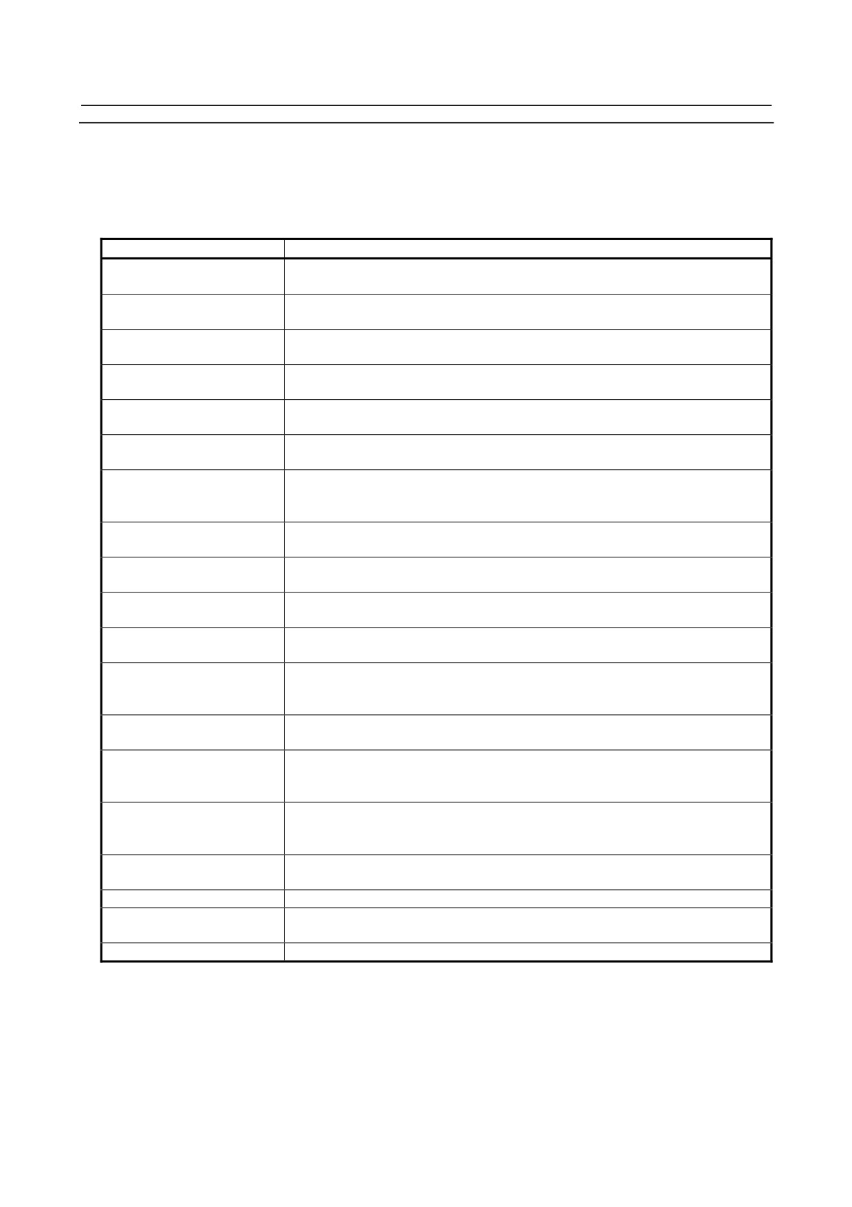
On an FSSB setting screen (other than the connection status screen, servo amplifier maintenance screen,
or spindle amplifier maintenance screen), pressing the soft key [(OPRT)] displays the following soft keys:
To enter data, place the machine in the MDI mode or the emergency stop state, position the cursor to a
desired input item position, then enter desired data and press the soft key [INPUT].
(Alternatively, press the
key on the MDI unit.)
When the soft key [SETTING] is pressed after data has been entered, a warning message listed below is
displayed if the entered data contains an error. When the data is valid, the corresponding FSSB-related
parameters are set up. To restore the previous value normally set if, for example, an entered value is
incorrect, press the soft key [CANCEL].
When this screen is first displayed after power-on, the previous values set normally are displayed.
- 499 -
8.DIGITAL SERVO
B-64485EN/01
FSSB automatic setting warning messages
If an invalid setting is detected at FSSB automatic setting, a warning message listed below is displayed.
EGB dummy axis setting means setting an even number for M/S on the axis setting screen for an axis for
which bit 0 (SYN) of parameter No. 2011 is set to 1. EGB slave axis setting means setting an odd number
for M/S on the axis setting screen for an axis for which bit 0 (SYN) of parameter No. 2011 is set to 1.
Warning message
Cause
Cs and M/S are set with the
On the axis setting screen, a value is specified for Cs and M/S for an axis. Do not
same axis
specify any value for Cs and M/S simultaneously.
Cs and M1-8 are set with the
On the axis setting screen, a value is specified for Cs and M1-8 for an axis. Do
same axis
not specify any value for Cs and M1-8 simultaneously.
Same number is set in AXIS
On the servo amplifier setting screen, an axis number is set more than once.
Specify each axis number only once.
Same number is set in SP
On the spindle amplifier setting screen, a spindle number is set more than once.
NUM
Specify each spindle number only once.
Same number is set in CS
On the axis setting screen, a value is set for Cs more than once. Specify each
value for Cs only once.
Same number is set in M/S
On the axis setting screen, a value is set for M/S more than once. Specify each
value for M/S only once.
AXIS and Cs are set with the
An axis number for which a value is set for Cs on the axis setting screen is set for
same axis
AXIS on the servo amplifier setting screen. Do not set any axis number for which a
value is set for Cs, on the servo amplifier setting screen.
Too many slaves (HRV4)
The maximum number (7) of slaves per FSSB line for servo HRV4 control is
exceeded. Reduce the number of slaves connected to an FSSB line to 7 or less.
Too many slaves (HRV3)
The maximum number (15) of slaves per FSSB line for servo HRV3 control is
exceeded. Reduce the number of slaves connected to an FSSB line to 15 or less.
Too many slaves (HRV2)
The maximum number (32) of slaves per FSSB line for servo HRV2 control is
exceeded. Reduce the number of slaves connected to an FSSB line to 32 or less.
M/S is set with HRV4
For servo HRV4 control, a value is set for M/S. Do not set any value for M/S for
servo HRV4 control.
AXIS is set with EGB dummy
An axis number set for EGB dummy axis setting is set for AXIS on the servo
axis
amplifier setting screen. Do not set any axis number for EGB dummy axis setting,
on the servo amplifier screen.
M/S setting is illegal(EGB)
For M/S, the EGB slave axis setting corresponding to an EGB dummy axis setting
is not made. Make the EGB slave axis setting.
AXIS is not set with EGB
An axis number for EGB slave axis setting is not set for AXIS on the servo
slave axis
amplifier setting screen. Set the axis number for EGB slave axis setting, on the
servo amplifier setting screen.
AXIS is not set with M/S axis
An axis number set for M/S on the axis setting screen is not set for AXIS on the
servo amplifier setting screen. Set the axis number for M/S, on the servo amplifier
setting screen.
EGB dummy axis setting is
EGB dummy axis setting is made when 32 slaves are connected to the second
illegal
FSSB line. Decrease the number of slaves connected to the second FSSB line.
M/S setting is illegal
Invalid M/S setting. Correct the M/S setting.
Setting is illegal(servo)
Invalid servo axis setting (servo amplifier setting, axis setting). Correct the servo
axis setting.
Setting is illegal(spindle)
Invalid spindle setting. Correct the spindle setting.
- 500 -
B-64485EN/01
8.DIGITAL SERVO
8.3
SERVO TUNING SCREEN
8.3.1
Parameter Setting
Set a parameter to display the servo tuning screen.
#7
#6
#5
#4
#3
#2
#1
#0
3111
SVS
[Input type] Setting input
[Data type] Bit path
#0 SVS 0 : Servo tuning screen is not displayed.
1 : Servo tuning screen is displayed.
8.3.2
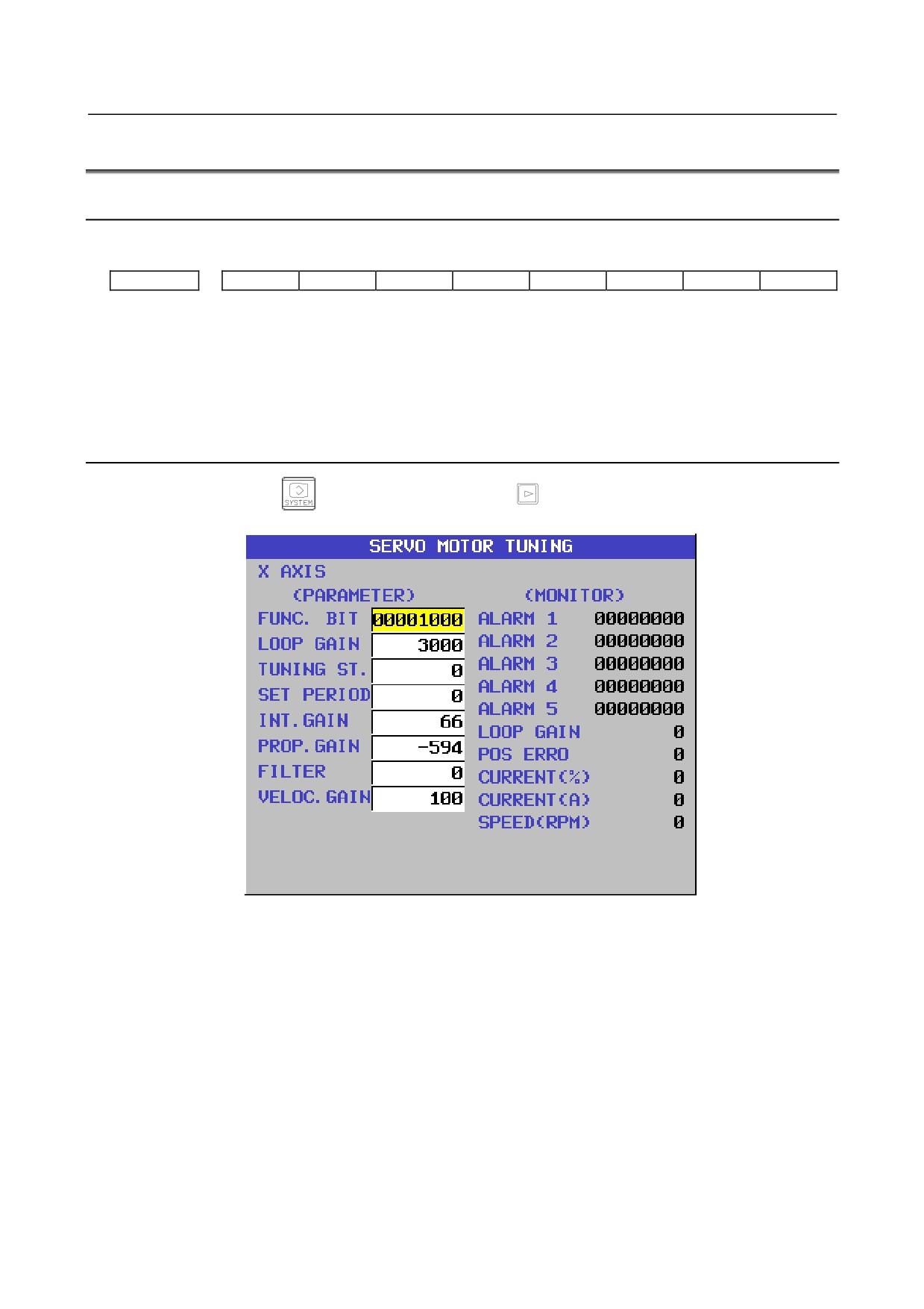
Displaying Servo Tuning Screen
1
Press function key
key, continuous menu key
, and soft key [SV. PARA] in this order.
2
Press soft key [SV.TUN] to select the servo tuning screen.
(1)
(9)
(10)
(2)
(11)
(3)
(12)
(4)
(13)
(5)
(14)
(6)
(15)
(7)
(16)
(8)
(17)
(18)
(1) Function bit
: Parameter No.2003
(2) Loop gain
: Parameter No.1825
(3) Tuning start
:
(4) Set period
:
(5) Integral gain
: Parameter No.2043
(6) Proportional gain
: Parameter No.2044
(7) Filter
: Parameter No.2067
(Parameter No.2021)+256
(8) Velocity gain
: Set value
×100
256
(9) Alarm 1
: Diagnosis No.200
(10) Alarm 2
: Diagnosis No.201
(11) Alarm 3
: Diagnosis No.202
(12) Alarm 4
: Diagnosis No.203
(13) Alarm 5
: Diagnosis No.204
(14) Loop gain
: Actual loop gain
- 501 -
8.DIGITAL SERVO
B-64485EN/01
(15) Position error
: Actual position error (Diagnosis No.300)
(16) Current(%)
: Indicate current with % to the rated value.
(when the bit 5 (SPF) of parameter No. 2014 is set to 0)
Actual output(%) : Indicate output value with % to the motor rated value.
(when the bit 5 (SPF) of parameter No. 2014 is set to 1)
(17) Current(A)
: Indicate current with A (peak value).
(not indicated if bit 5 (SPF) of parameter No.2014 is set to 1)
(18) Speed RPM
: Number of motor actual rotation
#7
#6
#5
#4
#3
#2
#1
#0
Alarm 1
OVL
LVA
OVC
HCA
HVA
DCA
FBA
OFA
Alarm 2
ALD
EXP
Alarm 3
CSA
BLA
PHA
RCA
BZA
CKA
SPH
Alarm 4
DTE
CRC
STB
PRM
Alarm 5
OFS
MCC
LDM
PMS
FAN
DAL
ABF
NOTE
The empty fields do not represent alarm codes.
8.4
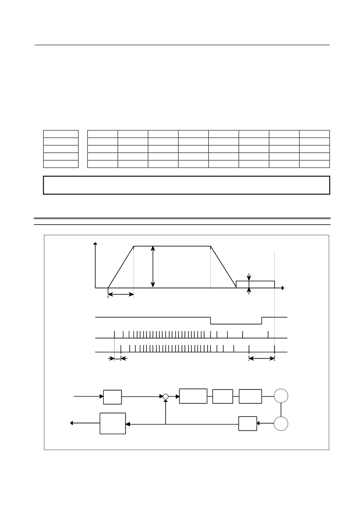
ADJUSTING REFERENCE POSITION (DOG METHOD)
Overview
Speed
Rapid traverse
FL rate
(Parameter No. 1420α)
(Parameter No. 1425α)
Time
Rapid traverse acc./dec. time constant (Parameter No. 1620α)
*DECα
PCZ
Grid
Grid shift amount
Reference counter capacity
(Parameter No. 1850)
(Parameter No. 1821)
10mm/rev
10000P
Error
Proportion
Speed
M
CMR
counter
gain
loop
Command
+
-
×4
(Serial)
Reference
F⋅FG
PC
counter
GRID
Counter capacity
10000P/rev (Flexible feed gear)
10000P
- 502 -
B-64485EN/01
8.DIGITAL SERVO
Parameter
There are the following related parameters.
#7
#6
#5
#4
#3
#2
#1
#0
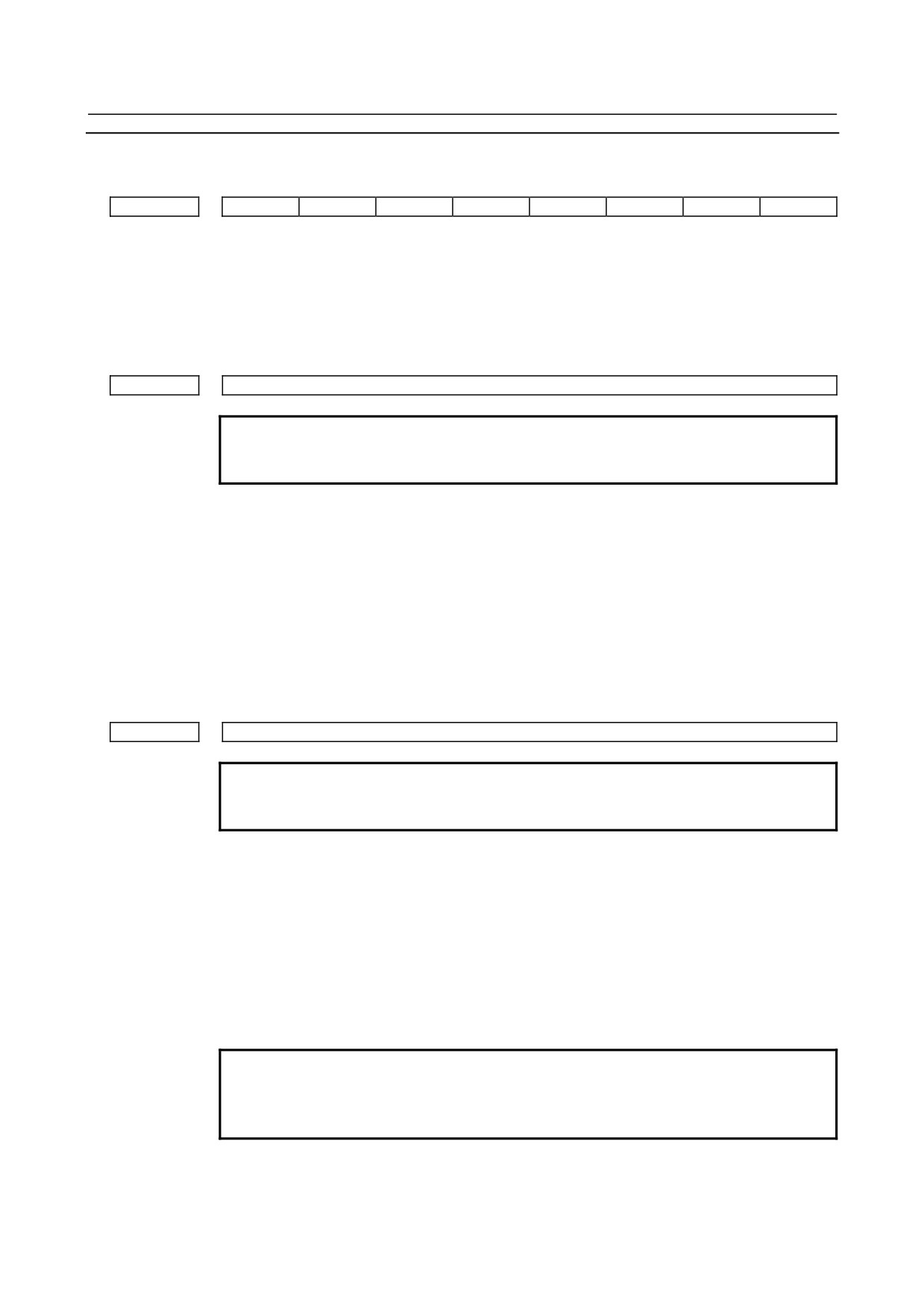
1005
DLZx
[Input type] Parameter input
[Data type] Bit axis
#1 DLZx Function for setting the reference position without dogs
0: Disabled
1: Enabled
1821
Reference counter size for each axis
NOTE
When this parameter is set, the power must be turned off before
operation is continued.
[Input type] Parameter input
[Data type] 2-word axis
[Unit of data] Detection unit
[Valid data range] 0 to 999999999
Set a reference counter size.
As a reference counter size, specify a grid interval for reference position return based on
the grid method.
When a value less than 0 is set, the specification of 10000 is assumed.
When a linear scale with absolute address reference marks is used, set the interval of
mark 1.
1850
Grid shift and reference position shift for each axis
NOTE
When this parameter is set, the power must be turned off before
operation is continued.
[Input type] Parameter input
[Data type] 2-word axis
[Unit of data] Detection unit
[Valid data range] -99999999 to 99999999
To shift the reference position, the grid can be shifted by the amount set in this parameter.
Up to the maximum value counted by the reference counter can be specified as the grid
shift.
In case of bit 4 (SFDx) of parameter No. 1008 is 0: Grid shift
In case of bit 4 (SFDx) of parameter No. 1008 is 1: Reference point shift
NOTE
For setting the reference position without dogs, only the grid shift
function can be used. (The reference position shift function cannot
be used.)
- 503 -
8.DIGITAL SERVO
B-64485EN/01
#7
#6
#5
#4
#3
#2
#1
#0
1815
APCx
APZx
OPTx
[Input type] Parameter input
[Data type] Bit axis
NOTE
When at least one of these parameters is set, the power must be
turned off before operation is continued.
#1 OPTx Position detector
0: A separate pulse coder is not used.
1: A separate pulse coder is used.
NOTE
Set this parameter to 1 when using a linear scale with reference
marks or a linear scale with an absolute address zero point
(full-closed system).
#4 APZx Machine position and position on absolute position detector when the absolute position
detector is used
0: Not corresponding
1: Corresponding
When an absolute position detector is used, after primary adjustment is performed or after
the absolute position detector is replaced, this parameter must be set to 0, power must be
turned off and on, then manual reference position return must be performed. This
completes the positional correspondence between the machine position and the position
on the absolute position detector, and sets this parameter to 1 automatically.
#5 APCx Position detector
0: Other than absolute position detector
1: Absolute position detector (absolute pulse coder)
-
Separate type Pulsecoder or linear scale is used
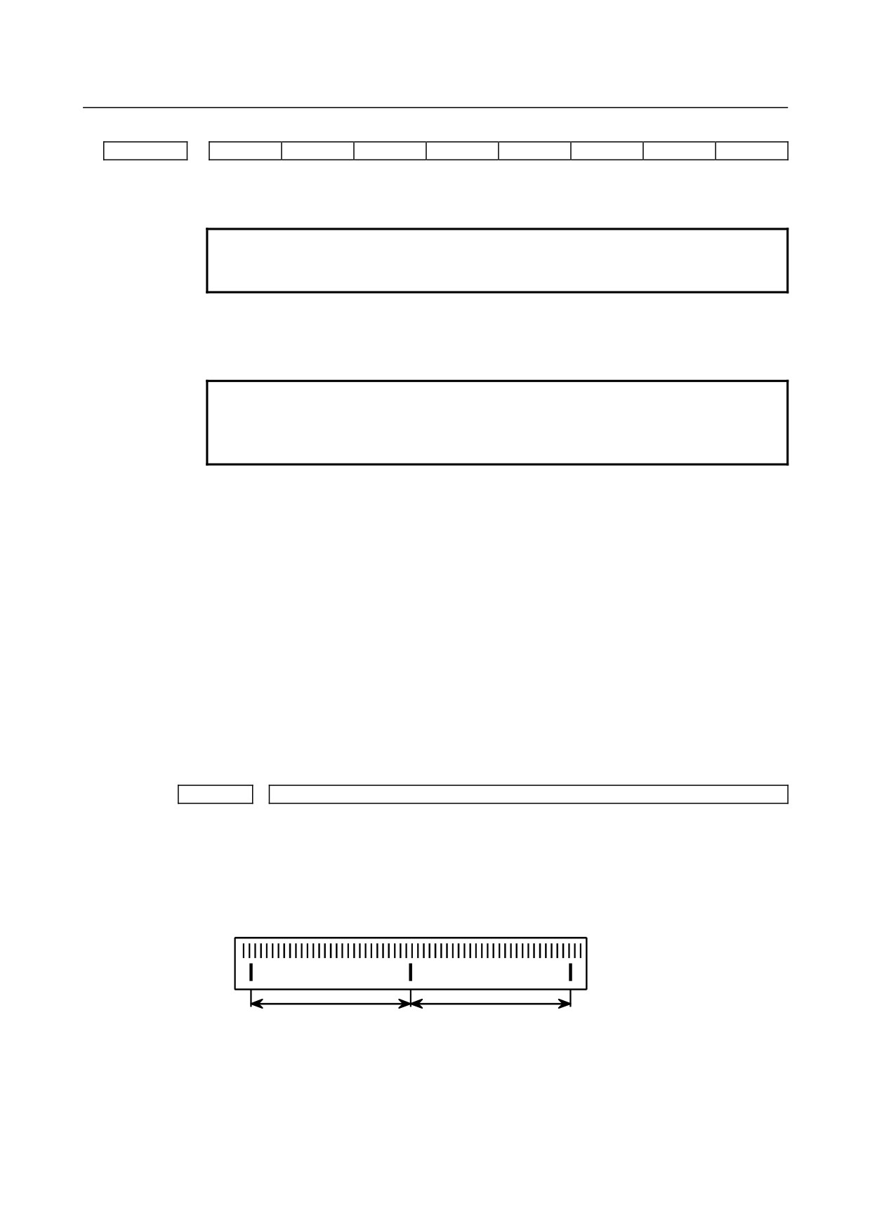
1821
Reference counter capacity per axis
[P]
Normally, the number of feedback pulses per motor revolution is set to the reference counter capacity.
* When plural reference marks are on a linear scale, a quotient of the distance between the reference
marks divided by an interfer may be used as a reference counter capacity:
(Example)
(1μm)
300mm ⇒ reference counter
30000
20000
15000
10000
etc
- 504 -
B-64485EN/01
8.DIGITAL SERVO
8.5
DOGLESS REFERENCE POSITION SETTING
When there are no dog nor limit switch for reference position return, this function enables the tool to
return the reference position that is set by MTB.
When the absolute position detector is used, the reference position once set remains also during power off.
When the absolute detector is replaced or absolute
position is lost, perform this setting.
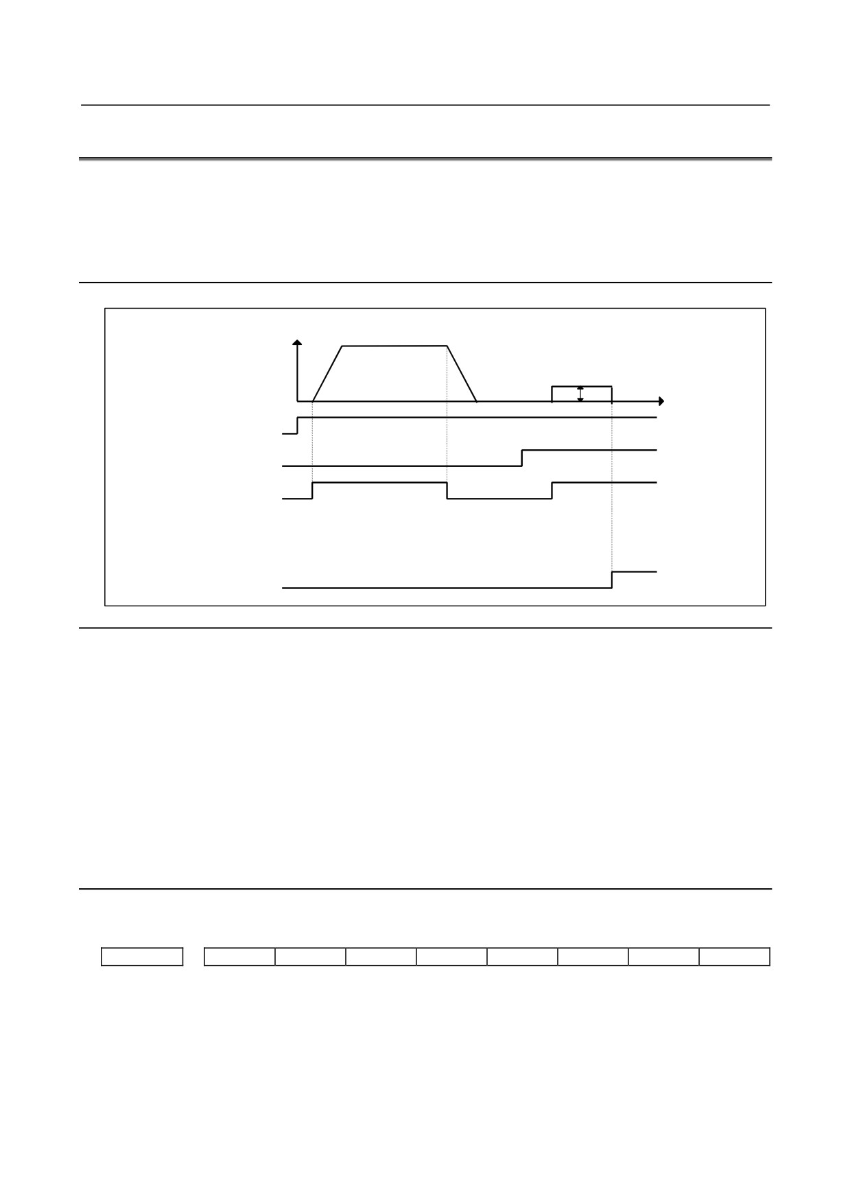
Overview
Speed
Reference position return
FL rate (PRM 1425)
Time
JOG
ZRN
+Jα
GRID
ZP α
Operation
<1> Move the tool along an axis for setting the reference position in the reference position return
direction in jog feed and position the tool near the reference position.
<2> Select the manual reference position return mode and set the feed axis and direction select signal (+
or - direction) for the axis for setting the reference position to 1.
<3> The tool is positioned at the nearest grid (electric grid based on the one-rotation signal of the
position detector) in the reference position return direction specified in bit 5 (ZMIx) of parameter No.
1006 from the current position. This position is set as the reference position.
<4> After the in-position status is confirmed, the reference position return completion signal (ZP1) and
reference position establishment signal (ZRF1) are set to 1.
* After the reference position has been set, select the reference position return mode (ZRN signal is 1)
and turn on an axis-and-direction- select signal, then the tool returns to the reference position.
Parameter
There are the following related parameters.
#7
#6
#5
#4
#3
#2
#1
#0
1005
DLZx
[Input type] Parameter input
[Data type] Bit axis
#1 DLZx Function for setting the reference position without dogs
0: Disabled
1: Enabled
- 505 -
8.DIGITAL SERVO
B-64485EN/01
#7
#6
#5
#4
#3
#2
#1
#0
1006
ZMIx
[Input type] Parameter input
[Data type] Bit axis
NOTE
When this parameter is set, the power must be turned off before
operation is continued.
#5 ZMIx The direction of manual reference position return is:
0:
+ direction
1:
- direction
8.6
αi SERVO WARNING INTERFACE
Overview
The αi servo system can report the warning status before one of the following target alarms occurs.
When the warning status is entered, a report to the PMC is issued.
For example, this signal can be used by the machine for retracting tools from the time a warning occurs
by the time a servo alarm occurs.
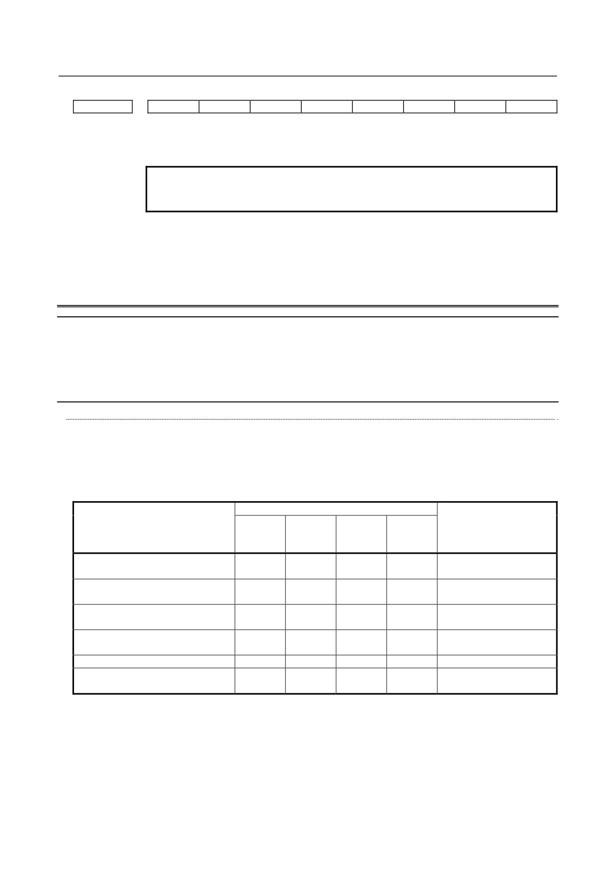
Signal
Servo warning detail signals SVWRN1 to 4 <F093.4 to 7>
[Classification] Output signal
[Function] Reports the warning signal corresponding to the state of the servo amplifier.
[Output condition] The following table shows the warning statuses of the servo amplifier and their
corresponding warning signals.
Warning status signals
Time from when a
SVWRN4
SVWRN3
SVWRN2
SVWRN1
warning state signal is
Corresponding alarm messages
<F093.7>
<F093.6>
<F093.5>
<F093.4>
issued to until an alarm
occurs
SV0444 SV INTERNAL FAN
1
0
0
0
One minute
FAILURE
SV0601 SV EXTERNAL FAN
1
0
0
1
Until overheat occurs
FAILURE
(inconstant)
SV0443 PS INTERNAL FAN
1
1
0
0
One minute
FAILURE
SV0606 PS EXTERNAL FAN
1
1
0
1
Until overheat occurs
FAILURE
(inconstant)
SV0431 PS OVERLOAD
1
1
1
0
One minute
SV0607 PS IMPROPER INPUT
1
1
1
1
PSR: Five seconds,
POWER
PS: One minute
- 506 -
B-64485EN/01
8.DIGITAL SERVO
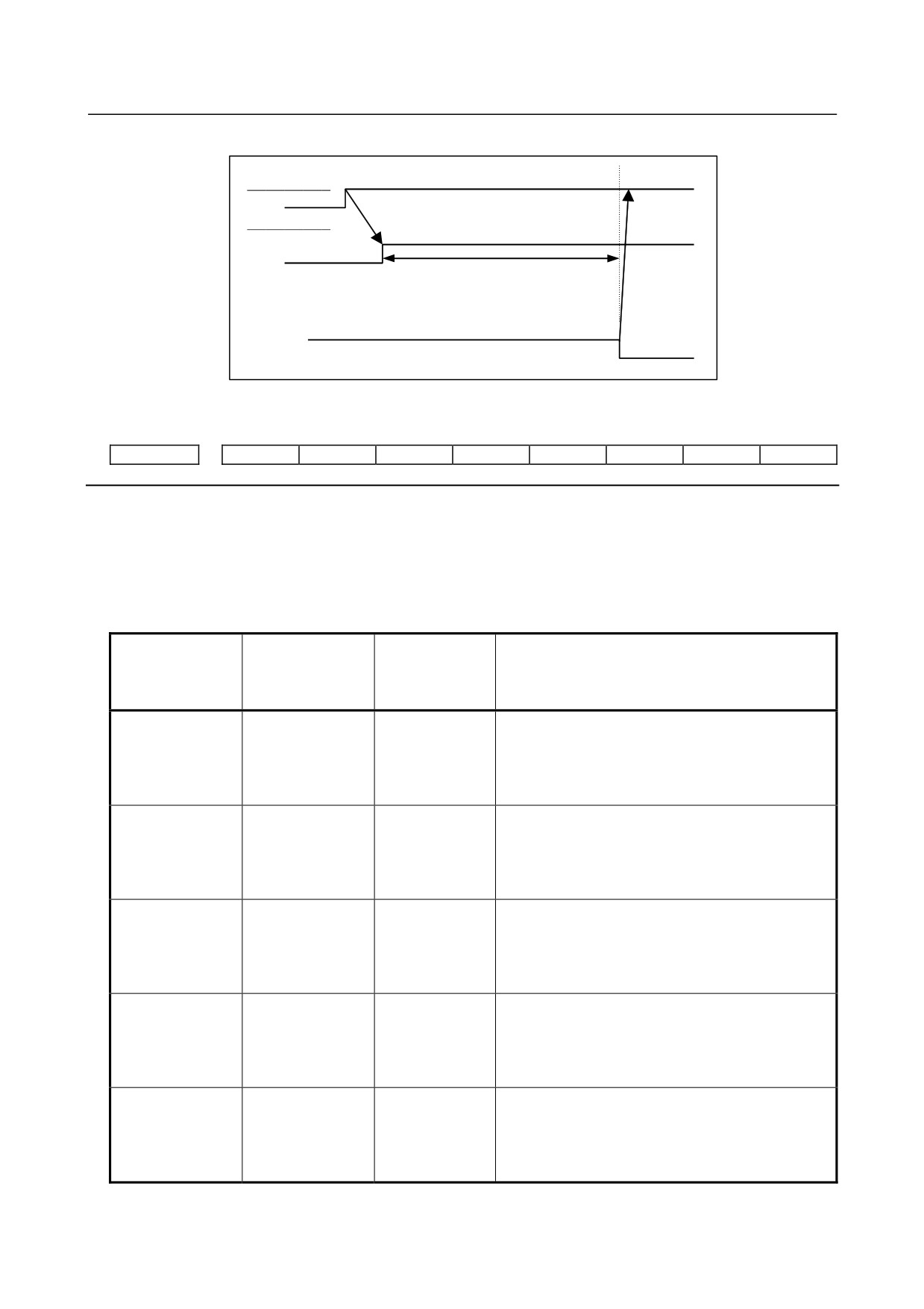
A timing chart for handling a warning is shown below.
Occurrence of a warning
Servo amplifier
SVWRN1-4
(Warning)
PMC
Perform deceleration stop or block stop
during this time period with the PMC to
stop the machine without damage. The
time period varies with the warning type.
Activation
Occurrence and stop of the alarm corresponding to a warning
Signal address
#7
#6
#5
#4
#3
#2
#1
#0
F093
SVWRN4
SVWRN3
SVWRN2
SVWRN1
SVS
Warning status alarms for αi servo amplifiers
When bit 2 (SWP) of parameter No. 1807 is set to 0, if an αi servo amplifier is placed in the warning
status, a DS alarm is output in addition to the servo warning detail signals.
If one of the following alarms is issued, automatic operation enters the feed hold state and movements
along all controlled axes including PMC axes are decelerated to a stop. Issuing a warning status alarm
does not cause the servo motor to be deactivated.
Alarm No. when
Alarm No. when
the servo
the servo
Operation performed when the warning status
Alarm message
amplifier is in the
amplifier is in the
occurs
warning status
alarm status
DS0608
SV0444
SV INTERNAL
Immediately after the fan stops, DS0608 is displayed
FAN FAILURE
and movements along axes enter the feed hold stop
state. The servo motor is kept active for 1 minute.
After that, the servo motor is deactivated and
SV0444 is displayed.
DS0609
SV0601
SV EXTERNAL
Immediately after the fan stops, DS0609 is displayed
FAN FAILURE
and movements along axes enter the feed hold stop
state. When bit 2 of parameter No. 1807 is set to 1
after that, the alarm display can be canceled by a
reset and operation can be restarted.
DS0610
SV0443
PS INTERNAL
Immediately after the fan stops, DS0610 is displayed
FAN FAILURE
and movements along axes enter the feed hold stop
state. The servo motor is kept active for 1 minute.
After that, the servo motor is deactivated and
SV0443 is displayed.
DS0611
SV0606
PS EXTERNAL
Immediately after the fan stops, DS0611 is displayed
FAN FAILURE
and movements along axes enter the feed hold stop
state. When bit 2 of parameter No. 1807 is set to 1
after that, the alarm display can be canceled by a
reset and operation can be restarted.
DS0612
SV0431
PS OVERLOAD
If the main circuit of the common power supply (PS)
is overloaded, DS0612 is displayed and movements
along axes enter the feed hold stop state. A certain
period of time after that, the servo motor is
deactivated and SV0441 is displayed.
- 507 -
8.DIGITAL SERVO
B-64485EN/01
Alarm No. when
Alarm No. when
the servo
the servo
Operation performed when the warning status
Alarm message
amplifier is in the
amplifier is in the
occurs
warning status
alarm status
DS0613
SV0607
PS IMPROPER
If the main power source for the common power
INPUT POWER
supply (PS) becomes abnormal, DS0613 is
displayed and movements along axes enter the feed
hold stop state.
After an alarm in the warning status listed above is issued, when the αi servo amplifier is actually placed
in the alarm status, the servo motor is deactivated and the number of an alarm in the alarm status is
additionally displayed.
When bit 2 (SWP) of parameter No. 1807 is set to 1, if an αi servo amplifier is placed in the warning
status, only the servo warning detail signals are output and no alarm in the warning status (alarm DS0608
to DS0613) is issued. If a servo amplifier is placed in the warning status during automatic operation,
automatic operation is kept. So, decelerate the movements along axes to a stop using the servo warning
detail signals before the servo motor is deactivated. Note that if the movements along axes are not
decelerated to a stop, the servo motor is suddenly deactivated during movement along axes.
Parameter
#7
#6
#5
#4
#3
#2
#1
#0
1807
SWP
[Input type] Parameter input
[Data type] Bit path
#2 SWP This parameter specifies the operation of the αi series servo amplifier in its warning state
(for example, with the fan stopped).
0: An alarm is issued when the amplifier is placed in the warning state. Automatic
operation enters the feed hold state and the servo axis is decelerated to a stop.
1: An alarm is not issued even when the amplifier is placed in the warning state.
Automatic operation is kept. The servo is deactivated if the amplifier shifts from the
warning state to the alarm state.
- 508 -
B-64485EN/01
8.DIGITAL SERVO
CAUTION
If operation is continued with the external fan stopped while bit 2
(SWP) of parameter No. 1807 is set to 1, the servo amplifier may
be overheated and "overheat alarm", "IPM alarm", or "VRDY off
alarm" may be issued depending on the operating conditions. If
such an alarm is issued, the amplifier is deactivated and the servo
motor is stopped by the dynamic brake, involving a risk of breaking
the workpiece or tool as the stop from high-speed rotation requires
an extended distance. The user should therefore understand that
the operation with bit 2 (SWP) of parameter No. 1807 set to 1 is a
temporary step to take before fan replacement. Once the fan has
stopped, be sure to replace the fan immediately and set bit 2
(SWP) of parameter No. 1807 back to 0.
If bit 2 (SWP) of parameter No. 1807 is set to 1, the warning text
"FAN" blinks on the NC screen to show that the external fan has
been stopped. Also on the machine side, monitor the warning signal
output to the PMC and remind the operator of the operation with the
fan stopped.
8.7
αi SERVO INFORMATION SCREEN
Overview
In the αi servo system, ID information output from each of the connected units is obtained and output to
the CNC screen.
The units that have ID information are shown below.
(Remark: Some instances of these units do not have ID information.)
-
Servo motor
-
Pulsecoder
-
Servo amplifier
-
Power supply
ID information is automatically read from each of the connected units during first startup of the CNC and
then recorded. Next time (and the subsequent time) the CNC is started, the ID information that can be
read is compared with one recorded at the first startup time in order to monitor any change to the
connected units. (If there is a difference between them, the alarm mark (*) appears.)
The recorded ID information can be edited. Therefore, the ID information of an unit that does not have ID
information can be displayed. (However, the alarm mark (*) indicating a difference between these IDs
appears.)
Parameter
#7
#6
#5
#4
#3
#2
#1
#0
11320
IDC
[Input type] Parameter input
[Data type] Bit path
- 509 -
8.DIGITAL SERVO
B-64485EN/01
#1 IDC The soft key [UPDATEALL ID], which updates ID information on the servo or spindle
information screen as a batch, is:
0: Not displayed.
1: Displayed.
NOTE
IDC is effective only if bit 0 (IDW) of parameter No. 13112 is set to
1.
#7
#6
#5
#4
#3
#2
#1
#0
13112
SVI
IDW
[Input type] Parameter input
[Data type] Bit path
#0 IDW Editing on the servo or spindle information screen is:
0: Prohibited.
1: Not prohibited.
#1 SVI The servo information screen is:
0: Displayed.
1: Not displayed.
Displaying the servo information screen
1
Press the
function key, then press the [SYSTEM] soft key.
2
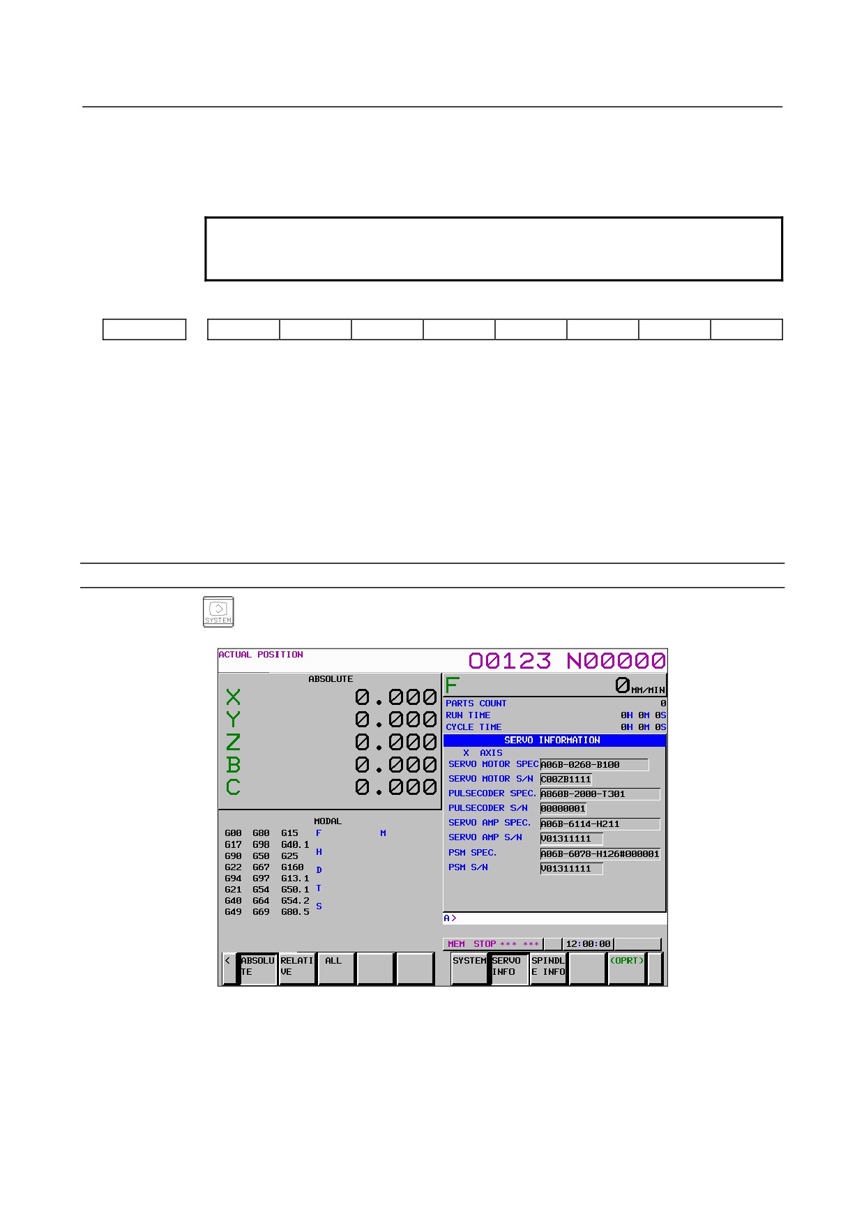
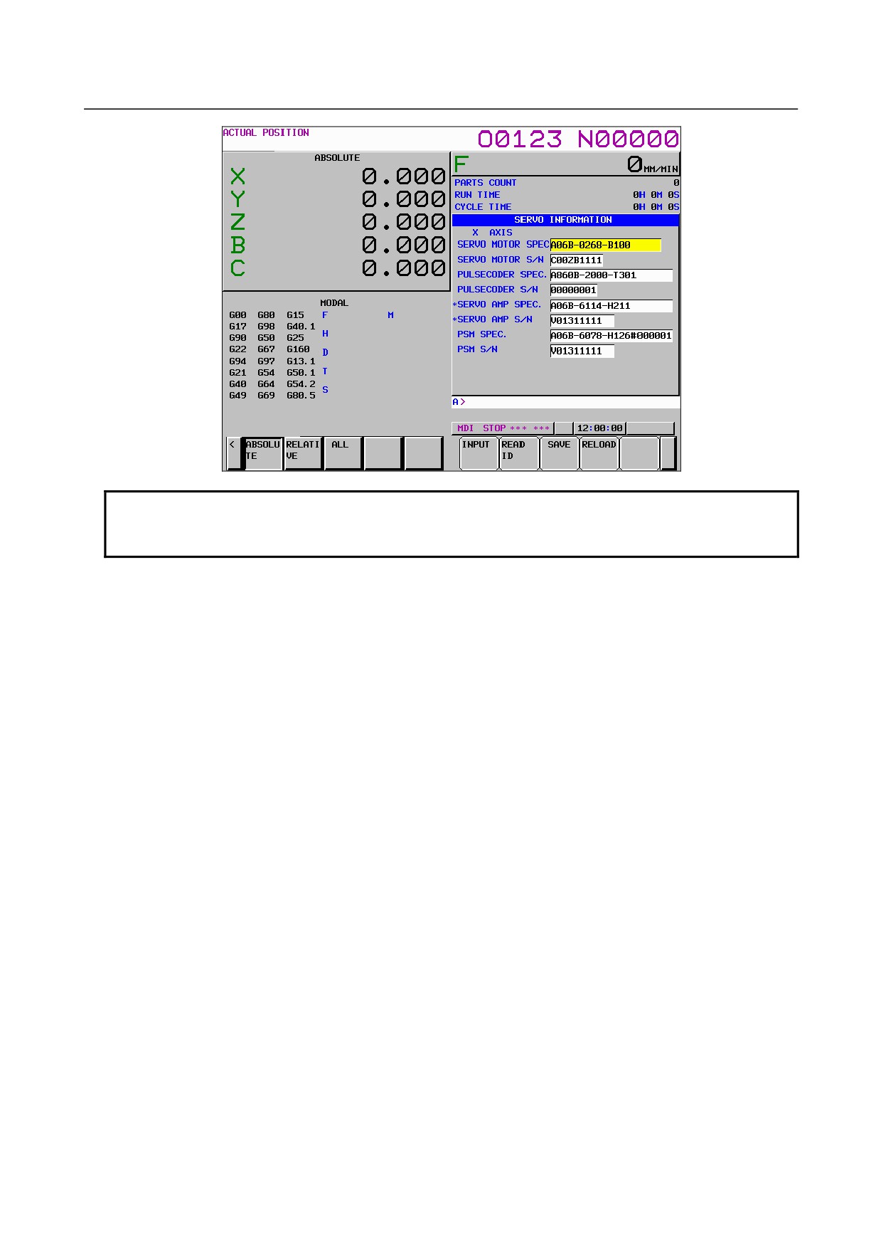
Press the [SERVO INFO] soft key to display the screen as shown below.
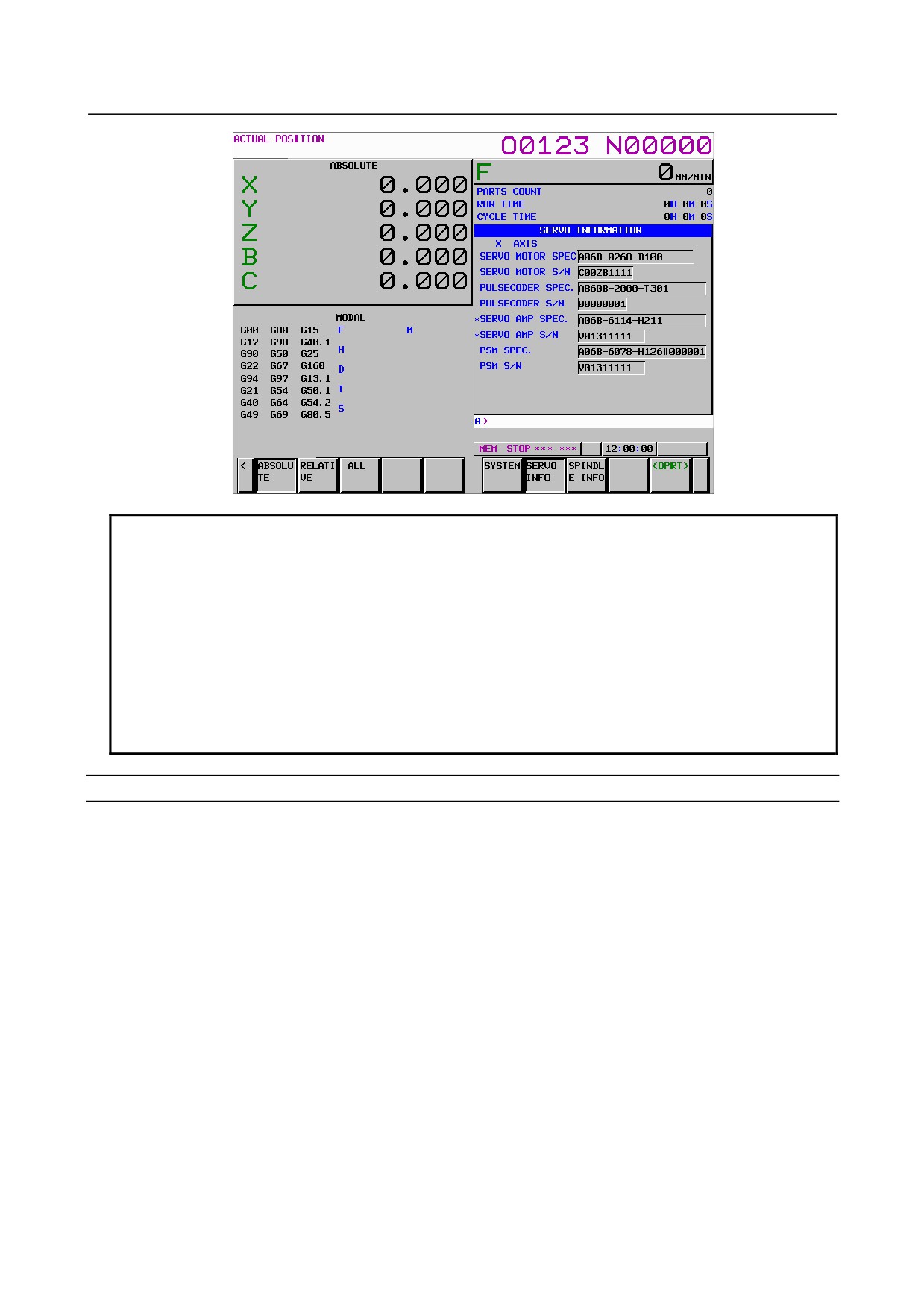
* Servo information is stored in flash ROM. If there is a difference between the ID information in
screen and the actual ID information, the corresponding items are preceded by *, as shown
below.
- 510 -
B-64485EN/01
8.DIGITAL SERVO
Additional Information
Even if replacement is performed reasonably such as for repairing, this function
incorrectly indicates the * mark when it detects the replacement.
To clear the * mark, follow the steps below to update the registered data, as
described in the editing section later.
(1) Make the registered data editable. (Bit 0 (IDW) of parameter No. 13112 = 1)
(2) On the edit screen, place the cursor on the item from which you want to
delete the * mark.
(3) Operate the soft keys [READ ID], [INPUT], and [SAVE] in that order.
To clear all * marks at a time, press soft key [UPDATEALL ID] (displayed when
bit 1 (IDC) of parameter No. 11320 is set to 1).
Editing the servo information screen
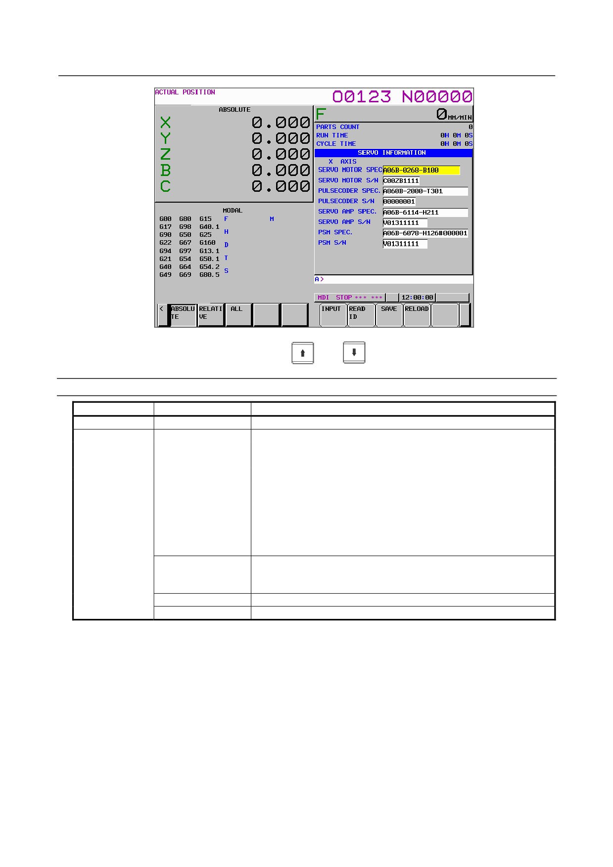
1
Assume that bit 0 (IDW) of parameter No. 13112 = 1 and bit 1 (IDC) of parameter No. 11320 = 1.
2
Press the MDI switch on the machine operator's panel.
3
Follow the steps shown in "Displaying the servo information screen" to display the screen as shown
below.
- 511 -
8.DIGITAL SERVO
B-64485EN/01
4
To move the cursor on the screen, use the
and
keys.
Screen operation
Mode
Key operation
Use
Viewing (*1)
Page key
Scrolls up or down on a screen-by-screen basis.
Editing (*2)
Soft key
[INPUT]
Replace the selected ID information at the cursor position with the
character string in key-in buffer.
[CANCEL]
Deletes the character string in key-in buffer.
[READ ID]
Transfers the ID information the connected device at the cursor has to
the key-in buffer. Only the items preceded by * (*3) are valid.
[SAVE]
Saves the ID information that has been changed on the servo information
screen in flash ROM.
[RELOAD]
Cancels the ID information that has been changed on the servo
information screen and loads ID information from flash ROM.
[UPDATEALL ID] (*1)
Updates the ID information for all axes that is output from each of the
connected units displayed on the servo or spindle information screen at a
time.
Page key
Scrolls up or down on a screen-by-screen basis.
Cursor key
Scrolls up or down the selection of ID information.
*1 Viewing mode: when bit 0 (IDW) of parameter No. 13112 = 0
*2 Editing mode: when bit 0 (IDW) of parameter No. 13112 = 1
*3 If there is a difference between the ID information in screen and the actual ID information, the
corresponding items are preceded by *.
*4 when bit 1 (IDC) of parameter No. 11320 = 1
- 512 -
B-64485EN/01
8.DIGITAL SERVO
NOTE
For axes that are not used by the αi servo system, ID information of connected
units cannot be obtained.
- 513 -
9.AC SPINDLE
B-64485EN/01
9 AC SPINDLE
This chapter outlines the serial interface spindle amplifiers and explains related parameters.
9.1 SERIAL INTERFACE AC SPINDLE
515
9.1.1 OUTLINE OF SPINDLE CONTROL
515
9.1.2 SPINDLE SETTING AND TUNING SCREEN
517
9.1.3 AUTOMATIC SETTING OF STANDARD PARAMETERS
524
9.1.4 WARNING INTERFACE
525
9.1.5 SPINDLE INFORMATION SCREEN
527
- 514 -
B-64485EN/01
9.AC SPINDLE
9.1
SERIAL INTERFACE AC SPINDLE
9.1.1
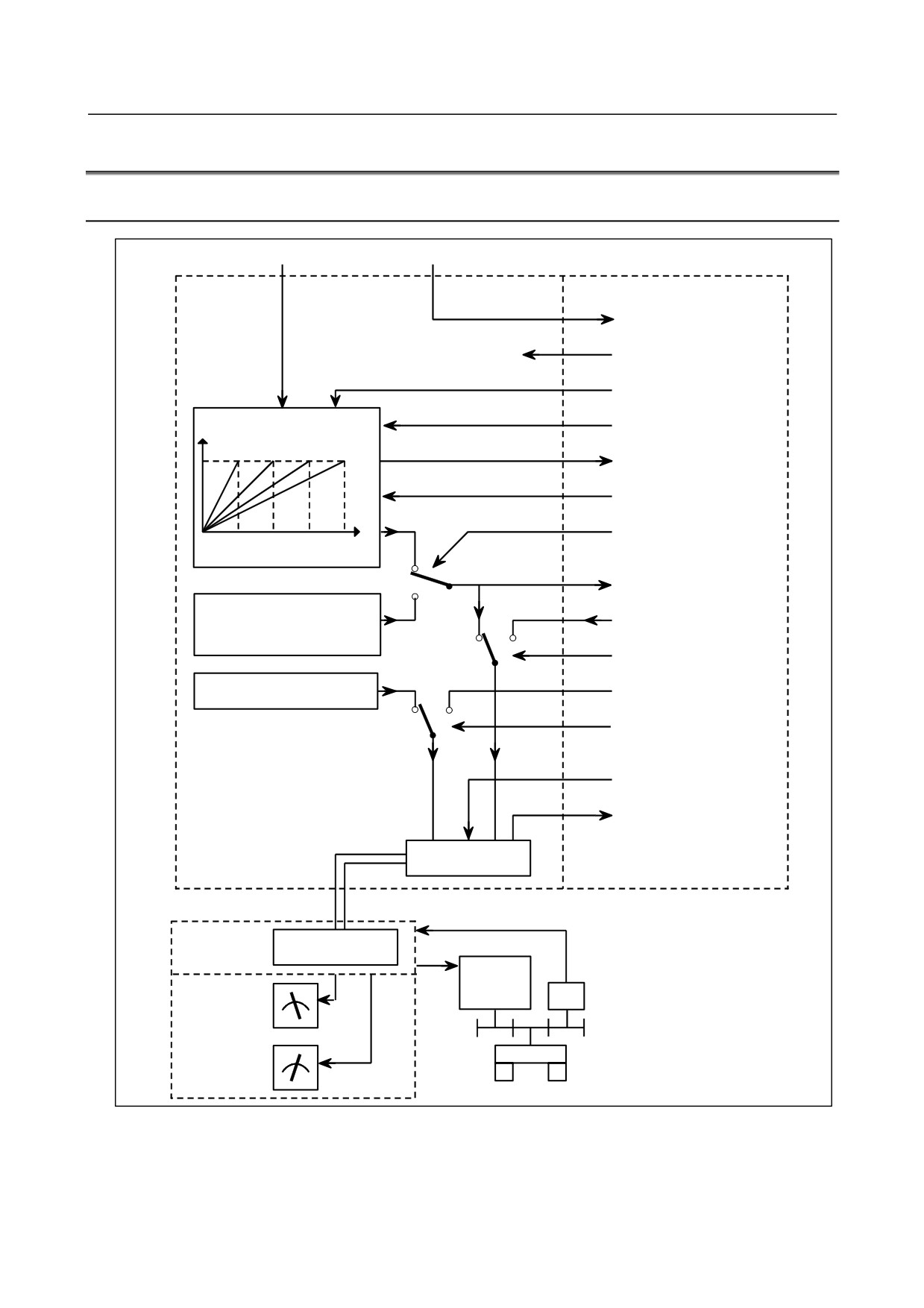
Outline of Spindle Control
S command
M command
NC
PMC
M03, M04, M05, M19
FIN
*SSTP (Spindle stop)
Motor speed
SOVx (Spindle override)
SF, GR1O, GR2O, GR3O
(For milling machining)
GR1, GR2 (For lathe cutting)
S
SOR (Orientation)
(Parameters Nos. 3735 to
3752)
0
R01O to R12O
1
Orientation speed
(bit 1 (ESF) of parameter No.3705,
R01I to R12I
parameter No.3732, and bit 5
0
1
(ORM) of parameter No.3706)
SIND
Output polarity (Bits 7 (CWM) and
SGN (0=+, 1=-)
6 (TCW) of parameter No.3706)
0
1
SSIN
*ESP, MRDY,
SFR, SRV, ORCM etc.
SST, SDT, SAR, LDT1, LDT2
ORAR, ALM etc.
Communication
function
Communication cable
Serial
spindle
Communication
amplifier
function
Spindle
Operator's panel
motor
PC
Load meter
LM
Speedometer
Spindle
SM
- 515 -
9.AC SPINDLE
B-64485EN/01
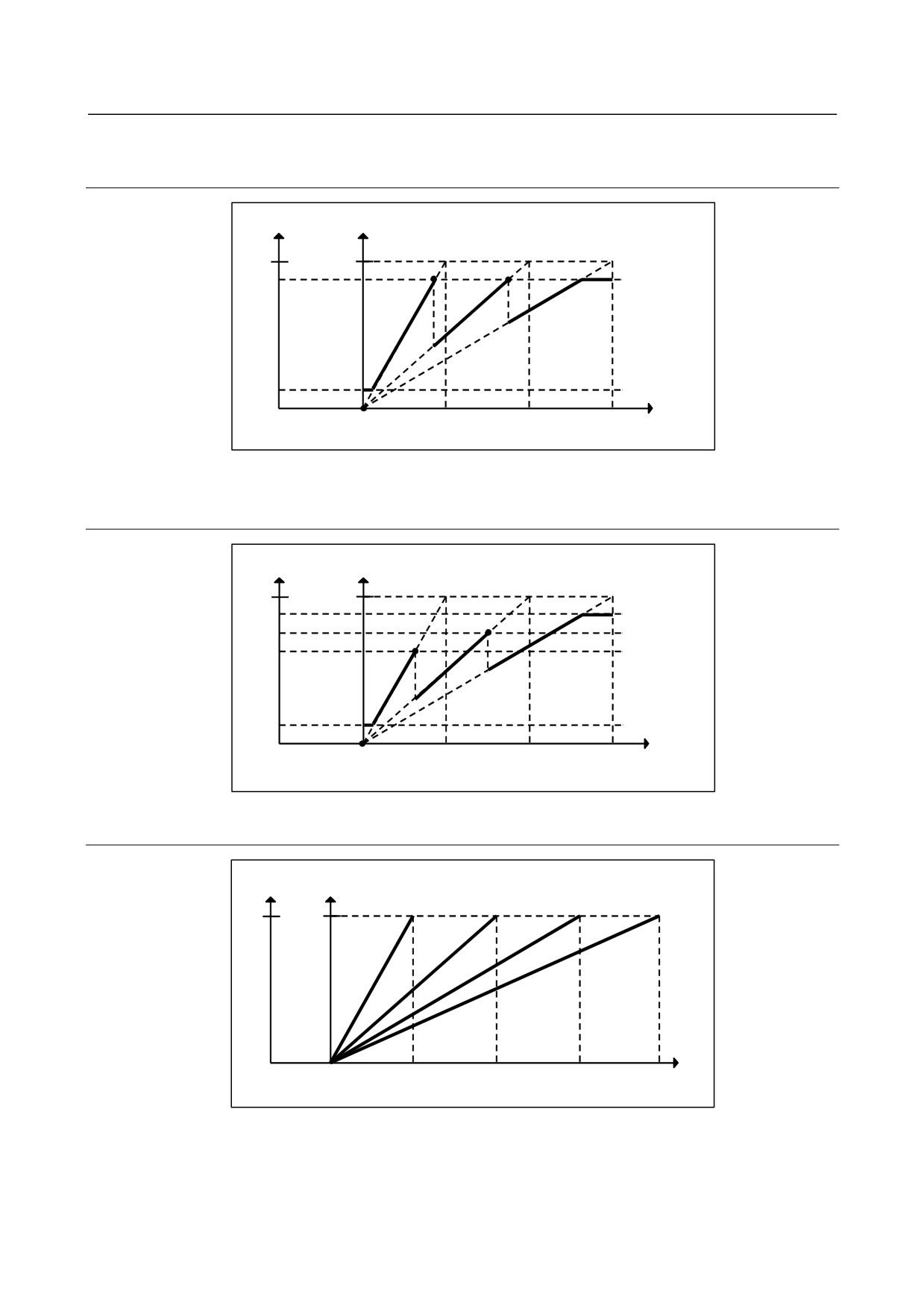
9.1.1.1 Method A of gear change for machining center system
(bit 2 (SGB) of Parameter No.3705 = 0)
Output
Motor speed
4095
Max
Parameter
Gear 2
Gear 3
No.3736
Gear 1
Parameter
No.3735
0
S code
0
Parameter
Parameter
Parameter
(min-1)
No.3741
No.3742
No.3743
9.1.1.2 Method B of gear change for machining center system
(bit 2 (SGB) of Parameter No.3705 = 1)
Output
Motor speed
Parameter
4095
Max
No.3736
Parameter
No.3752
Parameter
Gear 1
Gear 2
Gear 3
No.3751
Parameter
No.3735
0
S code
0
Parameter
Parameter Parameter
(min-1)
No.3741
No.3742
No.3743
9.1.1.3 Lathe system
Output Motor speed
4095
Max
Gear 1
Gear 2
Gear 3
Gear 4
S code
(min-1)
0
0
0
Parameter
Parameter Parameter Parameter
No.3741
No.3742
No.3743
No.3744
- 516 -
B-64485EN/01
9.AC SPINDLE
9.1.2
Spindle Setting and Tuning Screen
9.1.2.1 Display method
(1) Confirm the parameters
#7
#6
#5
#4
#3
#2
#1
#0
3111
SPS
[Input type] Setting input
[Data type] Bit path
#1 SPS 0: The spindle tuning screen is not displayed.
1: The spindle tuning screen is displayed.
(2) Press the function key
to select the screen for setting parameters and other data.
(3) Press the continuous menu key
(4) Press the soft key [SP.PRM]. Then, the spindle setting and tuning screen appears.
(5) The following screens are provided. These screens can be selected using soft keys.
<1> [SP.SET] : Spindle setting screen
<2> [SP.TUN] : Spindle tuning screen
<3> [SP.MON] : Spindle monitor screen
(6) With the page keys
, a spindle to be displayed can be selected (only when multiple
serial spindles are connected).
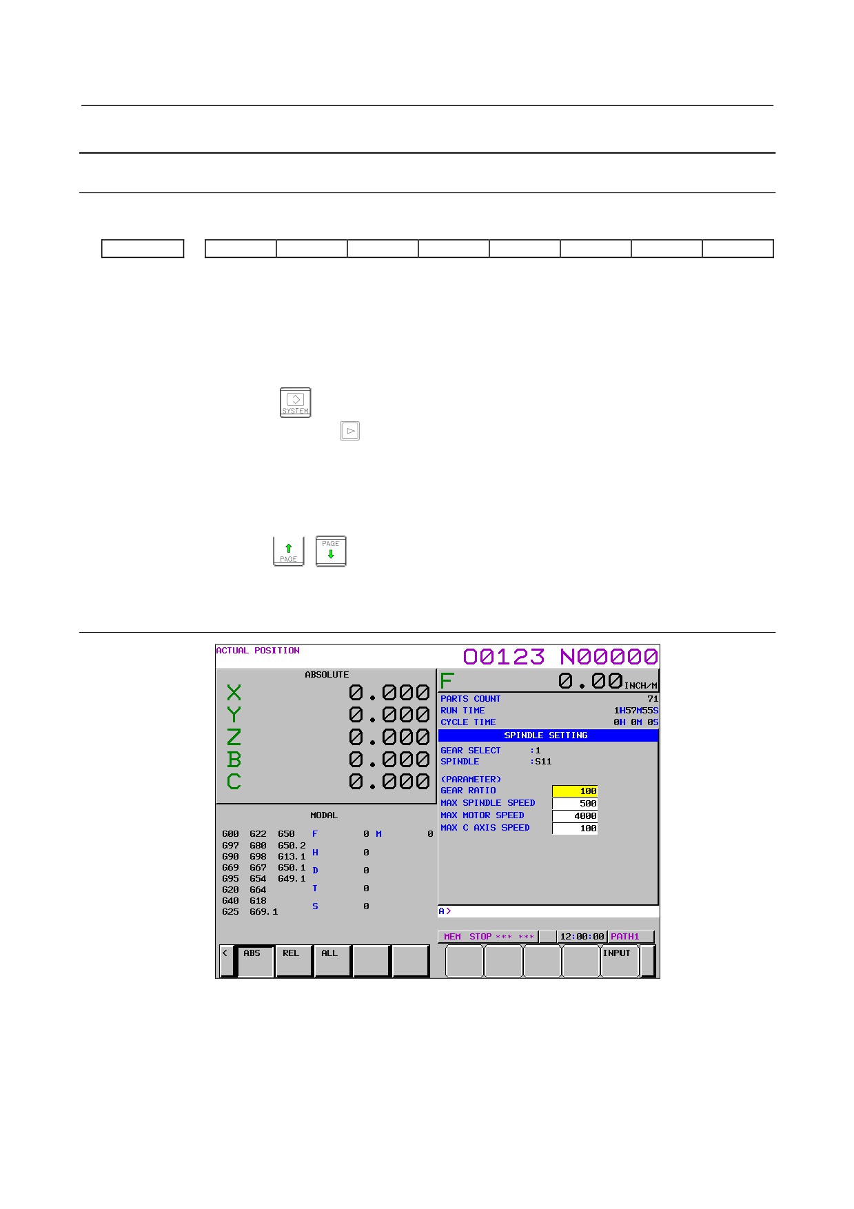
9.1.2.2 Spindle setting screen
- 517 -
9.AC SPINDLE
B-64485EN/01
-
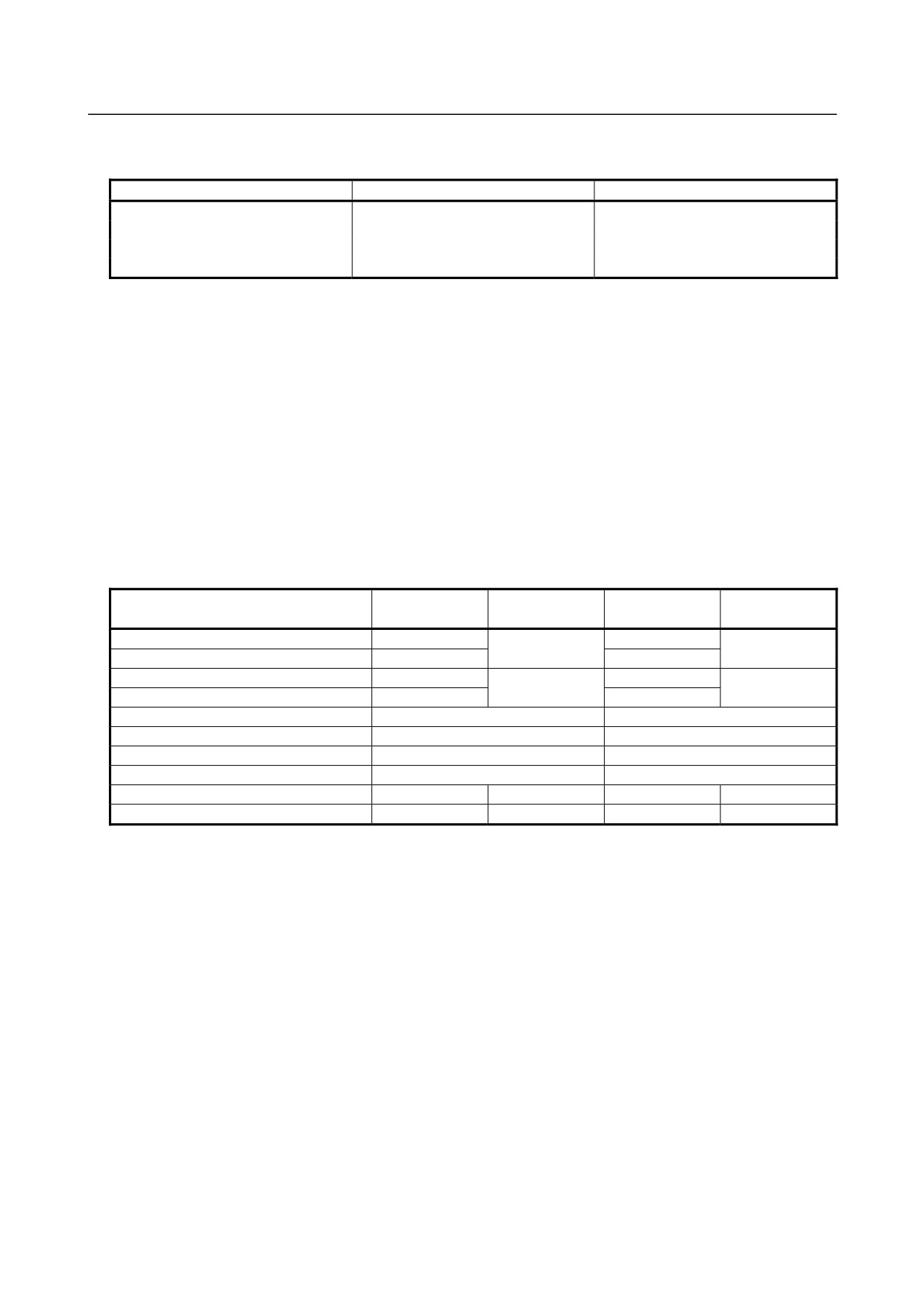
Gear selection
The gear select status on the machine side is displayed.
Indication
CTH1
CTH2
1
0
0
2
0
1
3
1
0
4
1
1
-
Spindle
Select a spindle for which data is to be set.
S11 :
Main spindle amplifier for the 1st spindle
S12 :
Subspindle amplifier for the 1st spindle
S21 :
Main spindle amplifier for the 2nd spindle
S22 :
Subspindle amplifier for the 2nd spindle
Switching between the main spindle and the subspindle is performed by spindle switching control.
Spindle switching control is the function for driving two spindle motors with one spindle amplifier. For
details, refer to the following manual.
Refer to the section related to “Spindle Switching Control” in the FANUC AC SPINDLE MOTOR αi /βi
series, FANUC BUILT-IN SPINDLE MOTOR Bi series PARAMETER MANUAL (B-65280EN).
-
Parameters
S11:
S12:
S21:
S22:
1st Main
1st Sub
2nd Main
2nd Sub
Gear ratio (HIGH)
4056
4056
4216
4216
Gear ratio (MEDIUM HIGH)
4057
4057
Gear ratio (MEDIUM LOW)
4058
4058
4217
4217
Gear ratio (LOW)
4059
4059
Max. spindle speed (gear1)
3741
3741
Max. spindle speed (gear2)
3742
3742
Max. spindle speed (gear3)
3743
3743
Max. spindle speed (gear4)
3744
3744
Max. motor speed
4020
4196
4020
4196
Max. C axis speed
4021
None
4021
None
- 518 -
B-64485EN/01
9.AC SPINDLE
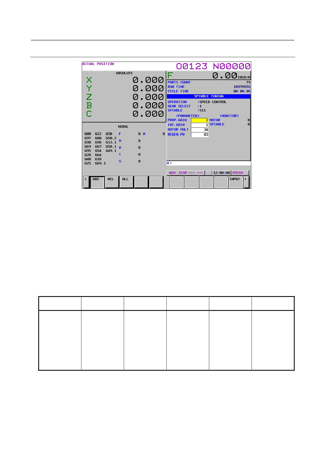
9.1.2.3 Spindle tuning screen
-
Operation mode
1
: SPEED CONTROL
2
: SPINDLE ORIENTATION
3
: SYNCHRONIZATION CONTROL
4
: RIGID TAPPING
5
: SP.CONTOURING CONTROL
6
: SP.POSITIONING CONTROL
-
Gear selection
-
Spindle
The descriptions of these two items are the same as those for the spindle setting screen.
-
Displayed parameters
The displayed parameters vary depending on the operation mode.
Spindle positioning
Synchronization
Normal operation
Orientation
Rigid tapping
Cs contour control
control
control
Proportional gain
Proportional gain
Proportional gain
Proportional gain
Proportional gain
Proportional gain
Integral gain
Integral gain
Integral gain
Integral gain
Integral gain
Integral gain
Loop gain
Motor voltage
Loop gain
Loop gain
Loop gain
Loop gain
Motor voltage
Regenerative power
Motor voltage
Motor voltage
Motor voltage
Motor voltage
ZRN gain (%)
ORAR gain (%)
Acceleration/
ZRN gain
ZRN gain (%)
Shift reference
Shift spindle stop
deceleration constant
Shift reference
Shift reference
position
position
(%)
position
position
Shift reference
Shift reference
position
position
*1) For the parameter numbers corresponding to the displayed parameter items, see Section
“Correspondence between operation mode and parameters on spindle tuning screen”.
- 519 -
9.AC SPINDLE
B-64485EN/01
-
Displayed monitoring items
The displayed monitoring items vary depending on the operation mode.
Spindle positioning
Synchronization
Normal operation
Orientation
Rigid tapping
Cs contour control
control
control
Motor speed
Motor speed
Motor speed
Motor speed
Motor speed
Motor speed
Feedrate
Spindle speed
Spindle speed
Spindle speed
Spindle speed
Spindle speed
Position deviation S
Position deviation S
Position deviation S1
Position deviation S
Position deviation S
Position deviation S2
Position deviation Z
Synchronous
Synchronous
deviation
deviation
*1)
|Spindle data|
Motor speed [min-1] =
× Max. motor speed (*)
16383
(*) Parameter No. 4020: Main spindle Parameter No. 4196: Subspindle
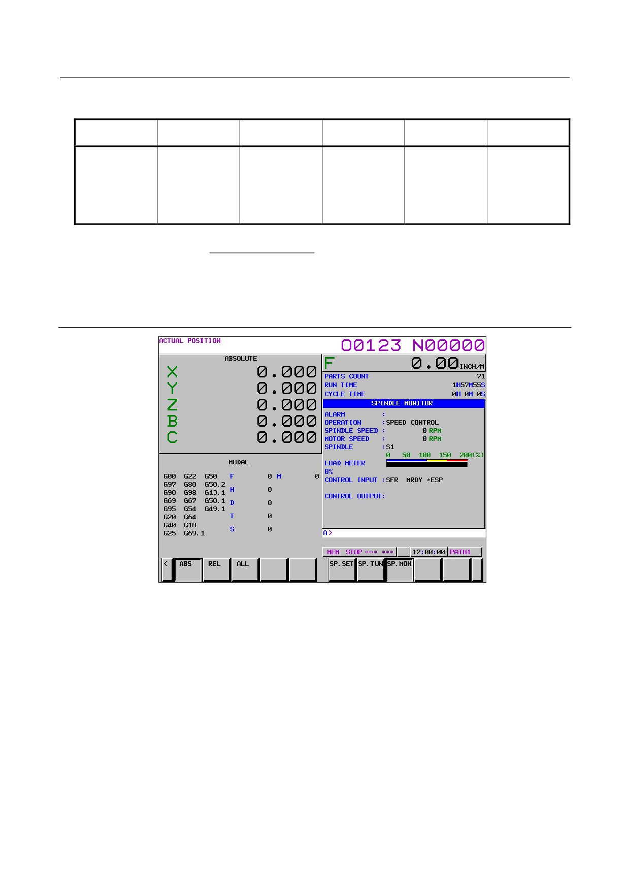
9.1.2.4 Spindle monitor screen
- 520 -

B-64485EN/01
9.AC SPINDLE
-
Spindle alarm
9001 :MOTOR OVERHEAT
9053 :ITP FAULT 2
9113 :PS EXTERNAL FAN FAILURE
9002 :EX DEVIATION SPEED
9054 :OVERCURRENT
9120 :COMMUNICATION DATA ERROR
9003 :DC-LINK FUSE IS BROKEN
9055 :ILLEGAL POWER LINE
9121 :COMMUNICATION DATA ERROR
9004 :PS IMPROPER INPUT POWER
9056 :COOLING FAN FAILURE
9122 :COMMUNICATION DATA ERROR
9006 :THERMAL SENSOR DISCONNECT
9057 :PS EXCESS-REGENERATION2
9123:SPINDLE SWITCH CIRCUIT
ERROR
9007 :OVER SPEED
9058 :PS OVERLOAD
9124:LEARNING CTRL ROTATION CMD
ERROR
9009 :OVERHEAT MAIN CIRCUIT
9059 :PS INTERNAL FAN FAILURE
9125:LEARNING CTRL COMP ORDER
ERROR
9011 :PS OVER VOLT. DC LINK
9061 :SEMI-FULL ERROR EXCESS
9127 :LEARNING CTRL PERIOD ERROR
9012 :OVERCURRENT POWER CIRCUIT
9065 :SERIAL SPINDLE ALARM
9128:SP SYNC VELOCITY ERROR
EXCESS
9013 :CPU DATA MEMORY FAULT
9066 :COM. ERROR BETWEEN SP AMPS
9129:SP SYNC POSITION ERROR
EXCESS
9014 :SOFTWARE SERIES MISMATCH
9067 :FSC/EGB COMMAND ERROR
9130:TORQUE TANDEM POLARITY
ERROR
9015 :SPINDLE SWITCHING FAULT
9069 :SAFETY SPEED OVER
9131:SPINDLE TUNING FUNCTION
ALARM
9016 :RAM ERROR
9070 :ILLEGAL AXIS DATA
9132 :SER.SENSOR DATA ERROR
9017 :ID NUMBER PARITY ERROR
9071 :SAFETY PARAMETER ERROR
9133 :SER.SENSOR TRANSFER ERROR
9018:SUMCHECK ERROR PROGRAM
9072:MISMATCH RESULT OF MOTOR
9134:SER.SENSOR SOFT PHASE
ROM
SPEED CHECK
ERROR
9019 :EXCESS OFFSET CURRENT U
9073 :MOTOR SENSOR DISCONNECTED
9135 :SAFETY SPEED ZERO ERROR(SP)
9020 :EXCESS OFFSET CURRENT V
9074 :CPU TEST ERROR
9136:MISMATCH RESULT OF SAFETY
SPEED ZERO CHECK(SP)
9021 :POS SENSOR POLARITY ERROR
9075 :CRC ERROR
9137:SP DEVICE COMMUNICATION
ERROR
9022 :SP AMP OVER CURRENT
9076:INEXECUTION OF SAFETY
9139 :SER.SENSOR PULSE MISS
FUNCTIONS
9024 :SERIAL TRANSFER ERROR
9077:MISMATCH RESULT OF AXIS
9140 :SER.SENSOR COUNT MISS
NUMBER CHECK
9027 :DISCONNECT POSITION CODER
9078:MISMATCH RESULT OF SAFETY
9141 :SER.SENSOR NO 1-ROT SIGNAL
PARAMETER CHECK
9029 :OVERLOAD
9079 :INITIAL TEST ERROR
9142 :SER.SENSOR ABNORMAL
9030 :OVERCURRENT
9080 :ALARM AT THE OTHER SP AMP.
9143:CS HIGH SPEED CHANGE CMD
ERROR
9031 :MOTOR LOCK
9081 :1-ROT MOTOR SENSOR ERROR
9144:CURRENT DETECT CIRCUIT
ERROR
9032 :SIC-LSI RAM FAULT
9082 :NO 1-ROT MOTOR SENSOR
9145 :LOW VOLTAGE DRIVER
9033 :PS PRE-CHARGE FAILURE
9083 :MOTOR SENSOR SIGNAL ERROR
9146 :SP:INTERNAL OVERHEAT
9034 :ILLEGAL PARAMETER
9084 :SPNDL SENSOR DISCONNECTED
9147 :SP:GROUND FAULT
9036 :OVERFLOW ERROR COUNTER
9085 :1-ROT SPNDL SENSOR ERROR
9200 :PS GROUND FAULT
9037:ILLEGAL SETTING VELOCITY
9086 :NO 1-ROT SPNDL SENSOR
9201 :PS OVERCURRENT 2
DETECTOR
9041:ILLEGAL 1REV SIGN OF
9087 :SPNDL SENSOR SIGNAL ERROR
9202 :PS OVERCURRENT 3
POSITION CODER
9042:NO 1REV SIGN OF POSITION
9088 :COOLING RADI FAN FAILURE
9203 :PS OVERCURRENT 4
CODER
9043:DISCONNECT POSITION CODER
9089 :SUB MODULE SM (SSM) ERROR
9204 :PS SOFT THERMAL
DEF. SPEED
9046:ILLEGAL 1REV SIGN OF SCREW
9090 :UNEXPECTED ROTATION
9205 :PS OVER VOLT. DC LINK 2
CUT
9047:ILLEGAL SIGNAL OF POSITION
9091 :POLE POSITION COUNT MISS
9206 :PS OVER VOLT. DC LINK 3
CODER
9049 :DEF. SPEED IS OVER VALUE
9092:OVER SPEED TO VELOCITY
9207 :PS OVER VOLT. DC LINK 4
COMMAND
9050:SYNCRONOUS VALUE IS OVER
9110 :AMP COMMUNICATION ERROR
SPEED
9051 :PS LOW VOLT. DC LINK
9111:PS LOW VOLT. CONTROL
9052 :ITP FAULT 1
9112 :PS EXCESS-REGENERATION1
-
Operation
Following 6 modes are available:
a.
Normal operation
b.
Orientation
c.
Synchronous operation
d.
Rigid tapping
e.
Cs contour control
f.
Spindle positioning control
- 521 -