FANUC Series 30i-MODEL B, 31i-MODEL B, 32i-MODEL B. MAINTENANCE MANUAL - page 16

6.INTERFACE BETWEEN CNC AND PMC
B-64485EN/01
Address
Bit number
7
6
5
4
3
2
1
0
Fn377
SVSAR8#SV
SVSAR7#SV
SVSAR6#SV
SVSAR5#SV
SVSAR4#SV
SVSAR3#SV
SVSAR2#SV
SVSAR1#SV
~
Fn395
Fn396
Fn397
Fn398
Fn399
Fn400
SUCLPD#SP
SUCLPC#SP
SUCLPB#SP
Fn401
SCLPD#SP
SCLPC#SP
SCLPB#SP
Fn402
MSPOSD#SP
MSPOSC#SP
MSPOSB#SP
Fn403
SYNER#P
Fn404
COSP4#P
COSP3#P
Fn405
Fn406
Fn407
Fn408
Fn409
Fn410
Fn411
Fn412
Fn413
Fn414
Fn415
Fn416
- 432 -

B-64485EN/01
6.INTERFACE BETWEEN CNC AND PMC
Address
Bit number
7
6
5
4
3
2
1
0
Fn417
Fn418
~
Fn511
Fn512
MCSP#P
MCRQ#P
MCEXE#P
Fn513
ZRNR#P
DNCIR#P
MD4R#P
MD2R#P
MD1R#P
Fn514
MCEX8#P
MCEX7#P
MCEX6#P
MCEX5#P
MCEX4#P
MCEX3#P
MCEX2#P
MCEX1#P
Fn515
MCEX16#P
MCEX15#P
MCEX14#P
MCEX13#P
MCEX12#P
MCEX11#P
MCEX10#P
MCEX9#P
Fn516
MSEMI8#SV
MSEMI7#SV
MSEMI6#SV
MSEMI5#SV
MSEMI4#SV
MSEMI3#SV
MSEMI2#SV
MSEMI1#SV
Fn517
RP18#SV
RP17#SV
RP16#SV
RP15#SV
RP14#SV
RP13#SV
RP12#SV
RP11#SV
Fn518
RP28#SV
RP27#SV
RP26#SV
RP25#SV
RP24#SV
RP23#SV
RP22#SV
RP21#SV
Fn519
PTOFS#P
PTRDY#P
PTCVA#P
PTCNV#P
PTMOD#P
Fn520
ATBK
ACDEC#P
SVREV8
SVREV7
SVREV6
SVREV5
SVREV4
SVREV3
SVREV2
SVREV1
Fn521
SPP8
SPP7
SPP6
SPP5
SPP4
SPP3
SPP2
SPP1
Fn522
Fn523
Fn524
Fn525
SSYO4#SP
SSYO3#SP
SSYO2#SP
SSYO1#SP
SGNO4#SP
SGNO3#SP
SGNO2#SP
SGNO1#SP
~
Fn531
TDIACK
TDICHK
MMDISL
Fn532
SYNO8#SV
SYNO7#SV
SYNO6#SV
SYNO5#SV
SYNO4#SV
SYNO3#SV
SYNO2#SV
SYNO1#SV
Fn533
Fn534
Fn535
WFLN2
WFLN1
WETF
WETE
WECCS
WIOCH3
WIOCH2
WIOCH1
Fn540
TDIH4FE
TDIH3FE
TDIH2FE
TDIH1FE
TDIT4FE
TDIT3FE
TDIT2FE
TDIT1FE
- 433 -
6.INTERFACE BETWEEN CNC AND PMC
B-64485EN/01
Address
Bit number
7
6
5
4
3
2
1
0
Fn541
TDIO6FE
TDIO5FE
TDIO4FE
TDIO3FE
TDIO2FE
TDIO1FE
Fn542
TDIH4AE
TDIH3AE
TDIH2AE
TDIH1AE
TDIT4AE
TDIT3AE
TDIT2AE
TDIT1AE
Fn543
TDIO6AE
TDIO5AE
TDIO4AE
TDIO3AE
TDIO2AE
TDIO1AE
~
Fn545
OVLNS#P
Fn546
CSMC4#SP
CSMC3#SP
CSMC2#SP
CSMC1#SP
~
Fn553
PHERD#P
PHERC#P
PHERB#P
PHERA#P
~
Fn767
- 434 -

B-64485EN/01
7.EMBEDDED ETHERNET FUNCTION
7 EMBEDDED ETHERNET FUNCTION
This chapter describes the specifications of the embedded Ethernet function.
Chapter 8, "EMBEDDED ETHERNET FUNCTION", consists of the following sections:
7.1 EMBEDDED ETHERNET PORT AND PCMCIA ETHERNET CARD
435
7.2 SETTING UP THE EMBEDDED ETHERNET FUNCTION
437
7.3 SWITCHING BETWEEN THE EMBEDDED ETHERNET DEVICES
466
7.4 EMBEDDED ETHERNET OPERATIONS
466
7.5 RESTART OF THE EMBEDDED ETHERNET
470
7.6 MAINTENANCE SCREEN FOR EMBEDDED ETHERNET FUNCTION
471
7.7 LOG SCREEN OF THE EMBEDDED ETHERNET FUNCTION
474
7.1
EMBEDDED ETHERNET PORT AND PCMCIA ETHERNET
CARD
The embedded Ethernet function can be used by selecting one of two types of devices: the embedded
Ethernet port and PCMCIA Ethernet card.
A selection can also be made to stop the embedded Ethernet function.
The PCMCIA Ethernet card is to be inserted into the memory card slot for temporary communication.
CAUTION
1 When using the embedded Ethernet function for the first time, set an IP address
and other items carefully as instructed by the network administrator, then
perform a sufficient communication test.
Note that an incorrect IP address or other setting may cause a communication
failure on the entire network.
2 A unit such as a PC situated in the same network can increase the
communication processing load on the CNC even if the unit is not
communicating with the CNC.
Avoid connecting the CNC to a factory-wide network. Use a router or the like to
separate the network including the CNC from the other networks.
NOTE
1 The embedded Ethernet port of Series 32i is available as an option.
2 Use the PCMCIA Ethernet card designated by FANUC. General Ethernet cards
available on the market cannot be used.
3 The PCMCIA Ethernet card is used for FANUC LADDER-III or SERVO GUIDE.
4 Use the PCMCIA Ethernet card just for temporary communication as described
above. Avoid using the card for continuous communication.
5 The PCMCIA Ethernet card is inserted into a memory card slot, with a part of the
card left uninserted. When using the PCMCIA Ethernet card, take great care not
to damage the card by hitting the protruding part of the card.
When the card becomes unnecessary, remove the card immediately, in order to
prevent any damage to the card.
- 435 -
7.EMBEDDED ETHERNET FUNCTION
B-64485EN/01
Related NC parameters
#7
#6
#5
#4
#3
#2
#1
#0
14880
ETH
[Input type] Parameter input
[Data type] Bit
#0 ETH The embedded Ethernet function (embedded Ethernet port or PCMCIA Ethernet card) is:
0: Used.
1: Not used.
NOTE
When this parameter is set, the power must be turned off before
operation is continued.
Selection of embedded Ethernet with the stand-alone type Series 30i /31i /32i with display unit with
14896
Windows CE
NOTE
When this parameter is set, the power must be turned off before
operation is continued.
[Input type] Parameter input
[Data type] Word
[Valid data range] 0 to 3
Set embedded Ethernet usable with the stand-alone type Series 30i /31i /32i with display
unit with Windows CE.
0 : For the embedded Ethernet port, the connector (CD38A) for Ethernet on the control unit
is used.
For the PCMCIA Ethernet card, the card slot on the side of the display unit is used.
1 : For the embedded Ethernet port, the connector (CD38A) for Ethernet on the control unit
is used.
For the PCMCIA Ethernet card, the card slot (CNM1B) on the control unit is used.
2 : For the embedded Ethernet port, the connector (CD38S) for Ethernet on the rear of the
display unit is used.
For the PCMCIA Ethernet card, the card slot on the side of the display unit is used.
3 : For the embedded Ethernet port, the connector (CD38S) for Ethernet on the rear of the
display unit is used.
For the PCMCIA Ethernet card, the card slot (CNM1B) on the control unit is used.
No.14896
embedded Ethernet port
PCMCIA Ethernet card
0
Port in the CNC
Memory card slot on a side of the display unit
1
Port in the CNC
Memory card slot in the CNC
2
Port in the rear of the display unit
Memory card slot on a side of the display unit
3
Port in the rear of the display unit
Memory card slot in the CNC
Notes on using Ethernet with display unit with Windows CE
The Ethernet interface on display unit with Windows CE may be used by both of the embedded Ethernet
function of the CNC and application software on Windows CE.
Note that the restrictions below are imposed accordingly.
- 436 -
B-64485EN/01
7.EMBEDDED ETHERNET FUNCTION
NOTE
1
When the LCD-mounted type Series 30i /31i /32i with Windows CE is used and
the PCMCIA Ethernet card is selected for the embedded Ethernet function,
application software on Windows CE cannot use the embedded Ethernet port.
When the embedded Ethernet port is selected for the embedded Ethernet
function, application software on Windows CE cannot use the PCMCIA Ethernet
card.
2
When the stand-alone type Series 30i /31i /32i with display unit with Windows
CE is used, the connection location of the embedded Ethernet function varies
according to the setting of NC parameter No. 14896. So, the restrictions below
are applied to the Ethernet interface on Windows CE.
(1) When 0 is set in NC parameter No. 14896 and the PCMCIA Ethernet card is
selected for the embedded Ethernet function, application software on
Windows CE cannot use the embedded Ethernet port.
(2) When 1 is set in NC parameter No. 14896, application software on Windows
CE can use the embedded Ethernet port and PCMCIA Ethernet card.
(3) When 2 is set in NC parameter No. 14896, the restriction on item 1 above
(for the LCD-mounted type) is applied.
(4) When 3 is set in NC parameter No. 14896 and the embedded Ethernet port
is selected for the embedded Ethernet function, application software on
Windows CE cannot use the PCMCIA Ethernet card.
3
When the Series 30i /31i /32i with Windows CE is used, application software on
Windows CE can perform communication simultaneously on a port (embedded
Ethernet port or PCMCIA Ethernet card) selected for the embedded Ethernet
function.
7.2
SETTING UP THE EMBEDDED ETHERNET FUNCTION
This section describes the setting of parameters for the embedded Ethernet function.
7.2.1
Setting of the FOCAS2/Ethernet Function
This subsection describes the settings required to operate the FOCAS2/Ethernet function.
Notes on using the FOCAS2/Ethernet function for the first time
NOTE
1 When running user's original application software created by using the
FOCAS2/Ethernet function, use the embedded Ethernet port.
2 The FOCAS2/Ethernet function allows up to five FOCAS2/Ethernet clients to be
connected to one CNC.
3 Concurrent access by multiple applications or personal computers may overload
the CNC, reducing the communication speed.
- 437 -
7.EMBEDDED ETHERNET FUNCTION
B-64485EN/01
7.2.1.1 Operation on the FOCAS2/Ethernet setting screen
On the Ethernet parameter setting screen, set the parameters for operating the FOCAS2/Ethernet function.
Procedure
1
Press the function key
2
Soft keys [EMBED PORT] and [PCMCIA LAN] appear.
(When there is no soft keys, press the continue key.)
3 To display the Ethernet Setting screen for the embedded Ethernet port or the PCMCIA Ethernet card,
press soft key [EMBED PORT] or [PCMCIA LAN], respectively.
4
Press soft keys [COMMON] and [FOCAS2] and then enter parameters for the items that appear.
NOTE
1 The parameters for the embedded Ethernet port and the parameters for the
PCMCIA Ethernet card are independent of each other.
2 The settings of the FOCAS2/Ethernet function for the PCMCIA Ethernet card are
made when a connection to SERVO GUIDE and FANUC LADDER-III is
established.
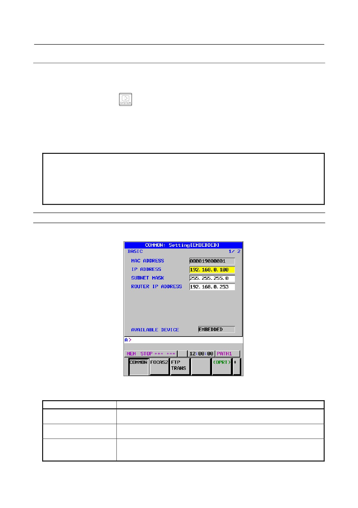
COMMON screen (BASIC)
Press soft key [COMMON]. The COMMON screen (BASIC) is displayed.
COMMON screen (BASIC)
Setting items
Item
Description
IP ADDRESS
Specify the IP address of the embedded Ethernet.
(Example of specification format: "192.168.0.100")
SUBNET MASK
Specify a mask address for the IP addresses of the network.
(Example of specification format: "255.255.255.0")
ROUTER IP ADDRESS
Specify the IP address of the router.
Specify this item when the network contains a router.
(Example of specification format: "192.168.0.253")
- 438 -
B-64485EN/01
7.EMBEDDED ETHERNET FUNCTION
Display items
Item
Description
MAC ADDRESS
Embedded Ethernet MAC address
AVAILABLE DEVICE
Enabled device of the embedded Ethernet.
Either the embedded Ethernet port or the PCMCIA Ethernet card is displayed.
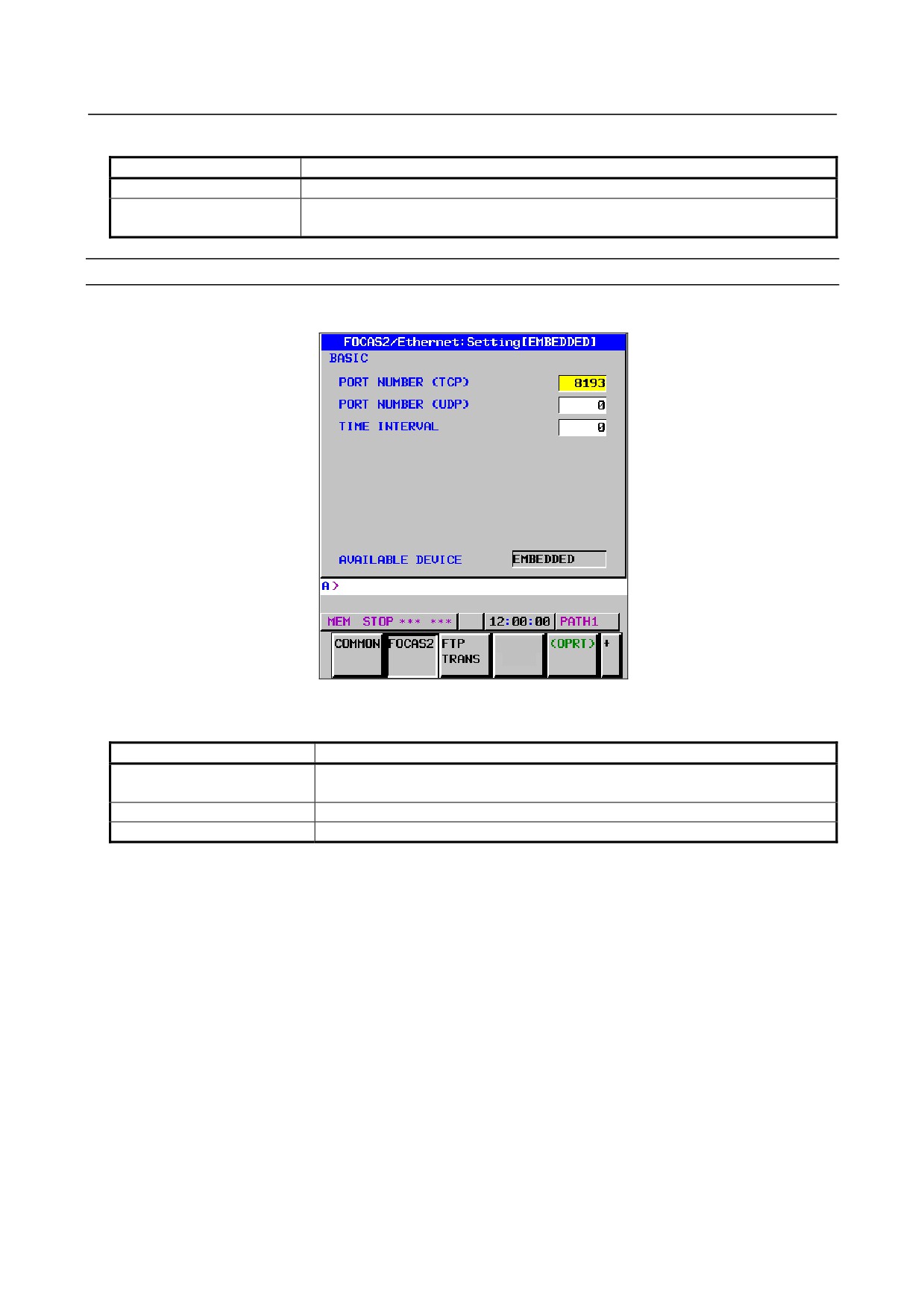
FOCAS2 screen
Press soft key [FOCAS2]. The FOCAS2 screen is displayed.
FOCAS2 screen
Setting items
Item
Description
PORT NUMBER (TCP)
Specify a port number to be used with the FOCAS2/Ethernet function. The valid
input range is 5001 to 65535.
PORT NUMBER (UDP)
Set this item to 0 when it is used as the FOCAS2/Ethernet function.
TIME INTERVAL
Set this item to 0 when it is used as the FOCAS2/Ethernet function.
Initial setting of the PCMCIA Ethernet card
The PCMCIA Ethernet card is factory-set to the following standard setting values, for ease of connection
with SERVO GUIDE or FANUC LADDER-III.
IP ADDRESS
: 192.168.1.1
SUBNET MASK
: 255.255.255.0
ROUTER IP ADDRESS
: None
PORT NUMBER (TCP)
: 8193
PORT NUMBER (UDP)
: 0
TIME INTERVAL
: 0
If a specified IP address is changed to a blank (space), the specified setting is reset to the standard setting
value.
The embedded Ethernet port does not have a standard setting value.
- 439 -
7.EMBEDDED ETHERNET FUNCTION
B-64485EN/01
7.2.1.2 Example of setting the FOCAS2/Ethernet function
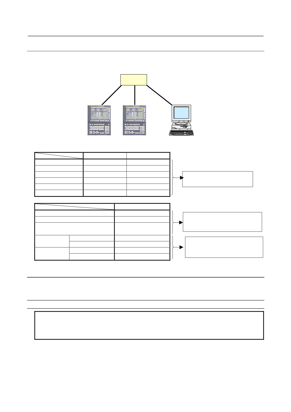
The following shows a setting example required for the FOCAS2/Ethernet function to operate.
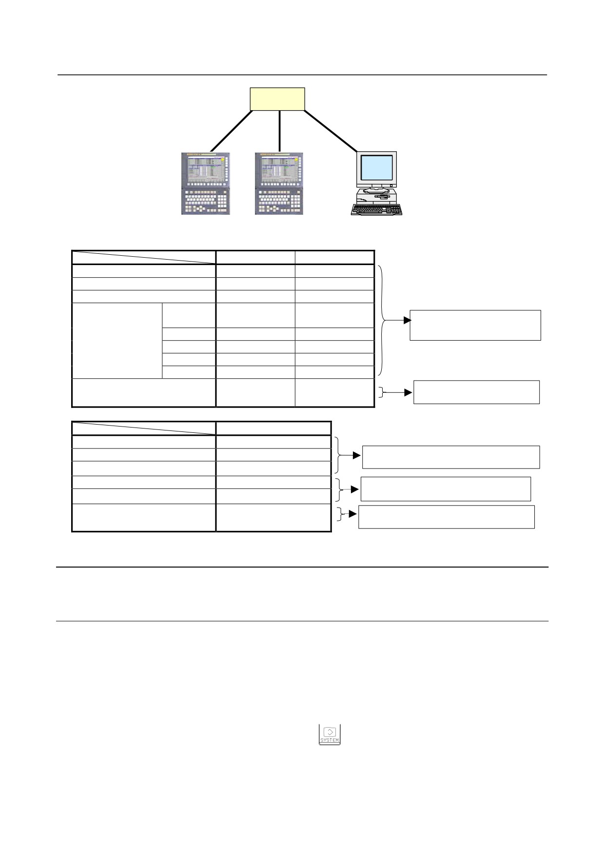
In this example, one personal computer is connected to two CNCs through FOCAS2/Ethernet.
HUB
10BASE-T or
100BASE-TX
CNC 1
CNC 2
PC 1
CNC 1
CNC 2
IP address
192.168.0.100
192.168.0.101
Subnet mask
255.255.255.0
255.255.255.0
Router IP address
None
None
The Ethernet parameter screen
TCP port number
8193
8193
is used for setting.
UDP port number
0
0
Time interval
0
0
PC 1
IP address
192.168.0.200
"Microsoft TCP/IP property" of the
Subnet mask
255.255.255.0
personal computer (Windows2000/ XP/
Default gateway
None
Vista) is used for setting.
CNC 1
NC IP address
192.168.0.100
The arguments of the data window
NC TCP port number
8193
library function cnc_allclibhndl3 are
CNC 2
NC IP address
192.168.0.101
used for setting.
NC TCP port number
8193
7.2.2
Setting of the FTP File Transfer Function
This section describes the settings required for the FTP file transfer function to operate using the
embedded Ethernet function.
Notes on using the FTP file transfer function for the first time
NOTE
1 When using the FTP file transfer function, use the embedded Ethernet port.
2 The number of FTP communications to which one CNC can be connected using
the FTP file transfer function is one.
- 440 -
B-64485EN/01
7.EMBEDDED ETHERNET FUNCTION
7.2.2.1 Operation on the FTP file transfer setting screen
On the Ethernet setting screen, set the parameters for operating the FTP file transfer function.
Procedure
1
Press the function key
2
Soft keys [EMBED PORT] appear.
(When there is no soft keys, press the continue key.)
3
By pressing the [EMBED PORT] soft key, the Ethernet Setting screen for the embedded Ethernet
port is displayed.
4
Press soft keys [COMMON] and [FTP TRANS] and then enter parameters for the items that appear.
NOTE
The parameters for the embedded Ethernet port and the parameters for the
PCMCIA Ethernet card are independent of each other.
If the [PCMCIA LAN] soft key is pressed, the PCMCIA Ethernet card can be set
up. However, the card setup is carried out for maintenance and is not necessary
usually.
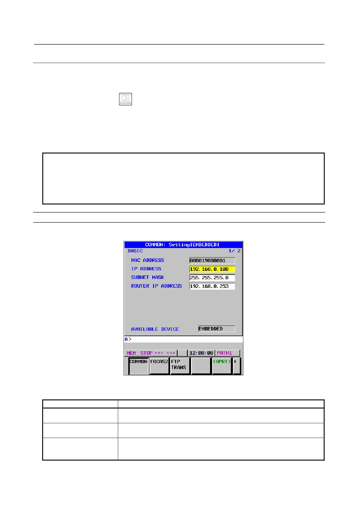
COMMON screen (BASIC)
Press soft key [COMMON]. The COMMON screen (BASIC) is displayed.
COMMON screen (BASIC)
Setting items
Item
Description
IP ADDRESS
Specify the IP address of the embedded Ethernet.
(Example of specification format: "192.168.0.100")
SUBNET MASK
Specify a mask address for the IP addresses of the network.
(Example of specification format: "255.255.255.0")
ROUTER IP ADDRESS
Specify the IP address of the router.
Specify this item when the network contains a router.
(Example of specification format: "192.168.0.253")
- 441 -
7.EMBEDDED ETHERNET FUNCTION
B-64485EN/01
Display items
Item
Description
MAC ADDRESS
Embedded Ethernet MAC address
AVAILABLE DEVICE
Enabled device of the embedded Ethernet.
Either the embedded Ethernet port or the PCMCIA Ethernet card is displayed.
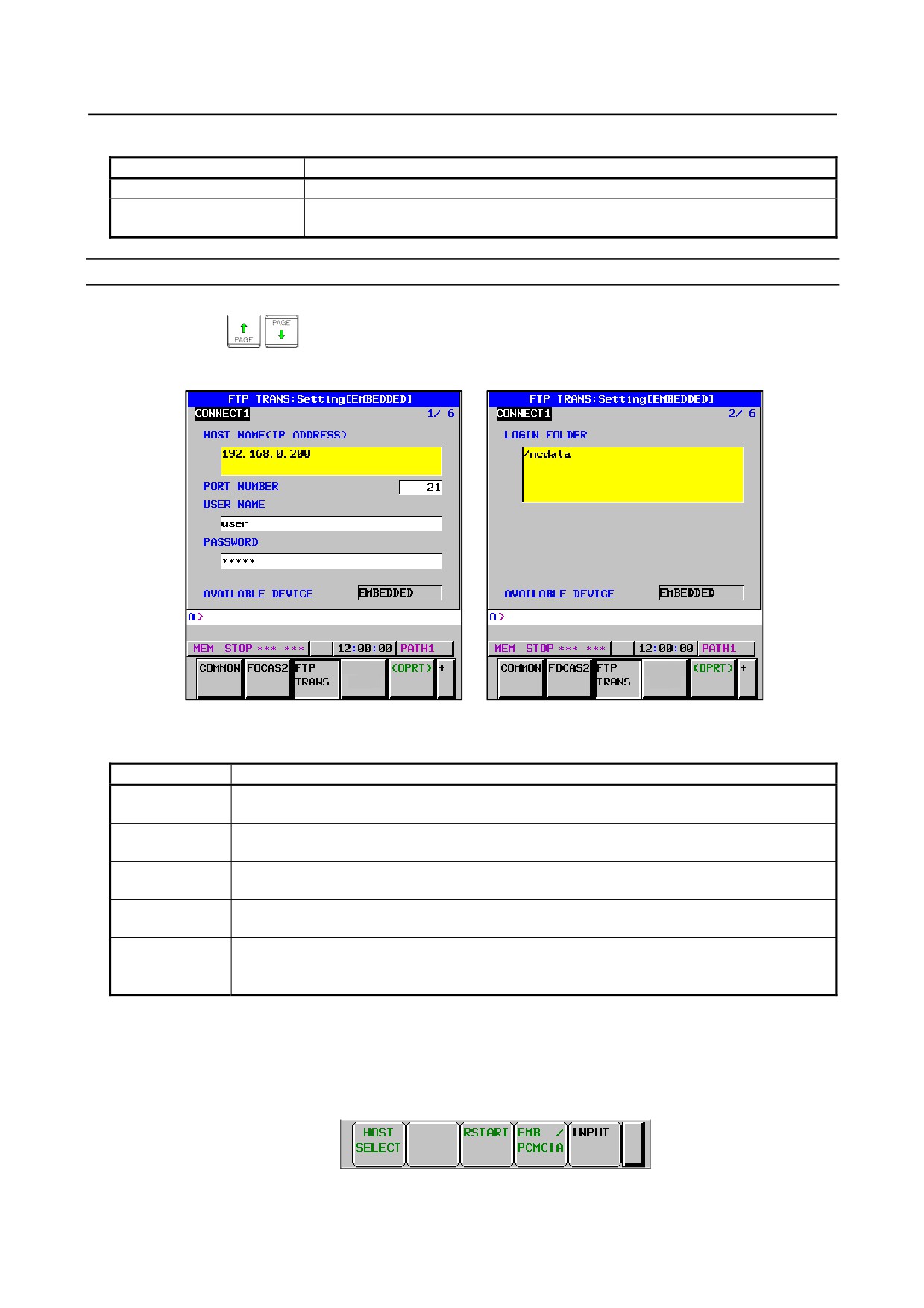
transfer screen (CONNECT1, CONNECT2, CONNECT3)
1
Press soft key [FTP TRANS]. The FTP transfer screen is displayed.
2
Page keys
can be used to make settings for the three host computers for connection
destinations 1 to 3.
FTP transfer screen (1st page)
FTP transfer screen (2nd page)
Setting items
Item
Description
HOST NAME
Specify the IP address of the host computer.
(Example of specification format: "192.168.0.200")
PORT NUMBER
Specify a port number to be used with the FTP file transfer function. An FTP session is used,
so that "21" is to be specified usually.
USERNAME
Specify a user name to be used for logging in to the host computer with FTP.
(Up to 31 characters can be specified.)
PASSWORD
Specify a password for the user name specified above. (Up to 31 characters can be specified.)
Be sure to set a password.
LOGIN FOLDER
Specify a work folder to be used when logging in to the host computer.
(Up to 127 characters can be specified.)
If nothing is specified, the home folder specified in the host computer becomes the log-in folder.
Operation
Select a destination.
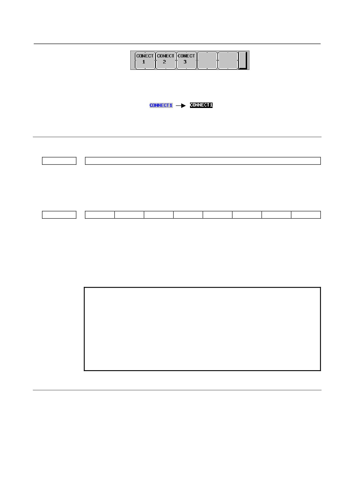
1
Pressing the [(OPRT)] soft key causes soft key [HOST SELECT] to be displayed. Pressing this soft
key causes soft keys [CONECT 1], [CONECT 2], and [CONECT 3] to be displayed.
- 442 -
B-64485EN/01
7.EMBEDDED ETHERNET FUNCTION
2
Depending on the host computer to be connected, press soft key [CONECT 1], [CONECT 2], or
[CONECT 3]. Destination 1, 2, or
3 is highlighted in the screen title field. The computer
corresponding to the highlighted destination is selected as the target computer to be connected.
When destination 1 is selected
7.2.2.2 Related NC parameters
The NC parameters related to the FTP file transfer function are described below.
0020
I/O CHANNEL : Input/output device selection, or interface number for a foreground input device
[Data type] Byte
[Valid data range] 9 : Select the embedded Ethernet as the input/output device.
For embedded Ethernet port
#7
#6
#5
#4
#3
#2
#1
#0
14880
PCH
[Input type] Parameter input
[Data type] Bit
#1 PCH When communication based on the FTP file transfer function starts, an FTP server
presence check based on PING is:
0: Made
1: Not made
NOTE
Usually, set this parameter to 0 (to make a check).
If this parameter is set to 1 (not to make an FTP server presence
check based on PING), several tens of seconds may be required
until an error is recognized when no FTP server is present on the
network.
Mainly for security, a personal computer may be set to ignore the
PING command. When communicating with such a personal
computer, set this parameter to 1 (not to make an FTP server
presence check based on PING).
7.2.2.3 Example of setting the FTP file transfer function
The following shows a setting example required for the FTP file transfer function to operate.
(The OS used on the PC in the example is Windows XP Professional.)
In this example, one personal computer is connected to two CNCs through the FTP file transfer function.
• On Personal Computer 1, the FTP server function operates.
• On CNC 1 and CNC 2, the FTP client operates as the FTP file transfer function.
- 443 -
7.EMBEDDED ETHERNET FUNCTION
B-64485EN/01
HUB
10BASE-T or
100BASE-TX
CNC 1
CNC 2
PC 1
CNC 1
CNC 2
IP address
192.168.0.100
192.168.0.101
Subnet mask
255.255.255.0
255.255.255.0
Router IP address
None
None
Connection host 1
Port
21
21
The Ethernet parameter screen
number
is used for setting.
IP address
192.168.0.200
192.168.0.200
User name
user
user
Password
user
user
Login DIR
None
None
NC parameter No. 20
9
9
The parameter screen is used
for setting.
PC 1
IP address
192.168.0.200
"Microsoft TCP/IP property" of the personal
Subnet mask
255.255.255.0
computer (WindowsXP) is used for setting.
Default gateway
None
User name
user
"User acount” of the personal computer
(WindowsXP) is used for setting.
Password
user
Login DIR
Default
"Internet service manager" of the personal
computer (WindowsXP) is used for setting.
7.2.3
Setting Up the DNS/DHCP Function
The DHCP/DNS function is set up by using the COMMON screen (DETAIL) and NC parameters.
7.2.3.1 Setting up DNS
This subsection describes the procedure for setting up a DNS.
Procedure
1
Enable the DNS client function, with reference to "Related NC Parameters," which will be seen
later.
2
Set up the DNS server of the host computer.
3
Connect the host computer on which the DNS server is working (hereafter referred to as a DNS
server), reboot the CNC, then press function key
4
Press soft keys [EMBED PORT] and [COMMON] in that order. The COMMON screen (DETAIL)
appears.
5
Enter the IP address of the DNS server in the corresponding DNS IP address field.
- 444 -
B-64485EN/01
7.EMBEDDED ETHERNET FUNCTION
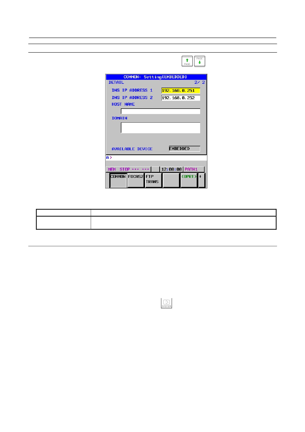
COMMON screen (DETAIL)
After pressing soft key [COMMON], press either page key
to call a desired COMMON
screen (DETAIL). Specify a DNS IP address.
COMMON screen (DETAIL)
Setting items
Item
Description
DNS IP ADDRESS 1, 2
Up to two DNS IP addresses can be specified.
The CNC searches for the DNS server using DNS IP addresses 1 and 2 in that order.
7.2.3.2 Setting up DHCP
This subsection describes the procedure for setting up a DHCP.
Procedure
1
Enable the DHCP client function, with reference to "Related NC Parameters," which will be seen
later.
2
Set up the DHCP server of the host computer.
3
Connect the host computer on which the DHCP server is working (hereafter referred to as a DHCP
server), reboot the CNC, then press function key
4
Press soft keys [EMBED PORT] and [COMMON] in that order. The COMMON screen appears.
5
If the DHCP client function of the CNC has been enabled and if the DHCP server is connected
successfully, the DHCP server automatically specifies the following items.
-
IP ADDRESS
-
SUBNET MASK
-
ROUTER IP ADDRESS
-
DNS IP ADDRESS
-
DOMAIN
If the DHCP server cannot be connected, "DHCP ERROR" is displayed in each field.
6
If the DNS client function has also been enabled and if the DHCP server and the DNS server work
together (if the DNS server supports dynamic DNS), enter a host name.
- 445 -
7.EMBEDDED ETHERNET FUNCTION
B-64485EN/01
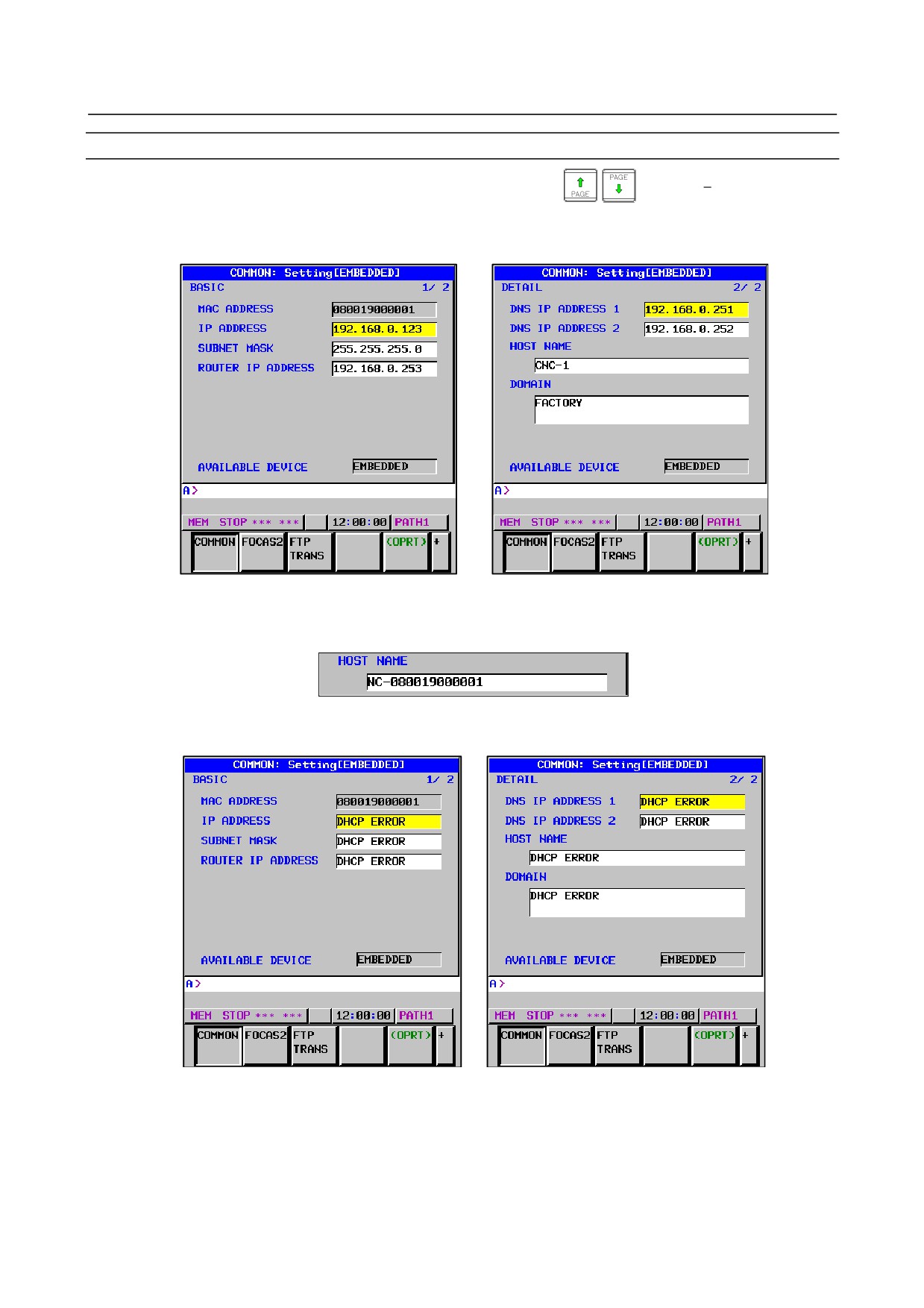
COMMON screen (BASIC and DETAIL)
After pressing soft key
[COMMON], press either page key
to call a desired Ethernet
common setting screens (BASIC and DETAIL).
If the DHCP server is connected successfully and if the setting data can be obtained, the screens are
displayed as shown below.
When the DHCP server is connected successfully
If the host name is not specified, the CNC automatically assigns a host name in the
"NC-<MAC-address>" format.
Example of automatically assigned host name
If the DHCP server cannot be connected, the screens are displayed as shown below.
When the DHCP server cannot be connected
- 446 -
B-64485EN/01
7.EMBEDDED ETHERNET FUNCTION
Check items
Item
Description
IP ADDRESS
If the DHCP server is connected successfully, the items obtained from
SUBNET MASK
the DHCP server are displayed.
ROUTER IP ADDRESS
If the DHCP server cannot be connected, "DHCP ERROR" is displayed.
DNS IP ADDRESS 1,2
DOMAIN
Setting items
Item
Description
HOST NAME
Enter the host name of the CNC.
If a DHCP server and a DNS server work together, the DHCP server notifies the
DNS server of this host name.
If the host name is left blank, a host name is automatically assigned in the
"NC-<MAC-address>" format.
Example of automatically assigned host name:
NC-080019000001
Display items
Item
Description
MAC ADDRESS
MAC address of embedded Ethernet
7.2.3.3 Related NC parameters
For embedded Ethernet port
#7
#6
#5
#4
#3
#2
#1
#0
14880
DHC
DNS
NOTE
Re-setting this parameter requires turning the power off and on again
or restarting the embedded Ethernet interface.
[Input type] Parameter input
[Data type] Bit
#5 DNS With the embedded Ethernet port, the DHCP function is:
0: Used.
1: Not used.
#6 DHC With the embedded Ethernet port, the DHCP function is:
0: Used.
1: Not used.
A change in these parameters becomes effective after the power is turned off and on or
after the embedded Ethernet function is restarted.
- 447 -
7.EMBEDDED ETHERNET FUNCTION
B-64485EN/01
7.2.4
Setting of the Unsolicited Messaging Function
This subsection describes the setting required to operate the unsolicited messaging function with the
embedded Ethernet function.
NOTE
To use the unsolicited messaging function with the embedded Ethernet port, the
enhanced embedded Ethernet function (-R952) is required.
7.2.4.1 Overview
This subsection provides an overview of the unsolicited messaging function and describes the execution
procedure.
Overview of the unsolicited messaging function
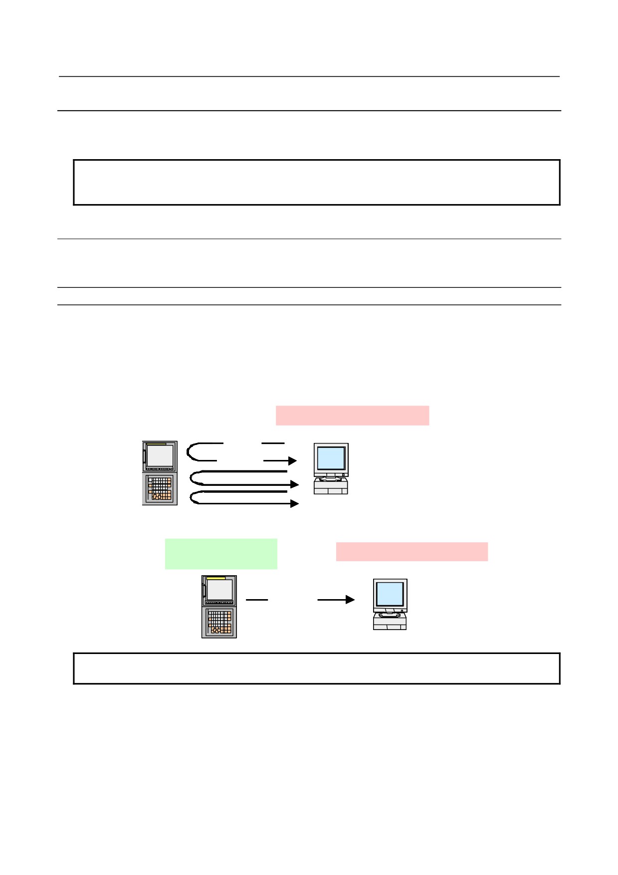
An overview of the unsolicited messaging function is provided below.
With the unsolicited messaging function, the CNC transmits messages (CNC/PMC data) in an unsolicited
manner to application software on the personal computer according to a command from an NC program
or ladder program. By using this function, the need for application processing on the personal computer to
periodically inquire about the state of the CNC can be eliminated.
When the conventional function is used
Application software
Inquiry
Response
Application checks for
CNC/PMC data changes.
When the unsolicited messaging function is used
NC program or ladder
Application software
program
NC program or ladder
program checks for
Application receives
Notification
CNC/PMC data
notification from CNC.
changes.
NOTE
The unsolicited messaging function is a part of the FOCAS2/Ethernet function.
- 448 -

B-64485EN/01
7.EMBEDDED ETHERNET FUNCTION
Unsolicited messaging function execution procedure
The execution procedure for the unsolicited messaging function is described below.
1
Preparation on the personal compute
Create an application using the FOCAS2 function for the unsolicited messaging function and install
the unsolicited message server on a personal computer. For the method of creating an application
using the FOCAS2 function for the unsolicited messaging function and the method of installing the
unsolicited message server, refer to Chapter
5, "Unsolicited Messaging Function", in the
“Data
Window Library Specifications" supplied with the FOCAS1/2 library.
2
Preparation on the CNC
Create an NC program or ladder program for controlling unsolicited messaging.
For the method of creating an NC program or ladder program, see Subsection 7.2.4.6, "Execution
methods".
3
Setting of the communication parameters for the unsolicited messaging function
To use the unsolicited messaging function, the following communication parameter settings are
needed:
(1) Setting for using the FOCAS2/Ethernet function
(2) Setting of the parameters for the unsolicited messaging function
For (2), a choice can be made from two modes of setting: CNC mode for setting on the CNC screen
and the PC mode for setting on the personal computer.
For the setting method of (1) and (2), see Subsection 7.2.4.2, "Setting of the FOCAS2/Ethernet
function" through Subsection 7.2.4.5, "Setting on the personal computer".
4
Starting the NC program or ladder program
Start the NC program or ladder program created in step 2, "Preparation on the CNC". At this time,
no unsolicited message is transmitted to the personal computer until step 5, "Starting the unsolicited
messaging function", is executed.
5
Starting the unsolicited messaging function
Execute the FOCAS2 function cnc_unsolicstart on the personal computer. This execution places the
CNC in the state (named "Ready") where a transmission request from the NC program or ladder
program is awaited. Each time a transmission request is made from the NC program or ladder
program, an unsolicited message is automatically transmitted to the personal computer.
6
Ending the unsolicited messaging function
To end unsolicited message transmission, execute the FOCAS2 function cnc_unsolicstop on the
personal computer. This execution places the CNC in the state (named "Not Ready") where no
unsolicited message is transmitted even when a request for transmission is made from the NC
program or ladder program.
7.2.4.2 Setting of the FOCAS2/Ethernet function
This subsection describes the setting of the FOCAS2/Ethernet function for operating the unsolicited
messaging function.
Procedure
1
Enable the unsolicited messaging function according to "Related NC parameters" described later.
2
Start the CNC again then press function key
3
Soft key [EMBED PORT] is displayed. (Press the continuous menu key until the soft key is
displayed.)
4
Press soft key [EMBED PORT]. The Ethernet Setting screen for the embedded Ethernet port is
displayed.
5
Press soft keys [COMMON] and [FOCAS2] then make settings on each screen.
6
Press soft key [UNSOLI MSG]. The Unsolicited Message screen is displayed. (Press the continuous
menu key until the soft key [UNSOLI MSG] is displayed.) For details of the Unsolicited Message
screen, see Subsections starting with Subsection 7.2.4.3, "Mode selection".
- 449 -
7.EMBEDDED ETHERNET FUNCTION
B-64485EN/01
COMMON screen (BASIC)
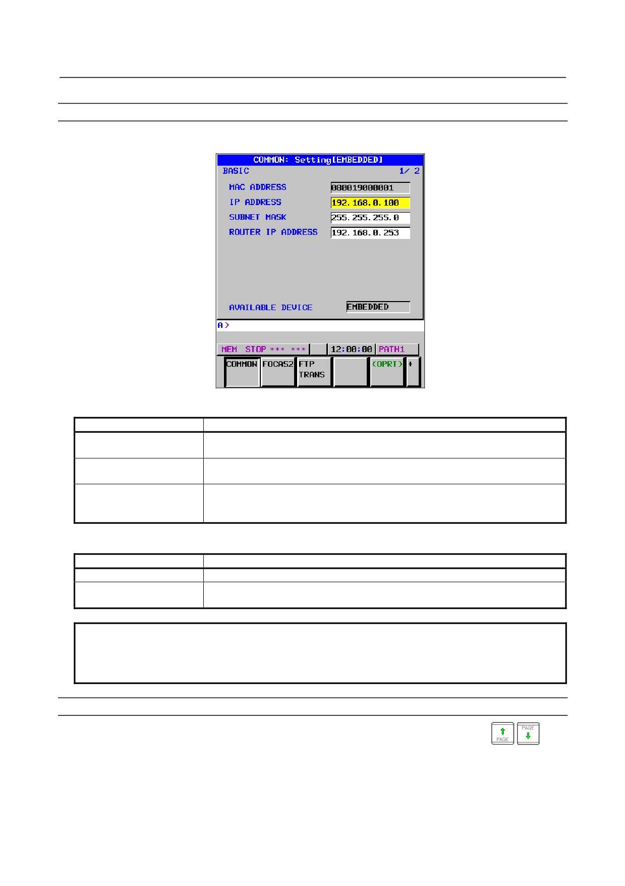
Press soft key [COMMON]. The COMMON screen (BASIC) is displayed.
COMMON screen (BASIC)
Setting items
Item
Description
IP ADDRESS
Specify the IP address of the embedded Ethernet.
(Example of specification format: "192.168.0.100")
SUBNET MASK
Specify a mask address for the IP addresses of the network.
(Example of specification format: "255.255.255.0")
ROUTER IP ADDRESS
Specify the IP address of the router.
Specify this item when the network contains a router.
(Example of specification format: "192.168.0.253")
Display items
Item
Description
MAC ADDRESS
Embedded Ethernet MAC address
AVAILABLE DEVICE
Enabled device of the embedded Ethernet.
Either the embedded Ethernet port or the PCMCIA Ethernet card is displayed.
NOTE
Set page 2 (DETAIL screen) of the COMMON screen when using the
DNS/DHCP function. For details, see Subsection 7.2.3, "Setting Up the
DNS/DHCP Function".
COMMON screen (DETAIL)
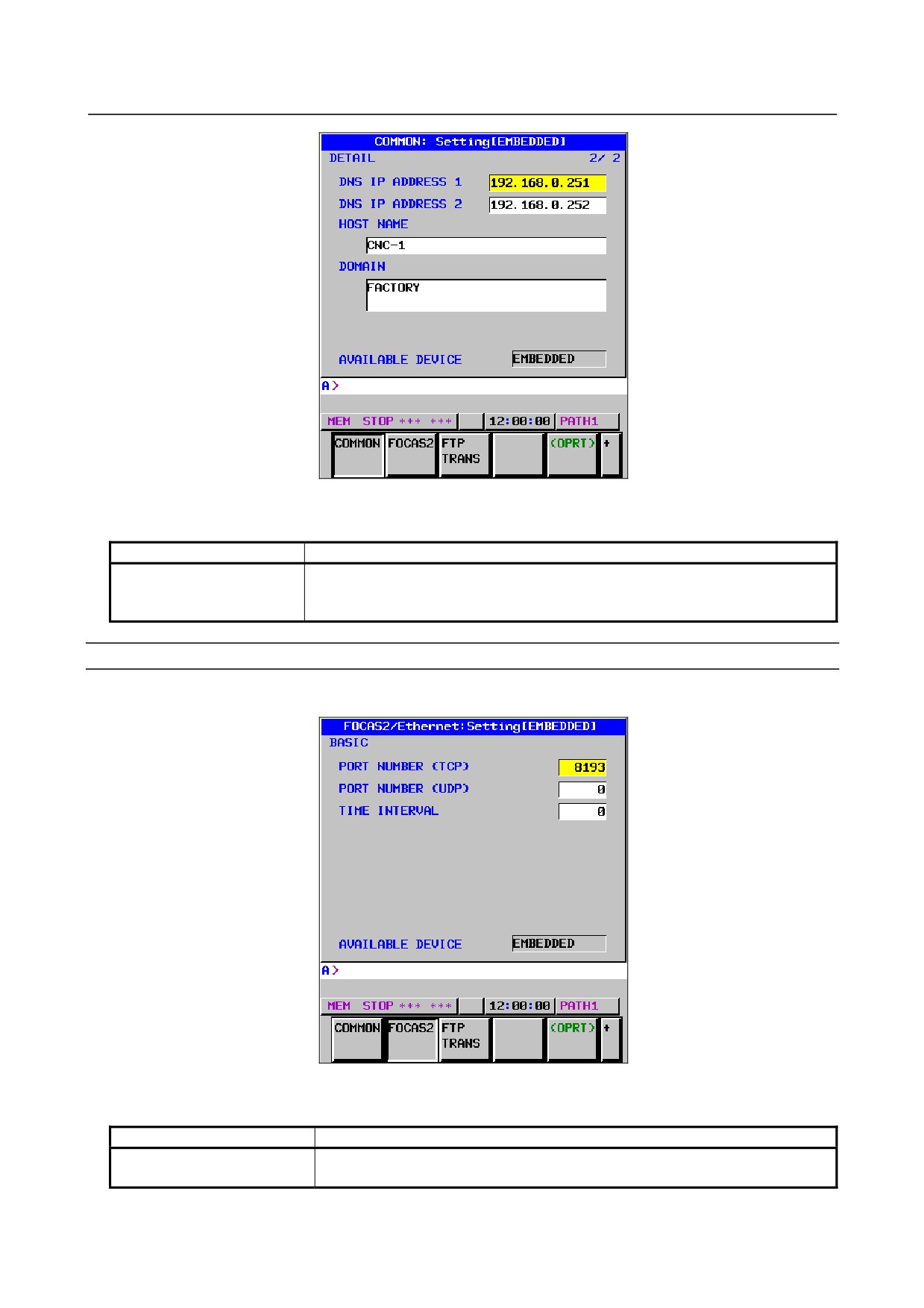
When using the DNS client function, press soft key [COMMON] then press page key
. The
COMMON screen (DETAIL) is displayed. Set the DNS IP address setting items.
- 450 -
B-64485EN/01
7.EMBEDDED ETHERNET FUNCTION
COMMON screen (DETAIL)
Setting items
Item
Description
DNS IP ADDRESS 1, 2
Up to two DNS IP addresses can be specified.
The CNC searches for the DNS server using DNS IP addresses 1 and 2 in that
order.
FOCAS2 screen
Press soft key [FOCAS2]. The FOCAS2 screen is displayed.
FOCAS2 screen
Setting items
Item
Description
PORT NUMBER (TCP)
Specify a port number to be used with the unsolicited messaging function
(FOCAS2/Ethernet function). The valid input range is 5001 to 65535.
- 451 -
7.EMBEDDED ETHERNET FUNCTION
B-64485EN/01
Item
Description
PORT NUMBER (UDP)
Set this item to 0 when it is used as the unsolicited messaging function
(FOCAS2/Ethernet function).
TIME INTERVAL
Set this item to 0 when it is used as the unsolicited messaging function
(FOCAS2/Ethernet function).
7.2.4.3 Mode selection
This subsection describes the selection of a mode for setting the unsolicited messaging function.
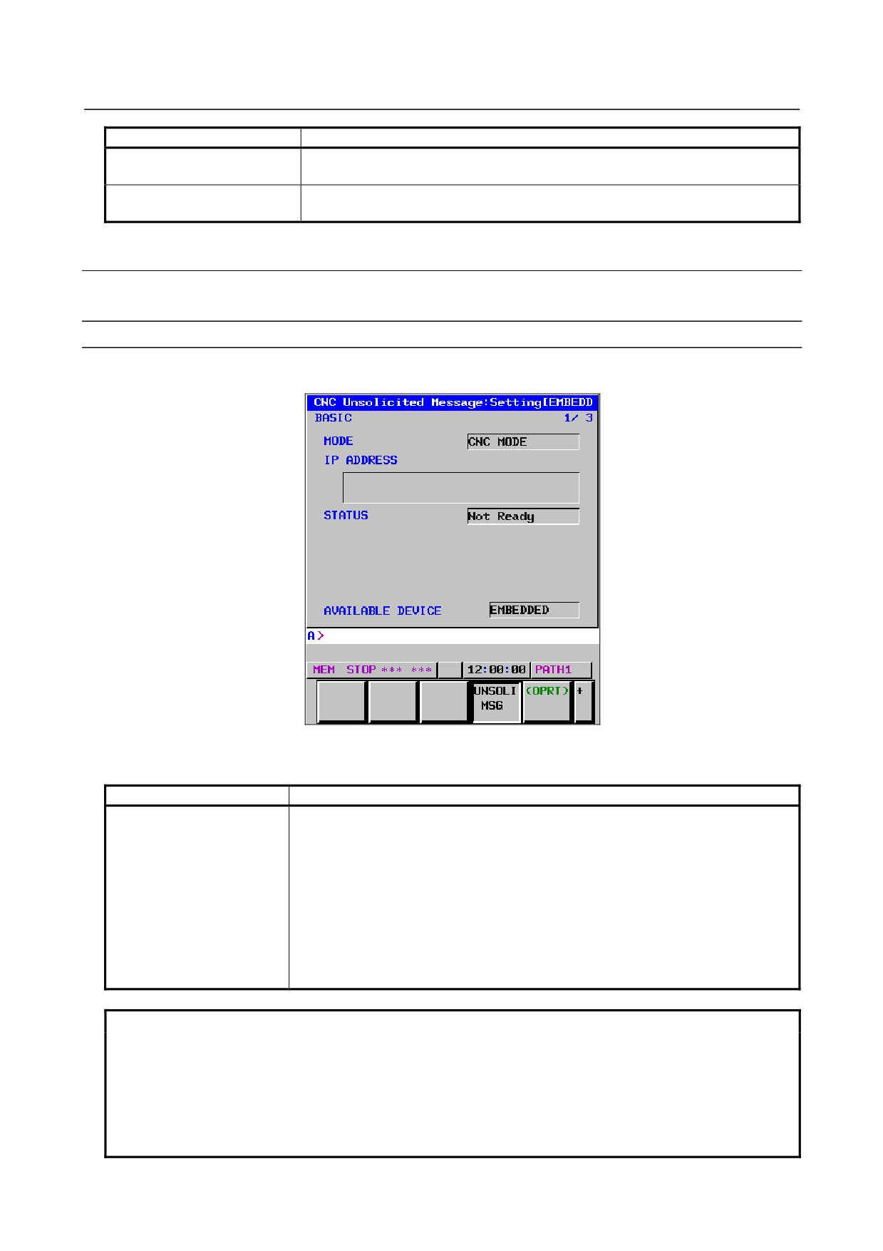
Unsolicited Message screen (BASIC)
Press soft key [UNSOLI MSG]. The Unsolicited Message screen (BASIC) is displayed.
Unsolicited Message screen 1 (BASIC)
Setting items
Item
Description
MODE
Select a mode for setting the unsolicited messaging function.
For the method of selection, see "Operation" described later.
• When "CNC MODE" is selected
This mode enables setting on the CNC screen.
In this case, setting on the personal computer is disabled.
For details, see Subsection 7.2.4.4, "Setting on the CNC screen".
• When "PC MODE" is selected
This mode enables setting on the personal computer.
In this case, setting on the CNC screen is disabled.
For details, see Subsection 7.2.4.5, "Setting on the personal computer".
NOTE
1 The mode is set to "PC MODE" at the time of initial use.
2 The mode can be switched only in the "Not Ready" state. For the "Not Ready"
state, see "Display items" provided later.
3 If the mode is switched from "CNC MODE" to "PC MODE", all parameters set on
the CNC screen are cleared.
4 The mode can be switched on the available device side only.
- 452 -
B-64485EN/01
7.EMBEDDED ETHERNET FUNCTION
Operation
The mode can be switched as described below.
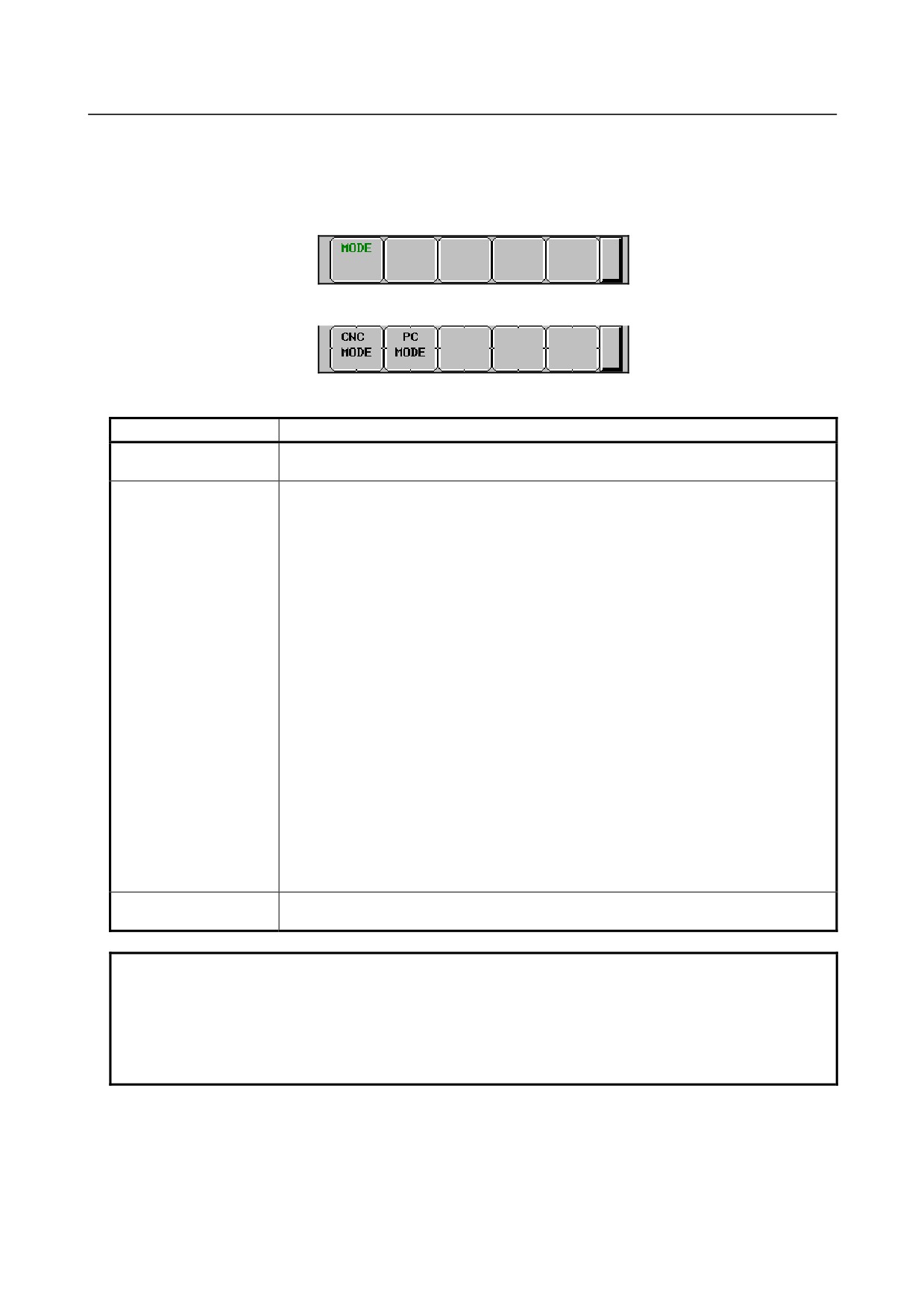
1
Press soft key [(OPRT)]. Soft key [MODE] is displayed.
2
Press soft key [MODE]. Soft keys [CNC MODE] and [PC MODE] are displayed.
Display items
Item
Description
IP ADDRESS
Displays the IP address of the personal computer currently connected.
(Example of display format: "192.168.0.1")
STATUS
Displays the current state.
The following five states are available:
<1> Not Ready
State where data is not transmitted even when a request for data transmission is
made from an NC program or ladder program
<2> Ready
State where data is transmitted when a request for data transmission is made from
an NC program or ladder program
<3> Sending...
State present from the acceptance of a request for data transmission from an NC
program or ladder program until data transmission is completed
<4> Receiving...
State present from completion of data transmission until response data is received
<5> Completed
State present from reception of response data until response data processing is
completed
[Supplement]
• Data transmission
Means unsolicited message transmission (CNC→PC).
• Response data
Means a response to an unsolicited message (PC→CNC).
AVAILABLE DEVICE
Device where embedded Ethernet is currently enabled.
The embedded Ethernet port or PCMCIA Ethernet card is displayed.
NOTE
1 To switch the state from "Not Ready" to "Ready”, the FOCAS2 function
cnc_unsolicstart needs to be executed on the personal computer.
2 To switch the state from other than "Not Ready" to “Not Ready”, the FOCAS2
function cnc_unsolicstop needs to be executed on the personal computer.
3 For the timing charts of the states, see Subsection 7.2.4.6, "Execution methods".
- 453 -
7.EMBEDDED ETHERNET FUNCTION
B-64485EN/01
7.2.4.4 Setting on the CNC screen
This subsection describes the method of setting on the Unsolicited Message screen.
NOTE
1 To enable the settings on the CNC screen and perform unsolicited messaging,
the procedure below needs to be used.
(1) Set all setting items on the Unsolicited Message screen (CONNECT).
(2) Press soft key [(OPRT)] then press soft key [APPLY].
(3) Start unsolicited messaging (execute the FOCAS2 function
cnc_unsolicstart) on the personal computer.
2 Setting of the setting items on the Unsolicited Message screen (CONNECT) and
execution of the soft keys ([(OPRT)] then [APPLY]) are possible only in the "Not
Ready" state. For the "Not Ready" state, see "Display items" in Subsection
7.2.4.3, "Mode selection".
3 On the setting screen on the unavailable device side, the setting items can be
set. However, execution of the soft keys ([(OPRT)] then [APPLY]) is possible on
the available device side only.
Unsolicited Message screen (CONNECT)
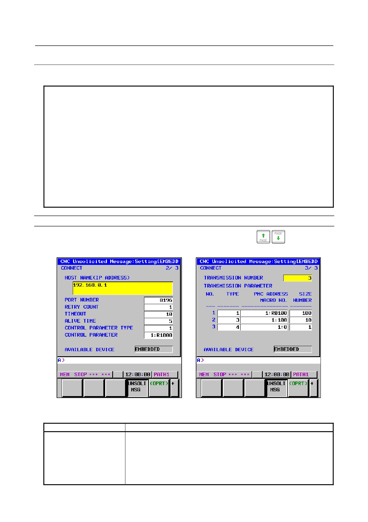
Press soft key [UNSOLI MSG] then open page 2 and page 3 with page keys
. The Unsolicited
Message screen (CONNECT) is displayed.
Unsolicited Message screen 2 (CONNECT)
Unsolicited Message screen 3 (CONNECT)
Setting items
Item
Description
HOST NAME (IP ADDRESS)
When the DNS client function is disabled, specify the IP address of the
communication destination personal computer.
(Example of specification format: "192.168.0.1")
When the DNS client function is enabled, specify the host name of the
communication destination personal computer. (Up to 63 characters can be
specified.)
(Example of specification format: "UNSOLI-SRV.FACTORY")
- 454 -

B-64485EN/01
7.EMBEDDED ETHERNET FUNCTION
Item
Description
PORT NUMBER
Specify the TCP port number and UDP port number of the communication
destination personal computer.
Usually, specify "8196".
The valid input range is 5001 to 65535.
RETRY COUNT
Specify the number of retries to be made when there is no response to data
transmitted by the communication function.
The valid input range is 0 to 32767.
TIMEOUT
Specify a time-out period (in sec) from the transmission of data by the
communication function until a response is made to the transmitted data.
The valid input range is 1 to 32767.
ALIVE TIME
Specify the time interval (in sec) of the alive signal to be transmitted while the
communication function is operating normally.
Specify a value not greater than the value of TIMEOUT.
The valid input range is 1 to 32767.
CONTROL PARAMETER
Specify a type of control parameter. When this parameter is set to 0, the control
TYPE
parameter is invalid.
• When set to 1: PMC address (response notification method)
• When set to 2: PMC address (simplified method)
• When set to 3: Custom macro variable (simplified method)
• When set to 4: Volatile RTM variable (simplified method)
(Note) The RTM variable is a real-time custom macro variable.
CONTROL PARAMETER
Specify a control parameter for executing data transmission.
When CONTROL PARAMETER TYPE is set to 1
Specify a PMC address for control.
A PMC address in the R area or E area may be specified.
Two bytes starting at a specified address are allocated in the area.
When CONTROL PARAMETER TYPE is set to 2
Specify a PMC address for control.
A PMC address in the R area or E area may be specified.
Only a specified address (one byte) is allocated in the area.
When CONTROL PARAMETER TYPE is set to 3
Specify a custom macro variable number for control.
Only a volatile common variable may be specified as a custom macro variable.
Only the variable with a specified variable number is allocated in the area.
When CONTROL PARAMETER TYPE is set to 4
Specify a RTM variable number for control.
Only a volatile RTM variable may be specified as a RTM variable.
Only the variable with a specified variable number is allocated in the area.
TRANSMISSION NUMBER
Specify the number of data items to be transmitted.
The valid input range is 1 to 3.
TRANSMISSION
Specify each parameter for transmission data.
PARAMETER
(NO.1 to 3)
TYPE
Specify a transmission data type. When this parameter is set to 0, the
transmission parameter is invalid.
• When set to 1 or 2: PMC address
• When set to 3: Custom macro variable
• When set to 4: Volatile RTM variable
• When set to 5: Nonvolatile RTM variable
PMC ADDRESS or
Specify the start of a transmission data area
MACRO NO.
When TYPE is set to 1 or 2
Specify a PMC address for transmission.
When TYPE is set to 3
Specify a custom macro variable number for transmission.
When TYPE is set to 4 or 5
Specify a RTM variable number for transmission.
- 455 -
7.EMBEDDED ETHERNET FUNCTION
B-64485EN/01
Item
Description
SIZE or NUMBER
Specify the size of a transmission data area or the number of variables.
The maximum specifiable number of bytes is as follows:
• When TRANSMISSION NUMBER is set to 1: 2890 bytes
• When TRANSMISSION NUMBER is set to 2: 2874 bytes in total
• When TRANSMISSION NUMBER is set to 3: 2858 bytes in total
When using macro variables (custom macro variables or RTM variables), use a
conversion rate of one variable for eight bytes.
When TYPE is set to 1 or 2
Specify a PMC area size (bytes) for transmission.
When TYPE is set to 3
Specify the number of custom macro variables for transmission.
When a macro variable number of 1000 or greater (system variable) is used,
this parameter can be set to 1 only.
When TYPE is set to 4 or 5
Specify the number of RTM variables for transmission.
CAUTION
1
When setting a PMC address for control or a PMC address for transmission,
observe the following:
(1) When a multi-path PMC is used, use the following input format:
<path-number>:<PMC-address>
When specifying the PMC address R0500 of the second PMC path, for
example, input "2:R500". When only the PMC address (R500) is input, the
specification of the first path (1:R0500) is assumed for processing.
When the key for ":" is unavailable, use the key for "/" or "EOB" instead.
(2) Ensure that a PMC address area for control never overlaps PMC areas used
by other functions (FL-net, PROFIBUS-DP, DeviceNet, and CC-Link).
2
When setting a macro variable for control or a macro variable for transmission,
observe the following:
(1) When a multi-path CNC is used, use the following input format:
<path-number>:<variable-number>
When specifying variable number #100 of the second CNC path, for
example, input "2:100". When only the variable number (100) is input, the
specification of the first path (1:100) is assumed for processing.
When the key for ":" is unavailable, use the key for "/" or "EOB" instead.
(2) Ensure that a macro variable for control never be doubly specified as a
variable to be used for a purpose other than the unsolicited messaging
function.
NOTE
1 Two methods are available for PMC address specification in CONTROL
PARAMETER TYPE: response notification method and simplified method. For
details of the methods, see Subsection 7.2.4.6, "Execution methods".
2 The valid setting range of PMC addresses depends on the usable PMC memory
type. For details, refer to "PMC Programming Manual (B-64513EN)".
3 The valid setting ranges of custom macro variable numbers and RTM variable
numbers depend on the selected options. For details, refer to "Operator’s
Manual (Common to Lathe System/Machining Center System) (B-64484EN)".
- 456 -
B-64485EN/01
7.EMBEDDED ETHERNET FUNCTION
NOTE
4 Ensure that the setting of TRANSMISSION NUMBER matches the settings of
TRANSMISSION PARAMETER (NO. 1 to NO. 3). If TRANSMISSION NUMBER
is set to 3, and an invalid value is specified in any of TRANSMISSION
PARAMETER NO. 1 to NO. 3, for example, execution of soft key [APPLY]
results in an error.
Operation
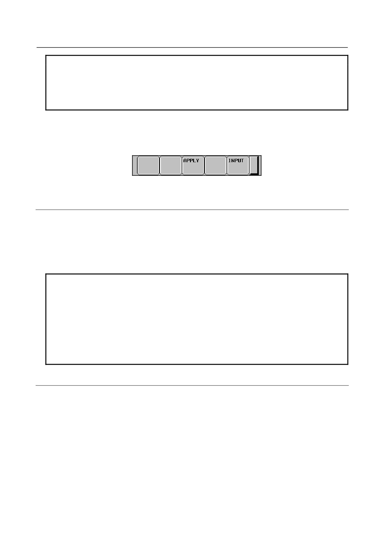
The settings of all setting items on the Unsolicited Message screen (CONNECT) can be made effective as
follows:
1
Press soft key [(OPRT)]. Soft key [APPLY] is displayed.
2
Press soft key [APPLY].
7.2.4.5 Setting on the personal computer
For setting on the personal computer, create and set an application by using the following FOCAS2
functions:
• cnc_wrunsolicprm2 Parameter setting 2 for unsolicited messaging
• cnc_unsolicstart
Start of unsolicited messaging
For details, refer to Chapter
5, "Unsolicited Messaging Function", in the
“Data Window Library
Specifications" supplied with the FOCAS1/2 library.
NOTE
1 To start unsolicited messaging, the FOCAS2 function cnc_wrunsolicprm2 needs
to be executed first then the FOCAS2 function cnc_unsolicstart needs to be
executed.
2 The FOCAS2 function cnc_wrunsolicprm2 can be executed only in the "Not
Ready" state. For details of the state, see "Display items" in Subsection 7.2.4.3,
"Mode selection".
3 When the FOCAS2 function cnc_wrunsolicprm2 is executed, the Unsolicited
Message screen (CONNECT) displays the settings made on the personal
computer.
7.2.4.6 Execution methods
How to execute the unsolicited messaging function is described below.
To execute the unsolicited messaging function, three methods are available:
• Using a PMC address for control based on the response notification method in a ladder program
• Using a PMC address for control based on the simplified method in a ladder program
• Using a macro variable for control based on the simplified method in an NC program
- 457 -

7.EMBEDDED ETHERNET FUNCTION
B-64485EN/01
NOTE
1 When a ladder program is used, the response notification method and the
simplified method are available. A major difference is that the response
notification method sends RES_CODE to the ladder program in response to data
transmission but the simplified method does not send a response.
To utilize a ladder program based on logic used with the Series 16i, for example,
use the response notification method. When RES_CODE is unnecessary or a
new ladder program is created, the simplified method can be used.
2 RES_CODE is recorded on the Ethernet log screen when a value other than
0x00 and 0x01 is detected.
3 For details of RES_CODE, refer to Chapter 5, "Unsolicited Messaging Function", in the
“Data Window Library Specifications" supplied with the FOCAS1/2 library.
When a PMC address for control is used (response notification method)
A description of using a PMC address for control in a ladder program according to the response
notification method is provided below.
NOTE
A combination of a PMC address for control and a macro variable for
transmission is also usable. In this case, note that the read timing of the value of
a macro variable to be transmitted cannot be identified when viewed from the
ladder program.
In the description below, a PMC address is used for both of control and
transmission.
Explanation of PMC address signals for control
A detailed description of PMC address signals for control used to execute the unsolicited messaging
function is provided below. A PMC address area for control consists of 2 bytes.
The description below assumes that Rxxxx (with no PMC path number specified) is used as a PMC
address for control.
No.
#7
#6
#5
#4
#3
#2
#1
#0
Rxxxx
REQ
REQ <Rxxxx.7>
[Name] Message transmission request signal
[Classification] Input signal
[Function] Requests transmission of an unsolicited message.
[Operation] After preparing a transmission message at a PMC address for transmission, the ladder
program sets this signal to 1. The message is then transmitted to the personal computer.
No.
#7
#6
#5
#4
#3
#2
#1
#0
Rxxxx+1
RES
COM
RES_CODE
RES <Rxxxx+1.7>
[Name] Message response reception signal
[Classification] Output signal
[Function] Posts the reception of a response to an unsolicited message.
- 458 -
B-64485EN/01
7.EMBEDDED ETHERNET FUNCTION
[Output condition] Upon reception of a message by the personal computer, a response to the message is
transmitted to the CNC (communication function). When the CNC (communication
function) receives the response, this signal is set to 1. When this signal is set to 1, the
ladder program reads RES_CODE then clears REQ to 0. Next, the CNC (communication
function) clears RES_CODE to 0 then sets this signal to 0.
COM <Rxxxx+1.6>
[Name] Message transmission start signal
[Classification] Output signal
[Function] Posts the start of transmission of an unsolicited message.
[Output condition] When transmission of a message to the personal computer is started, this signal is set to 1.
Upon completion of message transmission, this signal is set to 0.
RES_CODE <Rxxxx+1.0> to <Rxxxx+1.5>
[Name] Message response reception result signal
[Classification] Output signal
[Function] Posts the reception result of a response to an unsolicited message.
[Output condition] The reception result of a response to a message is set. After reading this signal, the ladder
program clears REQ to 0. The CNC (communication function) then clears this signal to 0.
NOTE
For details of RES_CODE, refer to Chapter 5, "Unsolicited Messaging Function", in the
“Data Window Library Specifications" supplied with the FOCAS1/2 library.
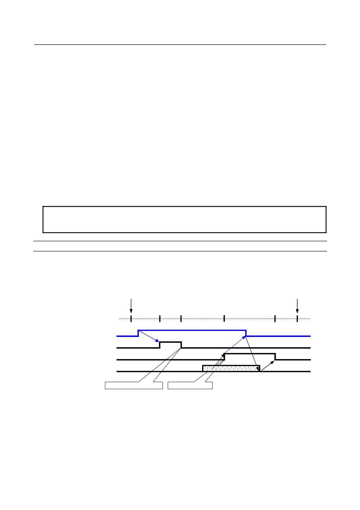
Timing chart of PMC address signals for control
The timing chart of PMC address signals for control based on the response notification method is
described below.
In the example below, an unsolicited message is transmitted once after reception of the FOCAS2 function
cnc_unsolicstart then the FOCAS2 function cnc_unsolicstop is received.
FOCAS2 function cnc_unsolicstart
FOCAS2 function cnc_unsolicstop
Not Ready Ready Sending... Receiving...
Completed
Ready Not Ready
State
REQ (ladder program →
(1)
communication function)
(2)
(3)
(5)
(6)
COM (communication function
→ ladder program)
RES (communication function
(4)
→ ladder program)
(7)
RES_CODE (communication
function → ladder program)
Transmission completed
Receive data valid
(1) After checking that RES is set to 0, the ladder program prepares a message then sets REQ to 1.
(2) Because of REQ set to 1, the communication function sets COM to 1 then transmits the message.
(3) Upon completion of message transmission, the communication function sets COM to 0.
(4) Upon reception of a response to the message, the communication function sets RES_CODE then sets
RES to 1.
(5) Because of RES set to 1, the ladder program reads RES_CODE then sets REQ to 0.
(6) Because of REQ set to 0, the communication function clears RES_CODE to 0.
(7) The communication function sets RES to 0.
- 459 -
7.EMBEDDED ETHERNET FUNCTION
B-64485EN/01
NOTE
For details of the states, see "Display items" in Subsection 7.2.4.3, "Mode
selection".
When a PMC address for control is used (simplified method)
A description of using a PMC address for control in a ladder program according to the simplified method
is provided below.
NOTE
A combination of a PMC address for control and a macro variable for
transmission is also usable. In this case, note that the read timing of the value of
a macro variable to be transmitted cannot be identified when viewed from the
ladder program.
In the description below, a PMC address is used for both of control and
transmission.
Explanation of PMC address signals for control
A detailed description of PMC address signals for control used to execute the unsolicited messaging
function is provided below. A PMC address area for control consists of 1 byte.
The description below assumes that Rxxxx (with no PMC path number specified) is used as a PMC
address for control.
No.
#7
#6
#5
#4
#3
#2
#1
#0
Rxxxx
REQ
REQ <Rxxxx#7>
[Name] Message transmission request signal
[Classification] Input/Output signal
[Function] Requests transmission of an unsolicited message.
[Operation] After preparing a transmission message at a PMC address for transmission, the ladder
program sets this signal to 1. The message is then transmitted to the personal computer.
Upon reception of a response to the message, the CNC (communication function) clears
this signal to 0.
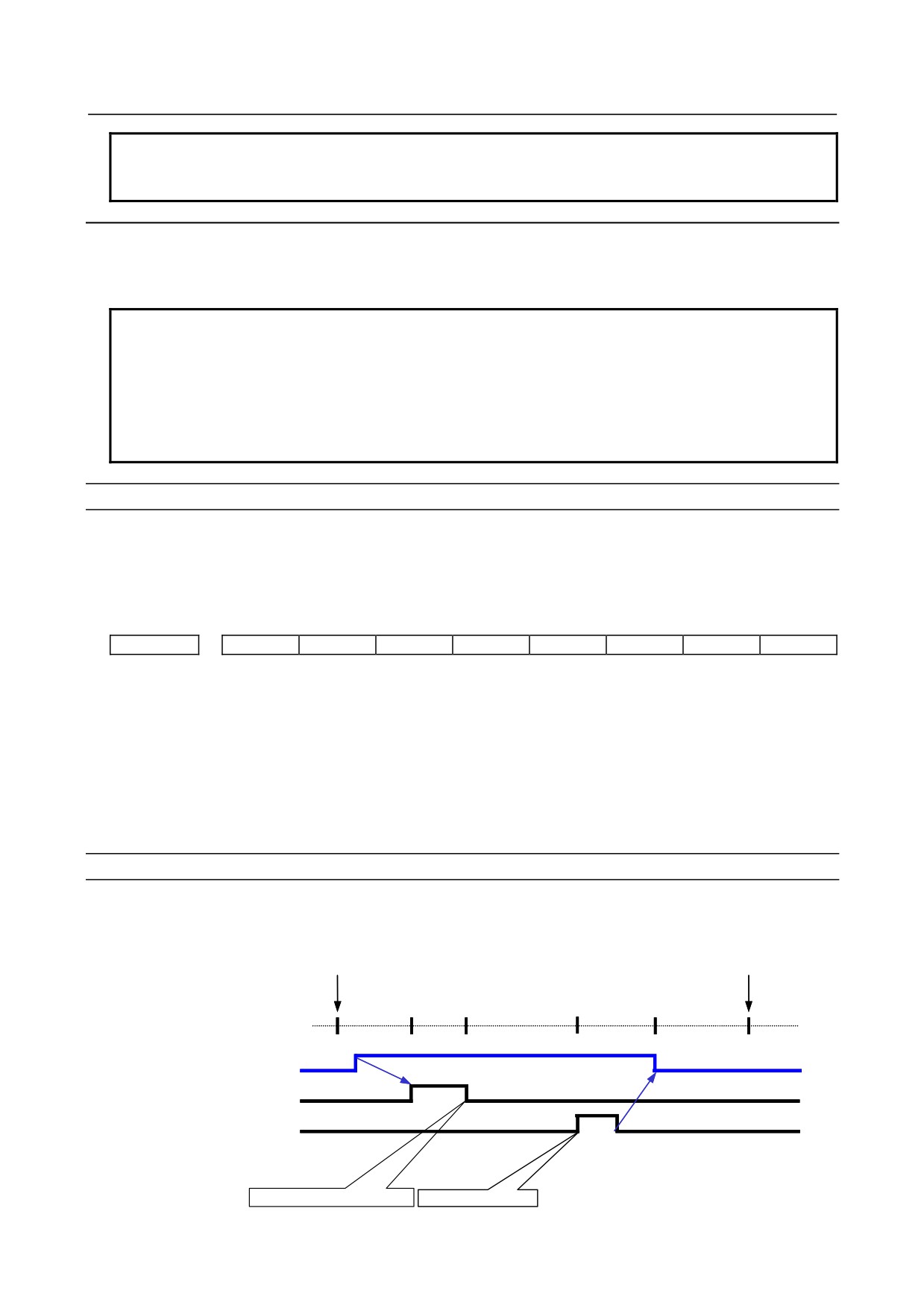
Timing chart of PMC address signals for control
The timing chart of PMC address signals for control based on the simplified method is described below.
In the example below, an unsolicited message is transmitted once after reception of the FOCAS2 function
cnc_unsolicstart then the FOCAS2 function cnc_unsolicstop is received.
FOCAS2 function cnc_unsolicstart
FOCAS2 function cnc_unsolicstop
Not Ready Ready Sending... Receiving... Completed
Ready
Not Ready
State
REQ (ladder program ↔
(1)
communication function)
(2)
(5)
(3)
Transmission processing by
communication function
(4)
Reception processing by
communication function
Transmission completed
Response received
- 460 -

B-64485EN/01
7.EMBEDDED ETHERNET FUNCTION
(1) After checking that REQ is set to 0, the ladder program prepares a message then sets REQ to 1.
(2) Because of REQ set to 1, the communication function transmits the message.
(3) The communication function completes message transmission processing.
(4) Upon reception of a response to the message, the communication function completes reception
processing.
(5) Because of reception processing completed, the communication function sets REQ to 0.
NOTE
For details of the states, see "Display items" in Subsection 7.2.4.3, "Mode
selection".
When a macro variable for control is used (simplified method)
A description of using a macro variable for control in an NC program according to the simplified method
is provided below.
Macro variables for control are classified as custom macros and RTM macros, but the same execution
method is applicable.
NOTE
A combination of a macro variable for control and a PMC address for
transmission is also usable. In this case, note that the read timing of the value of
PMC data to be transmitted cannot be identified when viewed from the NC
program.
In the description below, a macro variable is used for both of control and
transmission.
Explanation of a macro variable for control
A detailed description of a macro variable for control used to execute the unsolicited messaging function
is provided below. One macro variable for control is used.
The description below assumes that #xxxx (with no CNC path number specified) is used as a macro
variable number for control.
REQ <#xxxx>
[Name] Message transmission request signal
[Classification] Input/Output signal
[Function] Requests transmission of an unsolicited message.
[Operation] After preparing a transmission message in a macro variable for transmission, the NC
program sets this signal to 1. The message is then transmitted to the personal computer.
Upon reception of a response to the message, the CNC (communication function) clears
this signal to 0.
NOTE
A REQ input/output value is a real number. So, "0" means "0.0", and "1" means
"1.0".
Timing chart of a macro variable for control
The timing chart of a macro variable for control based on the simplified method is described below.
In the example below, an unsolicited message is transmitted once after reception of the FOCAS2 function
cnc_unsolicstart then the FOCAS2 function cnc_unsolicstop is received.
- 461 -