FANUC Robotics SYSTEM R-30iA and R-30iB Controller. KAREL Reference Manual - page 10
14. INPUT/OUTPUT SYSTEM
MARRC75KR07091E Rev D
14.2.1
Robot Digital Input and Output Signals (RDI/RDO)
Robot I/O is the input and output signals between the controller and the robot. These signals are sent
to the EE (End Effector) connector located on the robot. The number of robot input and output
signals (RDI and RDO) varies depending on the number of axes in the system. For more information
on configuring Robot I/O, refer to the appropriate application-specific FANUC Robotics Setup and
Operations Manual.
RDI[1] through RDI[8] are available for tool inputs. All or some of these signals can be used,
depending on the robot model. Refer to the Maintenance Manual specific to your robot model,
for more information.
RDO[1] through RDO[8] are available for tool control. All or some of these signals can be used,
depending on the robot model. Refer to the Maintenance Manual specific to your robot model,
for more information.
RDO[1] through RDO[4] are the same signals set using OPEN, CLOSE, and RELAX hand. See
Section 14.1.4 .
14.2.2
Operator Panel Input and Output Signals (OPIN/OPOUT)
Operator panel input and output signals are the input and output signals for the standard operator panel
(SOP) and for the user operator panel (UOP).
Operator panel input signals are assigned as follows:
• The first 16 signals, OPIN[0] - OPIN[15], are assigned to the standard operator panel.
• The next 18 signals, OPIN[16] - OPIN[33], are assigned to the user operator panel (UOP). If
you have a process I/O board, these 18 UOP signals are mapped to the first 18 input ports on
the process I/O board.
Operator panel output signals are assigned as follows:
• The first 16 signals, OPOUT[0] - OPOUT[15], are assigned to the standard operator panel.
• The next 20 signals, OPOUT[16] - OPOUT[35], are assigned to the user operator panel (UOP).
If you have a process I/O board, these 20 UOP signals are mapped to the first 20 output ports
on the process I/O board.
Standard Operator Panel Input and Output Signals
Standard operator panel input and output signals are recognized by the KAREL system as OPIN[0] -
OPIN[15] and OPOUT[0] - OPOUT[15] and by the screens on the teach pendant as SI[0] - SI[15] and
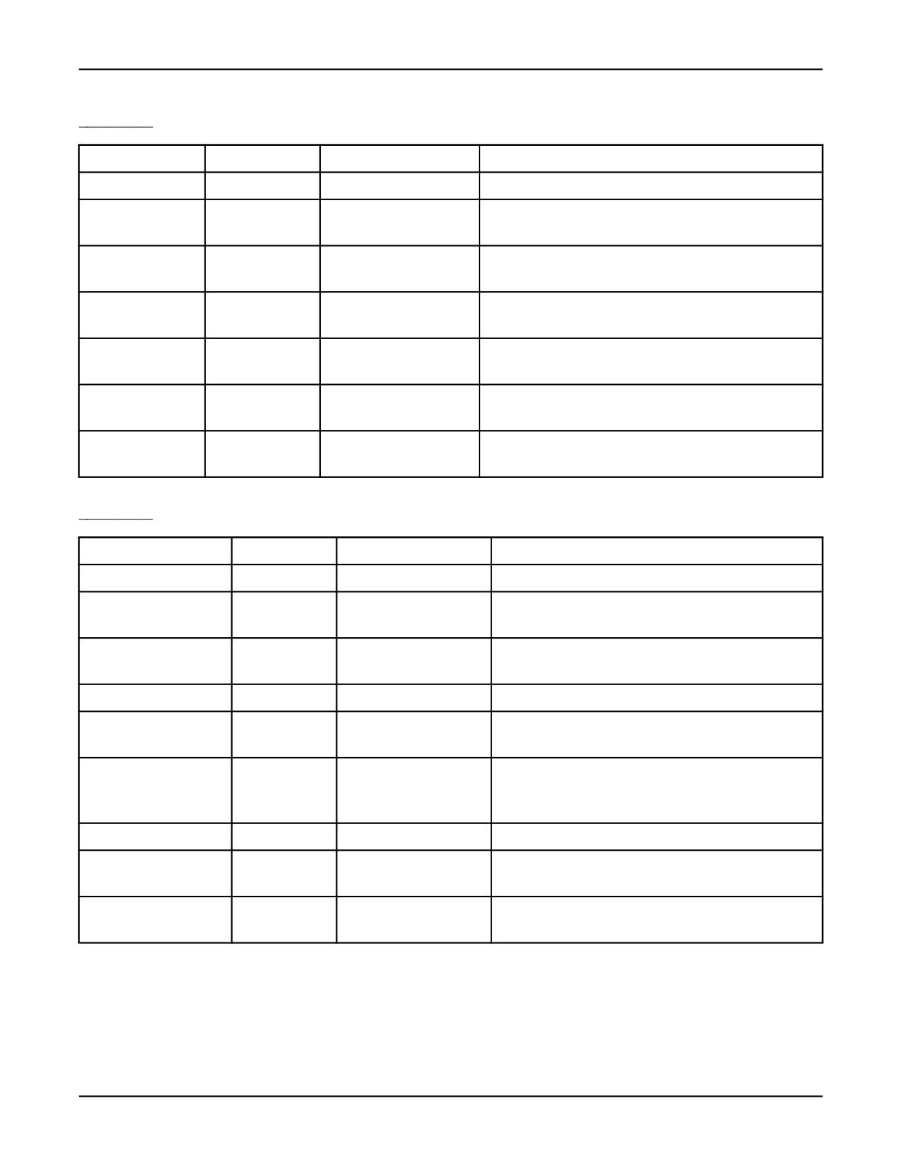
SO[0] - SO[15]. Table 14-1 lists each standard operator panel input signal. Table 14-2 lists each
standard operator panel output signal.
14-6
MARRC75KR07091E Rev D
14. INPUT/OUTPUT SYSTEM
Table 14-1. Standard Operator Panel Input Signals
OPIN[n]
SI[n]
Function
Description
OPIN[0]
SI[0]
NOT USED
-
OPIN[1]
SI[1]
FAULT RESET
This signal is normally turned OFF, indicating that the
FAULT RESET button is not being pressed.
OPIN[2]
SI[2]
REMOTE
This signal is normally turned OFF, indicating that the
controller is not set to remote.
OPIN[3]
SI[3]
HOLD
This signal is normally turned ON, indicating that the
HOLD button is not being pressed.
OPIN[6]
SI[6]
CYCLE START
This signal is normally turned OFF, indicating that the
CYCLE START button is not being pressed.
OPIN[7] - OPIN[15]
SI[7], SI[10] -
NOT USED
-
SI[15]
SI[8] SI[9]
CE/CR Select b0
This signal is two bits and indicates the status of the
CE/CR Select b1
mode select switch.
Table 14-2.
Standard Operator Panel Output Signals
OPOUT[n]
SOI[n]
Function
Description
OPOUT[0]
SO[0]
REMOTE LED
This signal indicates that the controller is set to remote.
OPOUT[1]
SO[1]
CYCLE START
This signal indicates that the CYCLE START button
has been pressed or that a program is running.
OPOUT[2]
SO[2]
HOLD
This signal indicates that the HOLD button has been
pressed or that a hold condition exists.
OPOUT[3]
SO[3]
FAULT LED
This signal indicates that a fault has occurred.
OPOUT[4]
SO[4]
BATTERY ALARM
This signal indicates that the CMOS battery voltage
is low.
OPOUT[5]
SO[5]
USER LED#1 (PURGE
This signal is user-definable.
COMPLETE for
P-series robots)
OPOUT[6]
SO[6]
USER LED#2
This signal is user-definable.
OPOUT[7]
SO[7]
TEACH PENDANT
This signal indicates that the teach pendant is enabled.
ENABLED
OPOUT[8] -
SO[8] - SO[15]
NOT USED
-
OPOUT[15]
14-7
14. INPUT/OUTPUT SYSTEM
MARRC75KR07091E Rev D
User Operator Panel Input and Output Signals
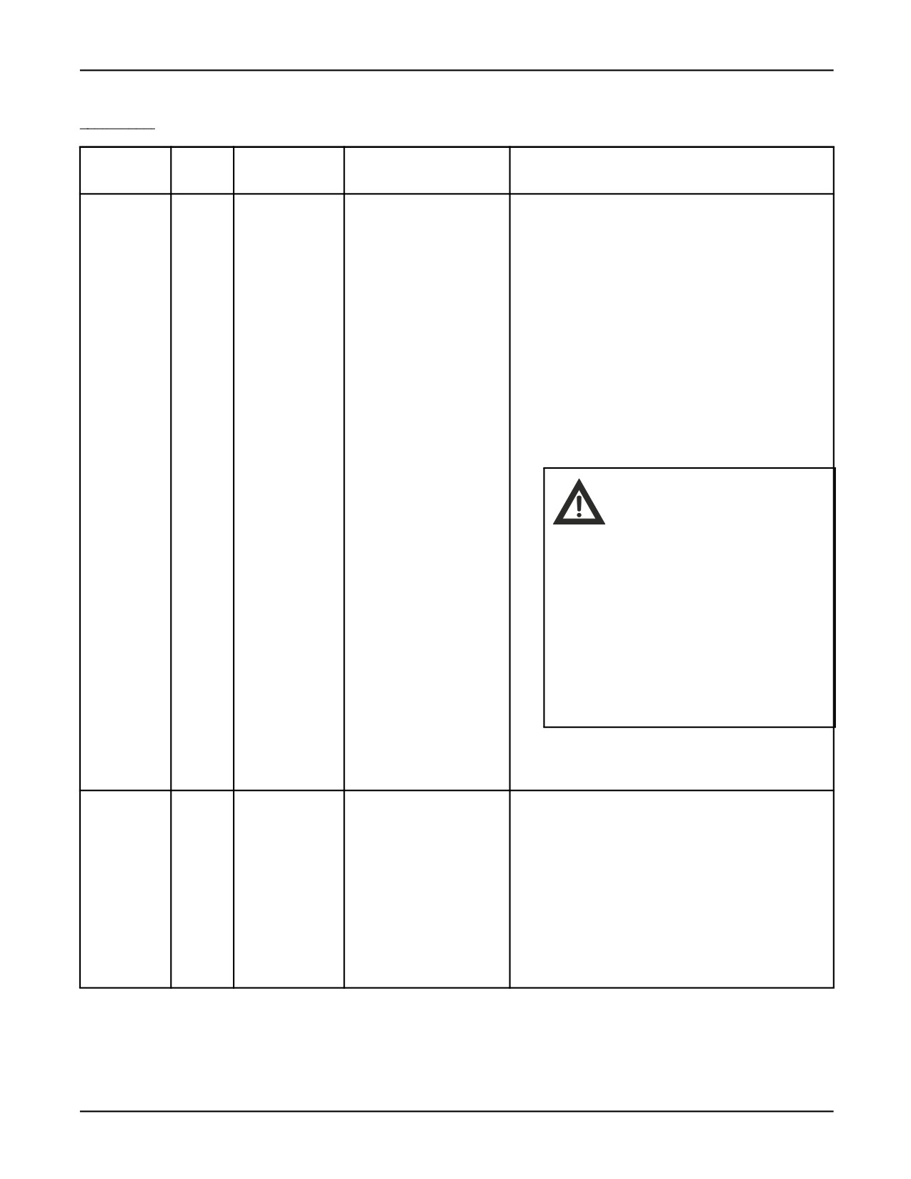
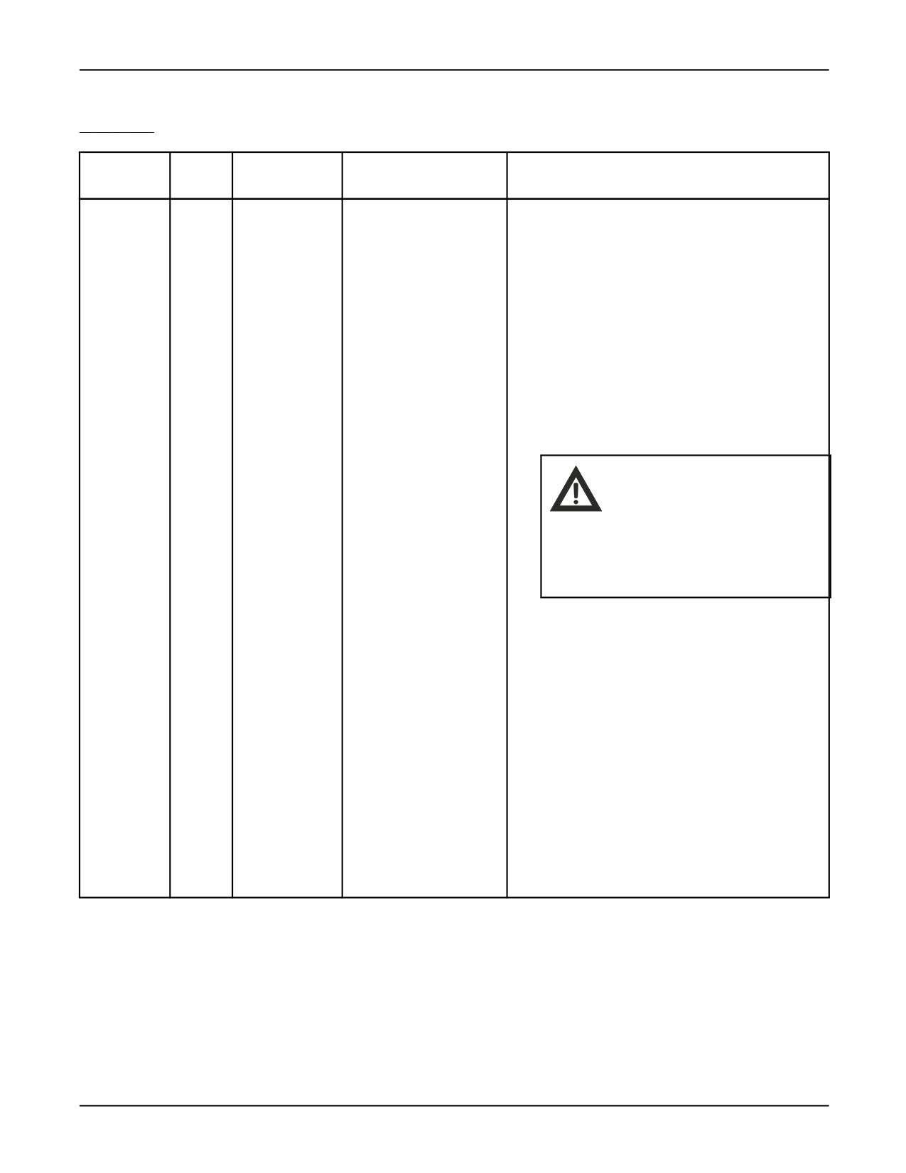
User operator panel input and output signals are recognized by the KAREL system as OPIN[16]-
OPIN[33] and OPOUT[16]-OPOUT[35] and by the screens on the teach pendant as UI[1]-UI[18]
and UO[1]-UO[20]. On the process I/O board, UOP input signals are mapped to the first 18 digital
input signals and UOP output signals are mapped to the first 20 digital output signals. Table 14-3 lists
and describes each user operator panel input signal. Table 14-4 lists each user operator panel output
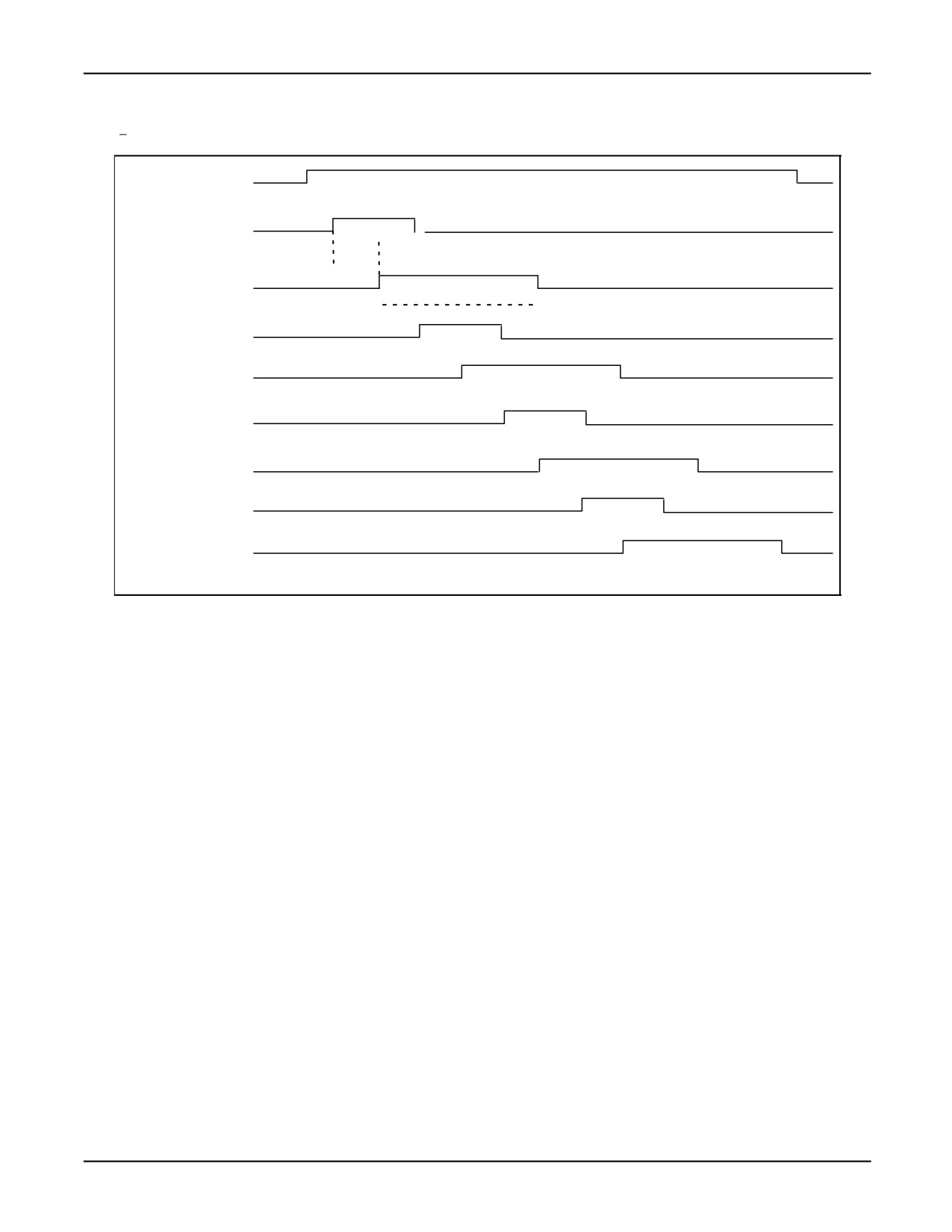
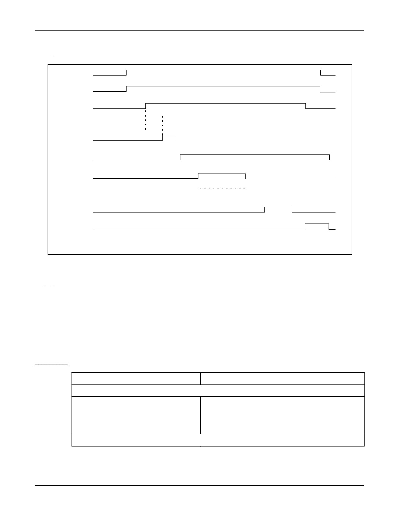
signal. Figure 14-2 and Figure 14-3 illustrate the timing of the UOP signals.
14-8
MARRC75KR07091E Rev D
14. INPUT/OUTPUT SYSTEM
Table 14-3.
User Operator Panel Input Signals
OPIN[n]
UI[n]
Process I/O
Function
Description
Number
OPIN[16]
UI[1]
1
*IMSTP
*IMSTP is the immediate stop software signal.
Always active
*IMSTP is a normally OFF signal held ON that when
set to OFF will
•
Pause a program if running.
•
Shut off power to the servos.
•
Immediately stop the robot and applies robot
brakes.
Error code SRVO-037 *IMSTP Input (Group:i)
will be displayed when this signal is lost. This
signal is always active.
Warning
*IMSTP is a software controlled
input and cannot be used
for safety purposes. Use
*IMSTP with EMG1, EMG2, and
EMGCOM to use this signal
with a hardware controller
emergency stop. Refer to
the Maintenance Manual,
specific to your robot model,
for connection information of
EMG1, EMG2, and EMGCOM.
OPIN[17]
UI[2]
2
*HOLD
*HOLD is the external hold signal. *HOLD is a
Always active
normally OFF signal held ON that when set to OFF
will
• Pause program execution.
• Slow motion to a controlled stop and hold.
• Optional Brake on Hold shuts off servo power
after the robot stops.
14-9

14. INPUT/OUTPUT SYSTEM
MARRC75KR07091E Rev D
Table 14-3. User Operator Panel Input Signals (Cont’d)
OPIN[n]
UI[n]
Process I/O
Function
Description
Number
OPIN[18]
UI[3]
3
*SFSPD
*SFSPD is the safety speed input signal. This signal
Always active
is usually connected to the safety fence.*SFSPD is a
normally OFF signal held ON that when set OFF will
• Pause program execution.
• Reduce the speed override value to that
defined in a system variable. This value cannot
be increased while *SFSPD is OFF.
• Display error code message MF-0004 Fence
Open.
• Not allow a REMOTE start condition. Start
inputs from UOP or SOP are disabled when
*SFSPD is set to OFF.
14-10
MARRC75KR07091E Rev D
14. INPUT/OUTPUT SYSTEM
Table 14-3.
User Operator Panel Input Signals (Cont’d)
OPIN[n]
UI[n]
Process I/O
Function
Description
Number
OPIN[19]
UI[4]
4
CSTOPI
CSTOPI is the cycle stop input. When CSTOPI
Always active
becomes TRUE, the system variable $CSTOP is
set to TRUE. In addition, if the system variable
$SHELL_CONFIG.$shell_name is not TRUE or
is uninitialized at power up, CSTOPI functions
as follows, depending on the system variable
$SHELL_CFG.$USE_ABORT. If the system
variable $SHELL_CFG.$USE_ABORT is set to
FALSE , the CSTOPI input
• Clears the queue of programs to be executed
that were sent by RSR signals.
Warning
When
$SHELL_CFG.USE_ABORT
is FALSE, CSTOPI does not
immediately stop automatic
program execution.
• Automatic execution will be stopped after the
current program has finished executing.
If the system variable
$SHELL_CFG.$USE_ABORT is set
to TRUE, the CSTOPI input
• Clears the queue of programs to be executed
that were sent by RSR signals.
• Immediately aborts the currently executing
program for programs that were sent to be
executed by either RSR or PNS.
14-11

14. INPUT/OUTPUT SYSTEM
MARRC75KR07091E Rev D
Table 14-3.
User Operator Panel Input Signals (Cont’d)
OPIN[n]
UI[n]
Process I/O
Function
Description
Number
OPIN[20]
UI[5]
5
FAULT_RESET
FAULT_RESET is the external fault reset signal.
Always active
When this signal is received
• Error status is cleared.
• Servo power is turned ON.
• A paused program will not be resumed.
OPIN[21]
UI[6]
6
START
START is the remote start input. How this
Active when the robot
signal functions depends on the system variable
is in a remote condition
$SHELL_CFG.$CONT_ONLY. If the system
(CMDENBL = ON)
variable $SHELL_CFG.$CONT_ONLY is set to
FALSE , the START input signal will
• Resume a paused program.
• If a program is not paused, the currently
selected program starts from the position of the
cursor.
If the system variable
$SHELL_CFG.$CONT_ONLY is set
to TRUE, the START input signal will
• Resume a paused program only. The
PROD_START input must be used to start a
program from the beginning.
OPIN[22]
UI[7]
7
HOME
HOME is the home input. When this signal is
Active when the robot is
received the robot moves to the defined home
in a remote condition
position.
OPIN[23]
UI[8]
8
ENBL
ENBL is the enable input. This signal must be ON
Always active
to have motion control ability. When this signal is
OFF, robot motion can be done. When ENBL is ON
and the REMOTE switch on the operator panel is
in the REMOTE position, the robot is in a remote
operating condition.
14-12

MARRC75KR07091E Rev D
14. INPUT/OUTPUT SYSTEM
Table 14-3.
User Operator Panel Input Signals (Cont’d)
OPIN[n]
UI[n]
Process I/O
Function
Description
Number
OPIN[24]-
UI[9]-
9- 126
RSR1/PNS1,
RSR1-8 are the robot service request input
OPIN[31]
UI[16]
RSR2/PNS2,
signals. When one of these signals is received,
RSR3/PNS3,
the corresponding RSR program is executing
RSR4/PNS4,RSR5/PNS5,
or, or a program is running currently, stored in a
,RSR6/PNS6,
queue for later execution. RSR signals are used
,RSR7/PNS7,
for production operation and can be received while
,RSR8/PNS8
an ACK output is being pulsed. See Figure 14-2 .
Active when the robot
PNS 1-8 are program number select input signals.
is in a remote condition
PNS selects programs for execution, but does not
(CMDENBL = ON)
execute programs . Programs that are selected
by PNS are executed using the START input or the
PROD_START input depending on the value of the
system variable $SHELL_CFG.$CONT_ONLY.The
PNS number is output by pulsing the SNO signal
(selected number output) and the SNACK signal
(selected number acknowledge). See Figure 14-3 .
OPIN[32]
UI[17]
17
PNSTROBE Active when
The PNSTROBE input is the program number select
the robot is in a remote
strobe input signal. See Figure 14-3 .
condition (CMDENBL =
ON)
OPIN[33]
UI[18]
18
PROD_START Active
The PROD_START input, when used with PNS, will
when the robot is in
initiate execution of the selected program from the
a remote condition
PNS lines. When used without PNS, PROD_START
(CMDENBL = ON)
executes the selected program from the current
cursor position. See Figure 14-3 .
14-13

14. INPUT/OUTPUT SYSTEM
MARRC75KR07091E Rev D
Table 14-4.
User Operator Panel Output Signals
OPOUT[n]
UO[n]
Process I/O
Function
Description
Number
OPOUT[16]
UO[1]
1
CMDENBL
CMDENBL is the command enable output.
This output indicates that the robot is in
a remote condition. This signal goes ON
when the REMOTE switch is turned to ON
or when the ENBL input is received. This
output only stays on when the robot is not
in a fault condition. See Figure 14-2 and
Figure 14-3 .
OPOUT[17]
UO[2]
2
SYSRDY
SYSRDY is the system ready output. This
output indicates that servos are turned
ON.
OPOUT[18]
UO[3]
3
PROGRUN
PROGRUN is the program run output.
This output turns on when a program is
running. See Figure 14-3 .
OPOUT[19]
UO[4]
4
PAUSED
PAUSED is the paused program output.
This output turns on when a program is
paused.
OPOUT[20]
UO[5]
5
HELD
HELD is the hold output. This output turns
on when the SOP HOLD button has been
pressed, or the UOP *HOLD input is OFF.
OPOUT[21]
UO[6]
6
FAULT
FAULT is the error output. This output
turns on when a program is in an error
condition.
OPOUT[22]
UO[7]
7
ATPERCH
Not supported. Refer to the appropriate
application-specific FANUC Robotics
Setup and Operations Manual ,
“Reference Position Utility” section.
OPOUT[23]
UO[8]
8
TPENBL
TPENBL is the teach pendant enable
output. This output turns on when the
teach pendant is on.
OPOUT[24]
UO[9]
9
BATALM
BATALM is the battery alarm output. This
output turns on when the CMOS RAM
battery voltage goes below 3.6 volts.
OPOUT[25]
UO[10]
10
BUSY
BUSY is the processor busy output. This
signal turns on when the robot is executing
a program or when the processor is busy.
14-14

MARRC75KR07091E Rev D
14. INPUT/OUTPUT SYSTEM
Table 14-4.
User Operator Panel Output Signals (Cont’d)
OPOUT[n]
UO[n]
Process I/O
Function
Description
Number
OPOUT[26]
UO[11]- UO[18]
11-
18
ACK1/SNO1,
ACK 1-8 are the acknowledge signals
OPOUT[33]
ACK2/SNO2,
output 1 through 4. These signals turn
ACK3/SNO3,
on when the corresponding RSR signal
ACK4/SNO4,
is received. See Figure 14-2 SNO 1-8
ACK5/SNO5,
are the signal number outputs. These
ACK6/SNO6,
signals carry the 8-bit representation
ACK7/SNO7,
of the corresponding PNS selected
ACK8/SNO8
program number. If the program cannot be
represented by an 8-bit number, the signal
is set to all zeroes or off. See Figure 14-3 .
OPOUT[34]
UO[19]
19
SNACK
SNACK is the signal number acknowledge
output. This output is pulsed if the program
is selected by PNS input. See Figure 14-3
OPOUT[35]
UO[20]
20
RESERVED
-
OPOUT[36]
UO[21]
21
UNCAL (option)
UNCAL is the uncalibrated output. This
output turns on when the robot is not
calibrated. The robot is uncalibrated
when the controller loses the feedback
signals from one or all of the motors. Set
$OPWORK.$OPT_OUT = 1 to use this
signal.
OPOUT[37]
UO[22]
22
UPENBL (option)
UPENBL is the user panel enable output.
This output indicates that the robot is
in a remote condition. This signal goes
on when the remote switch is turned to
ON or when the ENBL input is received.
This output will stay on even if the
robot is in a fault condition. Set
$OPWORK.$OPT_OUT = 1 to use this
signal.
OPOUT[38]
UO[23]
23
LOCKED (option)
-
OPOUT[39]
UO[24]
24
CSTOPO (option)
CSTOPO is the cycle stop output.
This output turns on when the
CSTOPI input has been received.
Set $OPWORK.$OPT_OUT = 1 to use
this signal.
14-15
14. INPUT/OUTPUT SYSTEM
MARRC75KR07091E Rev D
Figure 14-2. RSR Timing Diagram
CMDENBL
Remote Condition
OUTPUT
RSR1
INPUT
$SCR.$cond_time milliseconds maximum delay
ACK1
OUTPUT
Pulse width is specified in RSR Setup screen
RSR2
INPUT
ACK2
OUTPUT
RSR3
INPUT
ACK3
OUTPUT
RSR4
INPUT
ACK4
OUTPUT
Another RSR signal can be received while an ACK is being pulsed
14-16
MARRC75KR07091E Rev D
14. INPUT/OUTPUT SYSTEM
Figure 14-3. PNS Timing Diagram
CMDENBL
Remote Condition
OUTPUT
PNS 1 8
Program Number is Selected
INPUT
PNSTROBE
INPUT
While PNSTROBE is ON, program selection modification is not allowed
PNS selected program is read within 32 ms from PNSTROBE rising edge
PNSTROBE
DETECTION
SNO1 8
OUTPUT
SNACK
OUTPUT
Pulse width is specified
in PNS Setup screen.
PROD_START
INPUT
PROGRUN
OUTPUT
Program is run within 32
ms from PROD_START
falling edge.
14.2.3
Teach Pendant Input and Output Signals (TPIN/TPOUT)
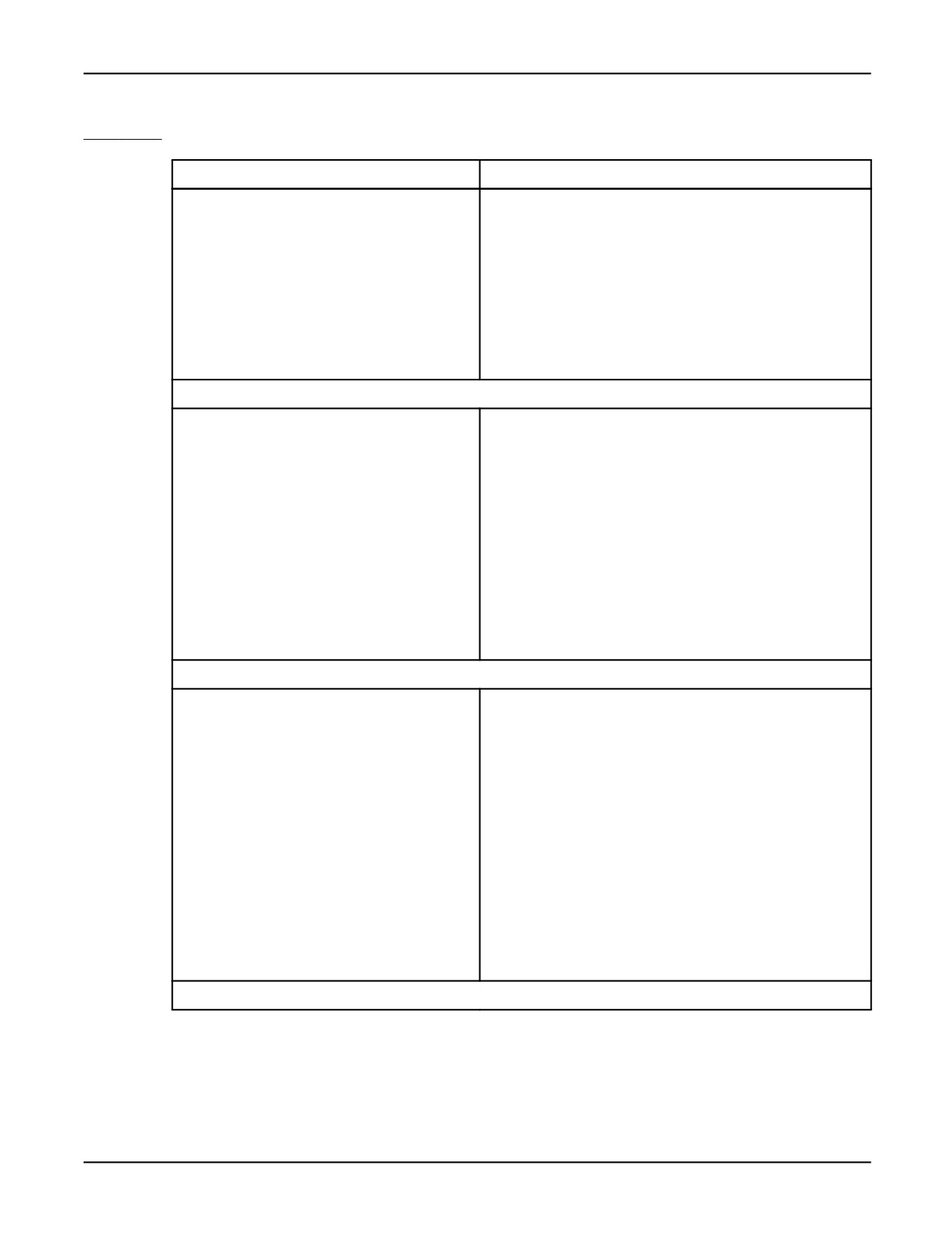
The teach pendant input signals (TPIN) provide read access to input signals generated by the teach
pendant keys. Teach pendant inputs can be accessed through the TPIN port arrays. A KAREL
program treats teach pendant input data as a BOOLEAN data type. The value is either ON (active--the
key is pressed) or OFF (inactive--the key is not pressed). TPIN signals are accessed in KAREL
programs by the name TPIN[n], where “n” is the signal number, which is assigned internally. Refer to
Table 14-5 for teach pendant input signal assignments.
Table 14-5. Teach Pendant Input Signal Assignments
TPIN[n]
Teach Pendant Key
EMERGENCY STOP AND DEADMAN
TPIN[250]
EMERGENCY STOP
TPIN[249]
ON/OFF switch
TPIN[247]
Right DEADMAN switch
TPIN[248]
Left DEADMAN switch
Arrow Keys
14-17
14. INPUT/OUTPUT SYSTEM
MARRC75KR07091E Rev D
Table
14-5.
Teach Pendant Input Signal Assignments (Cont’d)
TPIN[n]
Teach Pendant Key
TPIN[212]
Up arrow
TPIN[213]
Down arrow
TPIN[208]
Right arrow
TPIN[209]
Left arrow
TPIN[0]
Left and/or right shift
TPIN[204]
Shifted Up arrow
TPIN[205]
Shifted Down arrow
TPIN[206]
Shifted Right arrow
TPIN[207]
Shifted Left arrow
Keypad Keys (shifted or unshifted)
TPIN[13]
ENTER
TPIN[8]
BACK SPACE
TPIN[48]
0
TPIN[49]
1
TPIN[50]
2
TPIN[51]
3
TPIN[52]
4
TPIN[53]
5
TPIN[54]
6
TPIN[55]
7
TPIN[56]
8
TPIN[57]
9
Function Keys
TPIN[128]
PREV
TPIN[129]
F1
TPIN[131]
F2
TPIN[132]
F3
TPIN[133]
F4
TPIN[134]
F5
TPIN[135]
NEXT
TPIN[136]
Shifted PREV
TPIN[137]
Shifted F1
TPIN[138]
Shifted F2
TPIN[139]
Shifted F3
TPIN[140]
Shifted F4
TPIN[141]
Shifted F5
TPIN[142]
Shifted NEXT
Menu Keys
14-18

MARRC75KR07091E Rev D
14. INPUT/OUTPUT SYSTEM
Table
14-5.
Teach Pendant Input Signal Assignments (Cont’d)
TPIN[n]
Teach Pendant Key
TPIN[143]
SELECT
TPIN[144]
MENU
TPIN[145]
EDIT
TPIN[146]
DATA
TPIN[147]
FCTN
TPIN[148]
ITEM
TPIN[149]
+%
TPIN[150]
-%
TPIN[151]
HOLD
TPIN[152]
STEP
TPIN[153]
RESET
TPIN[240]
DISP
TPIN[203]
HELP
TPIN[154]
Shifted ITEM
TPIN[155]
Shifted +%
TPIN[156]
Shifted -%
TPIN[157]
Shifted STEP
TPIN[158]
Shifted HOLD
TPIN[159]
Shifted RESET
TPIN[227]
Shifted DISP
TPIN[239]
Shifted HELP
User Function Keys
TPIN[173]
USER KEY 1
TPIN[174]
USER KEY 2
TPIN[175]
USER KEY 3
TPIN[176]
USER KEY 4
TPIN[177]
USER KEY 5
TPIN[178]
USER KEY 6
TPIN[210]
USER KEY 7
TPIN[179]
Shifted USER KEY
1
TPIN[180]
Shifted USER KEY
2
TPIN[181]
Shifted USER KEY
3
TPIN[182]
Shifted USER KEY
4
TPIN[183]
Shifted USER KEY
5
TPIN[184]
Shifted USER KEY
6
TPIN[211]
Shifted USER KEY
7
Motion Keys
14-19

14. INPUT/OUTPUT SYSTEM
MARRC75KR07091E Rev D
Table
14-5.
Teach Pendant Input Signal Assignments (Cont’d)
TPIN[n]
Teach Pendant Key
TPIN[185]
FWD
TPIN[186]
BWD
TPIN[187]
COORD
TPIN[28]
GROUP
TPIN[188]
+X
TPIN[189]
+Y
TPIN[190]
+Z
TPIN[191]
+X rotation
TPIN[192]
+Y rotation
TPIN[193]
+Z rotation
TPIN[12290]
+J7
TPIN[12294]
+J8
TPIN[194]
-X
TPIN[195]
-Y
TPIN[196]
-Z
TPIN[197]
-X rotation
TPIN[198]
-Y rotation
TPIN[199]
-Z rotation
TPIN[12292]
-J7
TPIN[12296]
-J8
TPIN[226]
Shifted FWD
TPIN[207]
Shifted BWD
TPIN[202]
Shifted COORD
Motion Keys Cont’d
TPIN[214]
Shifted +X
TPIN[215]
Shifted +Y
TPIN[216]
Shifted +Z
TPIN[217]
Shifted +X rotation
TPIN[218]
Shifted +Y rotation
TPIN[219]
Shifted +Z rotation
TPIN[12291]
Shifted +J7
TPIN[12295]
Shifted +J8
TPIN[220]
Shifted -X
TPIN[221]
Shifted -Y
TPIN[222]
Shifted -Z
TPIN[223]
Shifted -X rotation
TPIN[224]
Shifted -Y rotation
TPIN[225]
Shifted -Z rotation
TPIN[12293]
Shifted -J7
TPIN[12297]
Shifted -J8
i Keys
14-20

MARRC75KR07091E Rev D
14. INPUT/OUTPUT SYSTEM
Table
14-5.
Teach Pendant Input Signal Assignments (Cont’d)
TPIN[n]
Teach Pendant Key
TPIN[12288]
i
key
TPIN[12298]
i
MENU, Top Menu
TPIN[12299]
i
SELECT, 4D Select Node Map
TPIN[12300]
i
EDIT, 4D Position Register
TPIN[12301]
i
DATA, 4D Edit Node Map
TPIN[12302]
i
FCTN, Related Views
TPIN[12303]
i
STEP
TPIN[12304]
i
COORD
TPIN[12305]
i
GROUP
TPIN[12306]
i
+%
TPIN[12307]
i
-%
TPIN[12308]
i
Up arrow
TPIN[12309]
i
Down arrow
TPIN[12310]
i
Right arrow
TPIN[12311]
i
Left arrow
TPIN[12312]
i
DISP, Focus window
TPIN[12313]
i
HELP
TPIN[12338]
i
USER KEY 7, 4D Display
TPIN[12339]
i
USER KEY 6
TPIN[12340]
i
USER KEY 5
TPIN[12341]
i
ENTER, space
i Keys Cont’d
TPIN[12314]
i
+X
TPIN[12315]
i
+Y
TPIN[12316]
i
+Z
TPIN[12317]
i
+X rotation
TPIN[12318]
i
+Y rotation
TPIN[12319]
i
+Z rotation
TPIN[12320]
i
+J7 rotation
TPIN[12321]
i
+J8 rotation
TPIN[12322]
i
-X
TPIN[12323]
i
-Y
TPIN[12324]
i
-Z
TPIN[12325]
i
-X rotation
TPIN[12326]
i
-Y rotation
TPIN[12327]
i
-Z rotation
TPIN[12328]
i
-J7 rotation
TPIN[12329]
i
-J8 rotation
Three teach pendant output signals are available for use:
• TPOUT[6] - controls teach pendant USER LED #1
14-21
14. INPUT/OUTPUT SYSTEM
MARRC75KR07091E Rev D
• TPOUT[7] - controls teach pendant USER LED #2
• TPOUT[8] - controls teach pendant USER LED #3
14.3
Serial Input/Output
14.3.1
Serial Input/Output
The serial I/O system allows you to communicate with peripheral serial devices connected to
the KAREL system. For example, you could use serial I/O to write messages from one of the
communications ports to a remote terminal across a cable that connects to the controller.
To use serial I/O you must provide a serial device and the appropriate cable. Refer to the Maintenance
Manual, specific to your robot model, for electrical specifications.
The communications ports that you use to read and write serial data are defined in the system
software. Each software port is associated with physical connectors on the controller to which you
attach the communications cable.
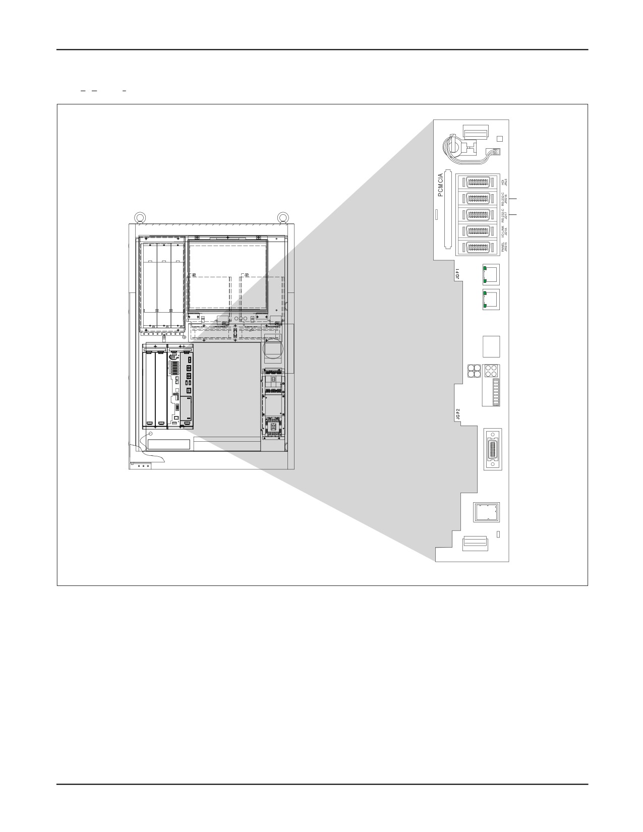
Figure 14-4 shows the location of the ports on the controller.
14-22
MARRC75KR07091E Rev D
14. INPUT/OUTPUT SYSTEM
Figure 14-4. Location of Ports on the Controller
MAIN
(SLOT 1)
CP8B
P2
P3/P4
ETHERNET
TX
CD38A
L/RX
TX
CD38B
L/RX
ALARM
STATUS
1
2
3
4
CA69A
JRL6
FSSB
C0P10A
CRS26
Ports
Setting up a port means initializing controller serial ports to use specific devices, such as the CRT/KB.
Initializing ports involves setting up specific information for a port based on the kind of device that
will connect to the port. This is done on the teach pendant PORT INIT screen.
The controller supports up to four serial ports. Several different kinds of devices can be connected to
these ports.
14-23
14. INPUT/OUTPUT SYSTEM
MARRC75KR07091E Rev D
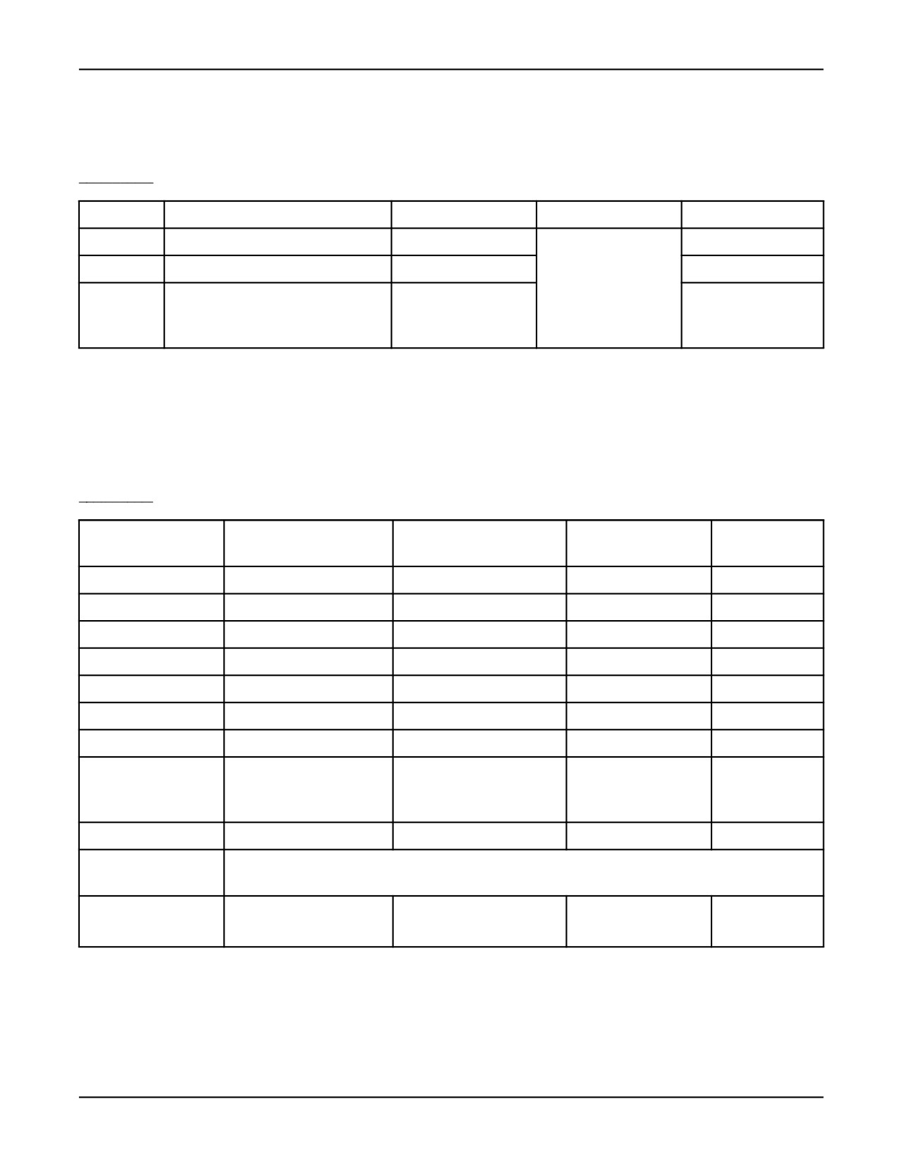
Up to four ports are available, P1-P4. Table 14-6 lists the ports. You can set up ports P2 through P4 if
you have them, but you cannot set up the teach pendant port, P1.
Table 14-6. Ports P1 - P4
Port
Item Name on Screen
Kind of Port
Use
Default Device
P2
JRS16 RS-232-C
RS-232-C
Any device
Maintenance Console
P3
JD17 RS-232-C on Main CPU card
RS-232-C
KCL
P4
JD17 on Main CPU card. This port
RS-422
No use
is displayed on the teach pendant if
$RS232_NPORT=4.
Devices
You can modify the default communications settings for each port except port 1, which is dedicated
to the teach pendant (TP). Table 14-7 lists the default settings for each kind of device you can
connect to a port.
Table 14-7. Default Communications Settings for Devices
Timeout Value
Device
Speed (baud)
Parity Bit
Stop Bit
(sec)
Sensor*
4800
Odd
1 bit
0
Host Comm.*
4800
Odd
1 bit
0
KCL/CRT
9600
None
1 bit
0
Maintenance Console
9600
None
1 bit
0
Factory Terminal
9600
None
1 bit
0
TP Demo Device
9600
None
1 bit
0
No Use
9600
None
1 bit
0
Current Position (for
9600
None
1 bit
0
use with the Current
Position option)
PMC Programmer
9600
None
2 bit
0
Modem/PPP
Refer to the FANUC Robotics Internet Options Setup and Operations Manual for information on the
supported modems.
HMI Device
19200
Odd
1 bit
0
*You can adjust these settings; however, if you do, they might not function as intended because they
are connected to an external device.
14-24
MARRC75KR07091E Rev D
14. INPUT/OUTPUT SYSTEM
After the hardware has been connected and the appropriate port is configured and the external
port is connected, you can use KAREL language OPEN FILE, READ, and WRITE statements to
communicate with the peripheral device.
Higher levels of communication protocol are supported as an optional feature.
See Also: Appendix A for more information on the statements and built-ins available in KAREL
Refer to the application-specific FANUC Robotics Setup and Operations Manual for more information
about setting up ports.
14-25
Chapter 15
MULTI-TASKING
Contents
Chapter 15
MULTI-TASKING
15-1
15.1
MULTI-TASKING TERMINOLOGY
15-2
15.2
INTERPRETER ASSIGNMENT
15-3
15.3
MOTION CONTROL
15-3
15.4
TASK SCHEDULING
15-4
15.4.1
Priority Scheduling
15-5
15.4.2
Time Slicing
15-6
15.5
STARTING TASKS
15-6
15.5.1
Running Programs from the User Operator Panel (UOP) PNS
Signal
15-7
15.5.2
Child Tasks
15-7
15.6
TASK CONTROL AND MONITORING
15-7
15.6.1
From TPP Programs
15-8
15.6.2
From KAREL Programs
15-8
15.6.3
From KCL
15-8
15.7
USING SEMAPHORES AND TASK SYNCHRONIZATION
15-9
15.8
USING QUEUES FOR TASK COMMUNICATIONS
15-14
15-1
15. MULTI-TASKING
MARRC75KR07091E Rev D
Multi-tasking allows more than one program to run on the controller on a time-sharing basis, so that
multiple programs appear to run simultaneously.
Multi-tasking is especially useful when you are executing several sequences of operations which
can generally operate independently of one another, even though there is some interaction between
them. For example:
• A process of monitoring input signals and setting output signals.
• A process of generating and transmitting log information to a cell controller and receiving
commands or other input data from a cell controller.
It is important to be aware that although multiple tasks seem to operate at the same time, they are
sharing use of the same processor, so that at any instant only one task is really being executed. With
the exception of interruptible statements, once execution of a statement is started, it must complete
before statements from another task can be executed. The following statements are interruptible:
• READ
• DELAY
• WAIT
• WAIT FOR
Refer to Section 15.4 , “Task Scheduling” for information on how the system decides which task
to execute first.
15.1
MULTI-TASKING TERMINOLOGY
The following terminology and expressions are used in this chapter.
• Task or User task
A task, or user task, is a user program that is running or paused. A task is executed by an
"interpreter." A task is created when the program is started and eliminated when the interpreter it
is assigned to, becomes assigned to another task.
• Interpreter
An interpreter is a system component that executes user programs. At a cold or controlled start,
($MAXNUMTASKS + 2) interpreters are created. These interpreters are capable of concurrently
executing tasks.
• Task name
Task name is the program name specified when the task is created. When you create a task,
specify the name of the program to be executed as the task name.
15-2
MARRC75KR07091E Rev D
15. MULTI-TASKING
Note The task name does not change once the task is created. Therefore, when an external routine
is executing, the current executing program name is not the same as the task name. When you
send any requests to the task, use the task name, not the current program name.
• Motion control
Motion control is defined by a bit mask that specifies the motion groups of which a task has
control. Only one task at a time can control a motion group. However, different tasks can
control different motion groups simultaneously. Refer to Section 15.3 , “Motion Control,” for
more information.
15.2
INTERPRETER ASSIGNMENT
When a task is started, it is assigned to an interpreter. The interpreter it is assigned to (1, 2, 3, ...)
determines its task number. The task number is used in PAUSE PROGRAM, ABORT PROGRAM
and CONTINUE PROGRAM condition handler actions. The task number for a task can be determined
using the GET_TSK_INFO built-in.
The following are rules for assigning a task to an interpreter:
• If the task is already assigned to an interpreter, it uses the same interpreter.
• A task is assigned to the first available interpreter that currently has no tasks assigned to it.
• If all interpreters are assigned to tasks, a new task will be assigned to the first interpreter that
has an aborted task.
• If none of the above can be done, the task cannot be started.
15.3
MOTION CONTROL
An important restriction in multi-tasking is in the control of the various motion groups. Only one
task can have control, or use of, a group of axes. A task requires control of the group(s) in the
following situations:
• When the task starts, if the controller directive %NOLOCKGROUP is not used. If the
%LOCKGROUP directive is not used, the task requires control of all groups by default. If
%LOCKGROUP is used, control of the specified groups is required.
For teach pendant programs, motion control is required when the program starts, unless the
DETAIL page from the SELECT screen is used to set the Group Mask to [*,*,*,*,*].
• When a task executes the LOCK_GROUP built-in, it requires the groups specified by the group
mask.
15-3
15. MULTI-TASKING
MARRC75KR07091E Rev D
• When a task calls a ROUTINE or teach pendant program, it requires control of those group(s).
The group(s) required by a ROUTINE or TPP+ program are those specified, or implied, by
controller directives or in the teach pendant DETAIL setup.
A task will be given control of the required group(s), assuming:
• No other task has control of the group.
• The teach pendant is not enabled, with the exception that motion control can be given to a program
when it is started using shift-FWD at the teach pendant or if it has the %TPMOTION directive.
• There are no emergency stops active.
• The servos are ready.
• The UOP signal IMSTP is not asserted.
A task will be paused if it is not able to get control of the required group(s).
After a task gets control of a group, it keeps it until one of the following:
• The task ends (aborts).
• The task executes the UNLOCK_GROUP built-in.
• The task passes control of the group(s) in a RUN_TASK built-in.
• The ROUTINE or teach pendant program returns, and groups were required by a ROUTINE or
teach pendant program, but not by the calling program.
15.4
TASK SCHEDULING
A task that is currently running (not aborted or paused) will execute statements until one of the
following:
• A hold condition occurs.
• A higher priority program becomes ready to run.
• The task time slice expires.
• The program aborts or pauses.
The following are examples of hold conditions:
• Waiting for a read operation to complete.
• Waiting for a motion to complete.
• Waiting for a WAIT, WAIT FOR, or DELAY statement to complete.
15-4
MARRC75KR07091E Rev D
15. MULTI-TASKING
A task is ready to run when it is in running state and has no hold conditions. Only one task is
actually executed at a time. There are two rules for determining which task will be executed when
more than one task is ready to run:
• Priority - If two or more tasks of different priority are ready to run, the task with higher priority is
executed first. Refer to Section 15.4.1 , “Priority Scheduling,” for more information.
• Time-slicing - If two tasks of the same priority are ready to run, execution of the tasks is
time-sliced. Refer to Section 15.4.2 , “Time Slicing,” for more information.
15.4.1
Priority Scheduling
If two or more tasks with different priorities are ready to run, the task with the highest priority will run
first. The priority of a task is determined by its priority number. Priority numbers must be in the range
from -8 to 143. The lower the priority number, the higher the task priority.
For example: if TASK_A has a priority number of 50 and TASK_B has a priority number of 60, and
both are ready to run, TASK_A will execute first, as long as it is ready to run.
A task priority can be set in one of the following ways:
• By default, each user task is assigned a priority of 50.
• KAREL programs may contain the %PRIORITY translator directive.
• The SET_TSK_ATTR built-in can be used to set the current priority of any task.
In addition to affecting other user tasks, task priority also affects the priority of the interpreter
executing it, relative to that of other system functions. If the user task has a higher priority (lower
priority number) than the system function, as long as the user task is ready to run, the system function
will be not be executed. The range of user task priorities is restricted at the high priority end. This is
done so that the user program cannot interfere with motion interpolation. Motion interpolation refers
to the updates required to cause a motion to complete.
The following table indicates the priority of some other system functions.
Table
15-1.
System Function Priority Table
Priority
System Function
Effect of Delaying Function
-8
Maximum priority
New motions delayed.
-1
Motion Planner
New motions delayed.
4
TP Jog
Jogging from the Teach Pendant delayed.
54
Error Logger
Update of system error log delayed.
73
KCL
Execution of KCL commands delayed.
15-5
15. MULTI-TASKING
MARRC75KR07091E Rev D
Table 15-1. System Function Priority Table (Cont’d)
Priority
System Function
Effect of Delaying Function
82
CRT manager
Processing of CRT soft-keys delayed.
88
TP manager
General teach pendant activity delayed.
143
Lowest priority
Does not delay any of the above.
15.4.2
Time Slicing
If two or more tasks of the same priority are ready to run, they will share the system resources by
time-slicing, or alternating use of the system.
A time-slice permits other tasks of the same priority to execute, but not lower priority tasks.
The default time-slice for a task is 256 msec. Other values can be set using the %TIMESLICE
directive or the SET_TSK_ATTR built-in.
15.5
STARTING TASKS
There are a number ways to start a task.
• KCL RUN command. Refer to Appendix C ,“KCL Command Alphabetic Descriptions.”
• Operator Panel start key. Refer to the appropriate application- specific FANUC Robotics Setup
and Operations Manual.
• User operator panel start signal. Refer to the appropriate application-specific FANUC Robotics
Setup and Operations Manual.
• User operator panel PNS signal. Refer to Section 15.5.1 ,“Running Programs from the User
Operator Panel (UOP) PNS Signal,” for more information.
• Teach pendant shift-FWD key. Refer to the appropriate application-specific FANUC Robotics
Setup and Operations Manual , Chapter on “Testing a Program and Running Production,” for
more information.
• Teach pendant program executes a RUN instruction. Refer to Section 15.5.2 , “Child Tasks,”
for more information.
• KAREL program executes the RUN_TASK built-in. Refer to Section 15.5.2 , “Child Tasks,”
for more information.
In each case, the task will not start running if it requires motion control that is not available.
15-6
MARRC75KR07091E Rev D
15. MULTI-TASKING
15.5.1
Running Programs from the User Operator Panel (UOP) PNS Signal
A program is executed:
• If the binary value of the UOP PNS signals is non-zero and the UOP PROGSTART signal
is asserted
• If there is currently a program with the name “PNSnnnn,” where nnnn is the decimal value of the
PNS signals plus the current value of $SHELLCFG.$jobbase.
A program is not executed:
• If the binary value of the PNS signals is zero.
Multiple programs can be started in this way, as long as there is no motion group overlap.
If the task name determined from the PNS is in a paused state, the PROGSTART signal is interpreted
as a CONTINUE signal. If $SHELLCFG.$contonly is TRUE, this is the only function of the
PNS/PROGSTART signals.
If $SHELLCFG.$useabort is TRUE, the PNS signals can be used to abort a running task. The name of
the task to be aborted is the same as that used with the PROGSTART signal. In this case, abort is
triggered by the UOP CSTOPI signal
15.5.2
Child Tasks
A running task can create new tasks. This new task is called a child task. The task requesting creation
of the child task is called the parent task. In teach pendant programs, a new task is created by executing
a RUN instruction. In KAREL programs a new task can be created using the RUN_TASK built-in.
The parent and child task may not require the same motion group. In the case of RUN_TASK,
however, it is possible to release control of motion groups for use by the child task.
Once a child task is created, it runs independently of its parent task, with the following exception:
• If a parent task is continued and its child task is paused, the child task is also continued.
• If a parent task is put in STEP mode, the child task is also put in STEP mode.
If you want the child task to be completely independent of the parent, a KAREL program can initiate
another task using the KCL or KCL_NOWAIT built-ins to issue a KCL>RUN command.
15.6
TASK CONTROL AND MONITORING
There are three environments from which you can control and monitor tasks:
15-7
15. MULTI-TASKING
MARRC75KR07091E Rev D
1. Teach Pendant Programs (TPP) - Section 15.6.1
2. KAREL Programs - Section 15.6.2
3. KCL commands - Section 15.6.3
15.6.1
From TPP Programs
The TPP instruction RESUME_PROG can be used to continue a PAUSEd task.
15.6.2
From KAREL Programs
There are a number of built-ins used to control and monitor other tasks. See the description of these
built-ins in Appendix A .
• RUN_TASK executes a task.
• CONT_TASK resumes execution of a PAUSEd task.
• PAUSE_TASK pauses a task.
• ABORT_TASK aborts a task.
• CONTINUE condition handler action causes execution of a task.
• ABORT condition handler action causes a task to be aborted.
• PAUSE condition handler action causes a task to be paused.
• GET_TSK_INFO determines whether a specified task is running, paused, or aborted. Also
determines what program and line number is being executed, and what, if anything, the task
is waiting for.
15.6.3
From KCL
The following KCL commands can be used to control and monitor the status of tasks. Refer to
Appendix C , "KCL Command Alphabetic Descriptions,” for more information.
• RUN <task_name> starts or continues a task.
• CONT <task_name> continues a task.
• PAUSE <task_name> pauses a task.
• ABORT <task_name> aborts a task.
• SHOW TASK <task_name> displays the status of a task.
• SHOW TASKS displays the status of all tasks.
15-8
MARRC75KR07091E Rev D
15. MULTI-TASKING
15.7
USING SEMAPHORES AND TASK SYNCHRONIZATION
Good design dictates that separate tasks be able to operate somewhat independently. However, they
should also be able to interact.
The KAREL controller supports counting semaphores. The following operations are permitted on
semaphores:
•
Clear a semaphore (KAREL: CLEAR_SEMA built-in): sets the semaphore count to zero.
All semaphores are cleared at cold start. It is good practice to clear a semaphore prior to using
it. Before several tasks begin sharing a semaphore, one and only one of these task, should clear
the semaphore.
•
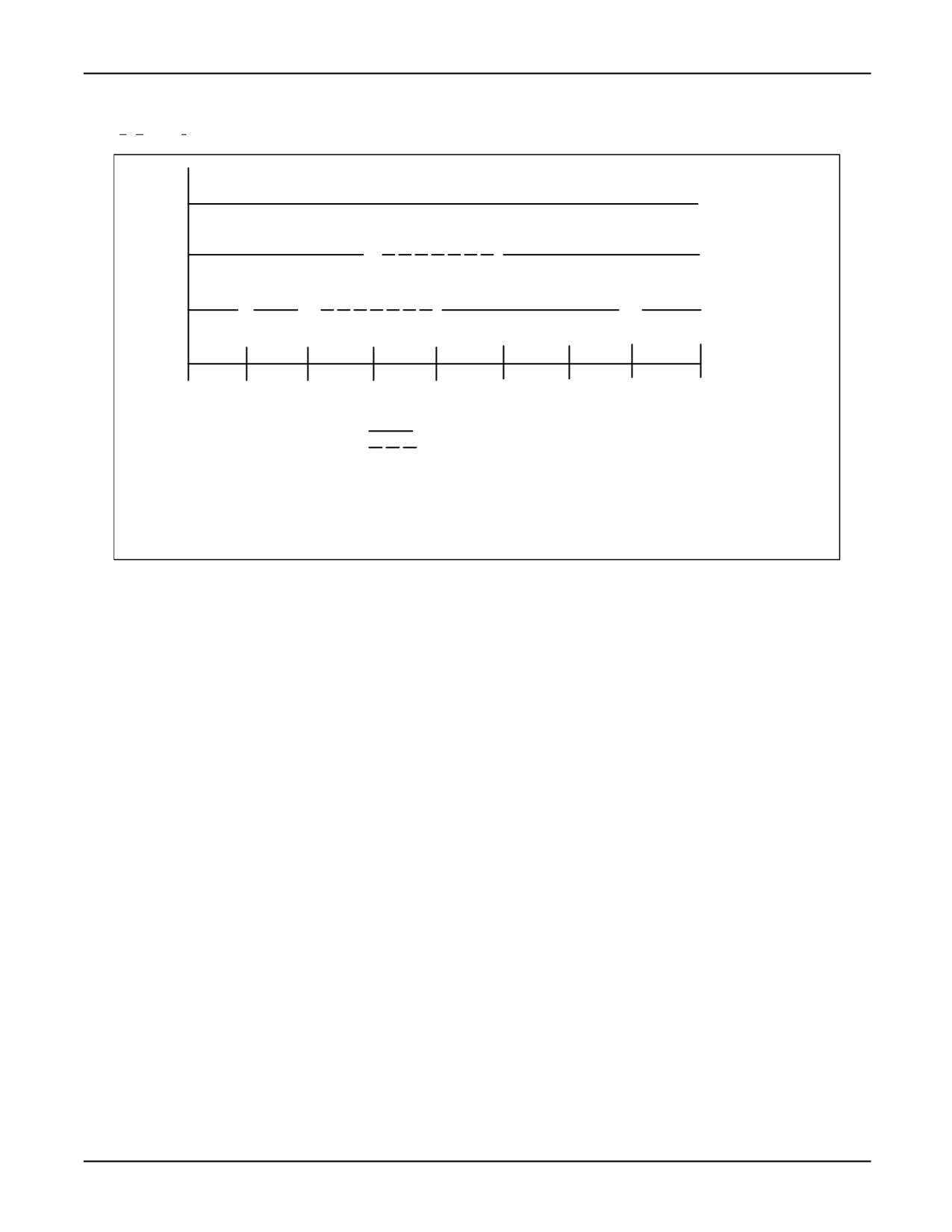
Post to a semaphore (KAREL: POST_SEMA built-in): adds one to the semaphore count.
If the semaphore count is zero or greater, when the post semaphore is issued, the semaphore
count will be incremented by one. The next task waiting on the semaphore will decrement the
semaphore count and continue execution. Refer to Figure 15-1 .
If the semaphore count is negative, when the post semaphore is issued, the semaphore count will
be incremented by one. The task which has been waiting on the semaphore the longest will then
continue execution. Refer to Figure 15-1 .
•
Read a semaphore (KAREL: SEMA_COUNT built-in): returns the current semaphore count.
•
Wait for a semaphore (KAREL: PEND_SEMA built-in, SIGNAL SEMAPHORE Action):
If the semaphore count is greater than zero when the wait semaphore is issued, the semaphore
count will be decremented and the task will continue execution. Refer to Figure 15-1 .
If the semaphore count is less than or equal to zero (negative), the wait semaphore will decrement
the semaphore count and the task will wait to be released by a post semaphore. Tasks are released
on a first-in/first-out basis. For example, if task A waits on semaphore 1, then task B waits on
semaphore 1. When task D posts semaphore 1, only task A will be released. Refer to Figure 15-1 .
15-9
15. MULTI-TASKING
MARRC75KR07091E Rev D
Figure 15-1. Task Synchronization Using a Semaphore
P
P
P
D
B
W
Task
A
C
W
W
T0
T1
T2
T3
T4
T5
T6
T7
Tn
W - Wait Semaphore
Task executing
T0 - semaphore count = indeterminate
P - Post Semaphore
Task waiting
T1 - semaphore count = 0
C - Clear Semaphore
T2 - semaphore count =
1
T3 - semaphore count =
2
T4 - semaphore count =
1
T5 - semaphore count = 0
T6 - semaphore count = 1
T7 - semaphore count = 0
Example: Semaphores can be used to implement a task that acts as a request server. In the
following example, the main task waits for the server to complete its operation. Semaphore[4]
is used to control access to rqst_param or R[5]. Semaphore[5] is used to signal the server task
that service is being requested; semaphore[6] is used by the server to signal that the operation is
complete.
The main task would contain the following KAREL:
Main Task
--KAREL
CLEAR_SEMA(4)
CLEAR_SEMA(5)
CLEAR_SEMA(6)
RUN TASK(‘server’,0,TRUE,TRUE,1,STATUS)
PEND_SEMA(4,max_time,time_out)
rqst_param=10
POST_SEMA(5)
PEND_SEMA(6,max_time,time_out)
The server task would contain the following KAREL code:
15-10