FANUC Robotics SYSTEM R-30iA and R-30iB Controller. KAREL Reference Manual - page 2
MARRC75KR07091E Rev D
Safety
Staying Safe During Automatic Operation
Advise all personnel who operate the robot during production to observe the following rules:
• Make sure all safety provisions are present and active.
• Know the entire workcell area. The workcell includes the robot and its work envelope, plus the
area occupied by all external devices and other equipment with which the robot interacts.
• Understand the complete task the robot is programmed to perform before initiating automatic
operation.
• Make sure all personnel are outside the work envelope before operating the robot.
• Never enter or allow others to enter the work envelope during automatic operation of the robot.
• Know the location and status of all switches, sensors, and control signals that could cause the
robot to move.
• Know where the EMERGENCY STOP buttons are located on both the robot control and external
control devices. Be prepared to press these buttons in an emergency.
• Never assume that a program is complete if the robot is not moving. The robot could be waiting
for an input signal that will permit it to continue activity.
• If the robot is running in a pattern, do not assume it will continue to run in the same pattern.
• Never try to stop the robot, or break its motion, with your body. The only way to stop robot
motion immediately is to press an EMERGENCY STOP button located on the controller panel,
teach pendant, or emergency stop stations around the workcell.
Staying Safe During Inspection
When inspecting the robot, be sure to
• Turn off power at the controller.
• Lock out and tag out the power source at the controller according to the policies of your plant.
• Turn off the compressed air source and relieve the air pressure.
• If robot motion is not needed for inspecting the electrical circuits, press the EMERGENCY
STOP button on the operator panel.
• Never wear watches, rings, neckties, scarves, or loose clothing that could get caught in moving
machinery.
• If power is needed to check the robot motion or electrical circuits, be prepared to press the
EMERGENCY STOP button, in an emergency.
• Be aware that when you remove a servomotor or brake, the associated robot arm will fall if it is
not supported or resting on a hard stop. Support the arm on a solid support before you release
the brake.
xxxi
Safety
MARRC75KR07091E Rev D
Staying Safe During Maintenance
When performing maintenance on your robot system, observe the following rules:
•
Never enter the work envelope while the robot or a program is in operation.
•
Before entering the work envelope, visually inspect the workcell to make sure no potentially
hazardous conditions exist.
•
Never wear watches, rings, neckties, scarves, or loose clothing that could get caught in moving
machinery.
•
Consider all or any overlapping work envelopes of adjoining robots when standing in a work
envelope.
•
Test the teach pendant for proper operation before entering the work envelope.
•
If it is necessary for you to enter the robot work envelope while power is turned on, you must be
sure that you are in control of the robot. Be sure to take the teach pendant with you, press the
DEADMAN switch, and turn the teach pendant on. Be prepared to release the DEADMAN switch
to turn off servo power to the robot immediately.
•
Whenever possible, perform maintenance with the power turned off. Before you open the
controller front panel or enter the work envelope, turn off and lock out the 3-phase power source
at the controller.
•
Be aware that an applicator bell cup can continue to spin at a very high speed even if the robot is
idle. Use protective gloves or disable bearing air and turbine air before servicing these items.
•
Be aware that when you remove a servomotor or brake, the associated robot arm will fall if it is
not supported or resting on a hard stop. Support the arm on a solid support before you release
the brake.
Warning
Lethal voltage is present in the controller WHENEVER IT IS
CONNECTED to a power source. Be extremely careful to avoid
electrical shock. HIGH VOLTAGE IS PRESENT at the input side
whenever the controller is connected to a power source. Turning the
disconnect or circuit breaker to the OFF position removes power from
the output side of the device only.
•
Release or block all stored energy. Before working on the pneumatic system, shut off the system
air supply and purge the air lines.
•
Isolate the robot from all remote control signals. If maintenance must be done when the power
is on, make sure the person inside the work envelope has sole control of the robot. The teach
pendant must be held by this person.
xxxii
MARRC75KR07091E Rev D
Safety
• Make sure personnel cannot get trapped between the moving robot and other equipment. Know the
path that can be used to escape from a moving robot. Make sure the escape route is never blocked.
• Use blocks, mechanical stops, and pins to prevent hazardous movement by the robot. Make sure
that such devices do not create pinch points that could trap personnel.
Warning
Do not try to remove any mechanical component from the robot
before thoroughly reading and understanding the procedures in the
appropriate manual. Doing so can result in serious personal injury and
component destruction.
• Be aware that when you remove a servomotor or brake, the associated robot arm will fall if it is
not supported or resting on a hard stop. Support the arm on a solid support before you release
the brake.
• When replacing or installing components, make sure dirt and debris do not enter the system.
• Use only specified parts for replacement. To avoid fires and damage to parts in the controller,
never use nonspecified fuses.
• Before restarting a robot, make sure no one is inside the work envelope; be sure that the robot and
all external devices are operating normally.
KEEPING MACHINE TOOLS AND EXTERNAL DEVICES SAFE
Certain programming and mechanical measures are useful in keeping the machine tools and other
external devices safe. Some of these measures are outlined below. Make sure you know all associated
measures for safe use of such devices.
Programming Safety Precautions
Implement the following programming safety measures to prevent damage to machine tools and
other external devices.
• Back-check limit switches in the workcell to make sure they do not fail.
• Implement “failure routines” in programs that will provide appropriate robot actions if an external
device or another robot in the workcell fails.
• Use handshaking protocol to synchronize robot and external device operations.
• Program the robot to check the condition of all external devices during an operating cycle.
xxxiii
Safety
MARRC75KR07091E Rev D
Mechanical Safety Precautions
Implement the following mechanical safety measures to prevent damage to machine tools and other
external devices.
• Make sure the workcell is clean and free of oil, water, and debris.
• Use DCS (Dual Check Safety), software limits, limit switches, and mechanical hardstops to
prevent undesired movement of the robot into the work area of machine tools and external devices.
KEEPING THE ROBOT SAFE
Observe the following operating and programming guidelines to prevent damage to the robot.
Operating Safety Precautions
The following measures are designed to prevent damage to the robot during operation.
• Use a low override speed to increase your control over the robot when jogging the robot.
• Visualize the movement the robot will make before you press the jog keys on the teach pendant.
• Make sure the work envelope is clean and free of oil, water, or debris.
• Use circuit breakers to guard against electrical overload.
Programming Safety Precautions
The following safety measures are designed to prevent damage to the robot during programming:
• Establish interference zones to prevent collisions when two or more robots share a work area.
• Make sure that the program ends with the robot near or at the home position.
• Be aware of signals or other operations that could trigger operation of tooling resulting in personal
injury or equipment damage.
• In dispensing applications, be aware of all safety guidelines with respect to the dispensing
materials.
Note Any deviation from the methods and safety practices described in this manual must conform
to the approved standards of your company. If you have questions, see your supervisor.
xxxiv
MARRC75KR07091E Rev D
Safety
ADDITIONAL SAFETY CONSIDERATIONS FOR PAINT ROBOT
INSTALLATIONS
Process technicians are sometimes required to enter the paint booth, for example, during daily or
routine calibration or while teaching new paths to a robot. Maintenance personal also must work
inside the paint booth periodically.
Whenever personnel are working inside the paint booth, ventilation equipment must be used.
Instruction on the proper use of ventilating equipment usually is provided by the paint shop supervisor.
Although paint booth hazards have been minimized, potential dangers still exist. Therefore, today’s
highly automated paint booth requires that process and maintenance personnel have full awareness of
the system and its capabilities. They must understand the interaction that occurs between the vehicle
moving along the conveyor and the robot(s), hood/deck and door opening devices, and high-voltage
electrostatic tools.
Caution
Ensure that all ground cables remain connected. Never operate the paint robot
with ground provisions disconnected. Otherwise, you could injure personnel or
damage equipment.
Paint robots are operated in three modes:
• Teach or manual mode
• Automatic mode, including automatic and exercise operation
• Diagnostic mode
During both teach and automatic modes, the robots in the paint booth will follow a predetermined
pattern of movements. In teach mode, the process technician teaches (programs) paint paths using
the teach pendant.
In automatic mode, robot operation is initiated at the System Operator Console (SOC) or Manual
Control Panel (MCP), if available, and can be monitored from outside the paint booth. All personnel
must remain outside of the booth or in a designated safe area within the booth whenever automatic
mode is initiated at the SOC or MCP.
In automatic mode, the robots will execute the path movements they were taught during teach mode,
but generally at production speeds.
xxxv
Safety
MARRC75KR07091E Rev D
When process and maintenance personnel run diagnostic routines that require them to remain in the
paint booth, they must stay in a designated safe area.
Paint System Safety Features
Process technicians and maintenance personnel must become totally familiar with the equipment and
its capabilities. To minimize the risk of injury when working near robots and related equipment,
personnel must comply strictly with the procedures in the manuals.
This section provides information about the safety features that are included in the paint system and
also explains the way the robot interacts with other equipment in the system.
The paint system includes the following safety features:
•
Most paint booths have red warning beacons that illuminate when the robots are armed and ready
to paint. Your booth might have other kinds of indicators. Learn what these are.
•
Some paint booths have a blue beacon that, when illuminated, indicates that the electrostatic
devices are enabled. Your booth might have other kinds of indicators. Learn what these are.
•
EMERGENCY STOP buttons are located on the robot controller and teach pendant. Become
familiar with the locations of all E-STOP buttons.
•
An intrinsically safe teach pendant is used when teaching in hazardous paint atmospheres.
•
A DEADMAN switch is located on each teach pendant. When this switch is held in, and the teach
pendant is on, power is applied to the robot servo system. If the engaged DEADMAN switch
is released during robot operation, power is removed from the servo system, all axis brakes are
applied, and the robot comes to an EMERGENCY STOP. Safety interlocks within the system
might also E-STOP other robots.
Warning
An EMERGENCY STOP will occur if the DEADMAN switch is released
on a bypassed robot.
•
Overtravel by robot axes is prevented by software limits. All of the major and minor axes are
governed by software limits. DCS (Dual Check Safety), limit switches and hardstops also limit
travel by the major axes.
•
EMERGENCY STOP limit switches and photoelectric eyes might be part of your system.
Limit switches, located on the entrance/exit doors of each booth, will EMERGENCY STOP all
equipment in the booth if a door is opened while the system is operating in automatic or manual
mode. For some systems, signals to these switches are inactive when the switch on the SOC is
xxxvi

MARRC75KR07091E Rev D
Safety
in teach mode.When present, photoelectric eyes are sometimes used to monitor unauthorized
intrusion through the entrance/exit silhouette openings.
• System status is monitored by computer. Severe conditions result in automatic system shutdown.
Staying Safe While Operating the Paint Robot
When you work in or near the paint booth, observe the following rules, in addition to all rules for
safe operation that apply to all robot systems.
Warning
Observe all safety rules and guidelines to avoid injury.
Warning
Never bypass, strap, or otherwise deactivate a safety device, such as a
limit switch, for any operational convenience. Deactivating a safety device
is known to have resulted in serious injury and death.
Warning
Enclosures shall not be opened unless the area is known to be
nonhazardous or all power has been removed from devices within the
enclosure. Power shall not be restored after the enclosure has been
opened until all combustible dusts have been removed from the interior
of the enclosure and the enclosure purged. Refer to the Purge chapter
for the required purge time.
•
Know the work area of the entire paint station (workcell).
•
Know the work envelope of the robot and hood/deck and door opening devices.
•
Be aware of overlapping work envelopes of adjacent robots.
•
Know where all red, mushroom-shaped EMERGENCY STOP buttons are located.
•
Know the location and status of all switches, sensors, and/or control signals that might cause the
robot, conveyor, and opening devices to move.
•
Make sure that the work area near the robot is clean and free of water, oil, and debris. Report
unsafe conditions to your supervisor.
•
Become familiar with the complete task the robot will perform BEFORE starting automatic mode.
xxxvii
Safety
MARRC75KR07091E Rev D
• Make sure all personnel are outside the paint booth before you turn on power to the robot servo
system.
• Never enter the work envelope or paint booth before you turn off power to the robot servo system.
• Never enter the work envelope during automatic operation unless a safe area has been designated.
• Never wear watches, rings, neckties, scarves, or loose clothing that could get caught in moving
machinery.
• Remove all metallic objects, such as rings, watches, and belts, before entering a booth when the
electrostatic devices are enabled.
• Stay out of areas where you might get trapped between a moving robot, conveyor, or opening
device and another object.
• Be aware of signals and/or operations that could result in the triggering of guns or bells.
• Be aware of all safety precautions when dispensing of paint is required.
• Follow the procedures described in this manual.
Special Precautions for Combustible Dusts (powder paint)
When the robot is used in a location where combustible dusts are found, such as the application of
powder paint, the following special precautions are required to insure that there are no combustible
dusts inside the robot.
• Purge maintenance air should be maintained at all times, even when the robot power is off. This
will insure that dust can not enter the robot.
• A purge cycle will not remove accumulated dusts. Therefore, if the robot is exposed to dust
when maintenance air is not present, it will be necessary to remove the covers and clean out any
accumulated dust. Do not energize the robot until you have performed the following steps.
1. Before covers are removed, the exterior of the robot should be cleaned to remove accumulated
dust.
2. When cleaning and removing accumulated dust, either on the outside or inside of the robot, be
sure to use methods appropriate for the type of dust that exists. Usually lint free rags dampened
with water are acceptable. Do not use a vacuum cleaner to remove dust as it can generate static
electricity and cause an explosion unless special precautions are taken.
3. Thoroughly clean the interior of the robot with a lint free rag to remove any accumulated dust.
4. When the dust has been removed, the covers must be replaced immediately.
5. Immediately after the covers are replaced, run a complete purge cycle. The robot can now
be energized.
xxxviii
MARRC75KR07091E Rev D
Safety
Staying Safe While Operating Paint Application Equipment
When you work with paint application equipment, observe the following rules, in addition to all rules
for safe operation that apply to all robot systems.
Warning
When working with electrostatic paint equipment, follow all national and
local codes as well as all safety guidelines within your organization.
Also reference the following standards: NFPA 33 Standards for Spray
Application Using Flammable or Combustible Materials , and NFPA 70
National Electrical Code .
•
Grounding: All electrically conductive objects in the spray area must be grounded. This includes
the spray booth, robots, conveyors, workstations, part carriers, hooks, paint pressure pots, as well
as solvent containers. Grounding is defined as the object or objects shall be electrically connected
to ground with a resistance of not more than 1 megohms.
•
High Voltage: High voltage should only be on during actual spray operations. Voltage should be
off when the painting process is completed. Never leave high voltage on during a cap cleaning
process.
•
Avoid any accumulation of combustible vapors or coating matter.
•
Follow all manufacturer recommended cleaning procedures.
•
Make sure all interlocks are operational.
•
No smoking.
•
Post all warning signs regarding the electrostatic equipment and operation of electrostatic
equipment according to NFPA 33 Standard for Spray Application Using Flammable or
Combustible Material.
•
Disable all air and paint pressure to bell.
•
Verify that the lines are not under pressure.
Staying Safe During Maintenance
When you perform maintenance on the painter system, observe the following rules, and all other
maintenance safety rules that apply to all robot installations. Only qualified, trained service or
maintenance personnel should perform repair work on a robot.
• Paint robots operate in a potentially explosive environment. Use caution when working with
electric tools.
• When a maintenance technician is repairing or adjusting a robot, the work area is under the control
of that technician. All personnel not participating in the maintenance must stay out of the area.
xxxix
Safety
MARRC75KR07091E Rev D
•
For some maintenance procedures, station a second person at the control panel within reach
of the EMERGENCY STOP button. This person must understand the robot and associated
potential hazards.
•
Be sure all covers and inspection plates are in good repair and in place.
•
Always return the robot to the ‘‘home’’ position before you disarm it.
•
Never use machine power to aid in removing any component from the robot.
•
During robot operations, be aware of the robot’s movements. Excess vibration, unusual sounds,
and so forth, can alert you to potential problems.
•
Whenever possible, turn off the main electrical disconnect before you clean the robot.
•
When using vinyl resin observe the following:
— Wear eye protection and protective gloves during application and removal
— Adequate ventilation is required. Overexposure could cause drowsiness or skin and eye
irritation.
— If there is contact with the skin, wash with water.
— Follow the Original Equipment Manufacturer’s Material Safety Data Sheets.
•
When using paint remover observe the following:
— Eye protection, protective rubber gloves, boots, and apron are required during booth cleaning.
— Adequate ventilation is required. Overexposure could cause drowsiness.
— If there is contact with the skin or eyes, rinse with water for at least 15 minutes. Then, seek
medical attention as soon as possible.
— Follow the Original Equipment Manufacturer’s Material Safety Data Sheets.
xl
Chapter 1
KAREL LANGUAGE OVERVIEW
Contents
Chapter 1
KAREL LANGUAGE OVERVIEW
1-1
1.1
OVERVIEW
1-2
1.2
KAREL PROGRAMMING LANGUAGE
1-2
1.2.1
Overview
1-2
1.2.2
Creating a Program
1-4
1.2.3
Translating a Program
1-4
1.2.4
Loading Program Logic and Data
1-4
1.2.5
Executing a Program
1-5
1.2.6
Execution History
1-5
1.2.7
Program Structure
1-5
1.3
SYSTEM SOFTWARE
1-7
1.3.1
Software Components
1-7
1.3.2
Supported Robots
1-7
1.4
CONTROLLER
1-8
1.4.1
Memory
1-8
1.4.2
Input/Output System
1-10
1.4.3
User Interface Devices
1-10
1-1
1. KAREL LANGUAGE OVERVIEW
MARRC75KR07091E Rev D
1.1
OVERVIEW
FANUC Robotics’ KAREL system consists of a robot, a controller and system software. It
accomplishes industrial tasks using programs written in the KAREL programming language. KAREL
can manipulate data, control and communicate with related equipment and interact with an operator.
The SYSTEM R-30iA controller with KAREL works with a wide range of robot models to handle
a variety of applications. This means common operating, programming, and troubleshooting
procedures, as well as fewer spare parts. KAREL systems expand to include a full line of support
products such as integral vision, off-line programming, and application-specific software packages.
The KAREL programming language is a practical blend of the logical, English-like features of
high-level languages, such as Pascal and PL/1, and the proven factory-floor effectiveness of machine
control languages. KAREL incorporates structures and conventions common to high-level languages
as well as features developed especially for robotics applications. These KAREL features include
• Simple and structured data types
• Arithmetic, relational, and Boolean operators
• Control structures for loops and selections
• Condition handlers
• Procedure and function routines
• Input and output operations
• Multi-programming support
This chapter summarizes the KAREL programming language, and describes the KAREL system
software and the controller.
The following note applies to R-30iB controllers:
Note The KAREL option must be installed on the robot controller in order to load KAREL
programs.
1.2
KAREL PROGRAMMING LANGUAGE
1.2.1
Overview
A KAREL program is made up of declarations and executable statements stored in a source code file.
The variable data values associated with a program are stored in a variable file.
1-2
MARRC75KR07091E Rev D
1. KAREL LANGUAGE OVERVIEW
KAREL programs are created and edited using OLPC PRO, or another editor such as Word Pad.
The KAREL language translator turns the source code into an internal format called p-code and
generates a p-code file. The translator is provided with OLPC PRO. After being translated, the
resulting p-code program can be loaded onto the controller using the KAREL Command Language
(KCL) or the FILE menu.
During loading, the system will create any required variables that are not in RAM and set them
uninitialized. When you run the program, the KAREL interpreter executes the loaded p-code
instructions.
A KAREL program is composed of the program logic and the program data. Program logic defines a
sequence of steps to be taken to perform a specific task. Program data is the task-related information
that the program logic uses. In KAREL the program logic is separate from the program data.
Program logic is defined by KAREL executable statements between the BEGIN and the END
statements in a KAREL program. Program data includes variables that are identified in the VAR
declaration section of a KAREL program by name, data type and storage area in RAM.
Values for program data can be taught using the teach pendant to jog the robot, computed by the
program, read from data files, set from within the CRT/KB or teach pendant menu structure, or
accepted as input to the program during execution. The data values can change from one execution to
the next, but the same program logic is used to manipulate the data.
Program logic and program data are separate in a KAREL program for the following reasons:
• To allow data to be referenced from several places in the same program
• To allow more than one program to reference or share the same data
• To allow a program to use alternative data
• To facilitate the building of data files by an off-line computer-aided design (CAD) system
The executable section of the program contains the data manipulation statements, I/O statements,
and routine calls.
The program development cycle is described briefly in the following list. Section 1.2.2 - Section
1.2.6 that follow provide details on each phase.
• Create a program source code file
• Translate the program file.
• Load the program logic and data.
• Execute the program.
• Maintain the execution history of the program.
A log or history of programs that have been executed is maintained by the controller and can be
viewed.
1-3
1. KAREL LANGUAGE OVERVIEW
MARRC75KR07091E Rev D
1.2.2
Creating a Program
You can create a KAREL program using an off-line editor such as OLPC PRO or any text editor such
as WordPad. The resulting file is called the source file or source code.
1.2.3
Translating a Program
KAREL source files must be translated into internal code, called p-code, before they are executed.
The KAREL language translator performs this function and also checks for errors in the source code.
The KAREL language translator starts at the first line of the source code and continues until it
encounters an error or translates the program successfully. If an error is encountered, the translator
tries to continue checking the program, but no p-code will be generated.
You can invoke the translator from OLPC PRO, and the source code you were editing will be
translated. After a successful translation, the translator displays a successful translation message and
creates a p-code file. The p-code file will use the source code file name and a .pc file type. This file
contains an internal representation of the source code and information the system needs to link the
program to variable data and routines.
If the translator detects any errors, it displays the error messages and the source lines that were being
translated. After you have corrected the errors, you can translate the program again.
1.2.4
Loading Program Logic and Data
The following note applies to R-30iB controllers:
Note The KAREL option must be installed on the robot controller in order to load KAREL
programs.
The p-code for a program is loaded onto a controller where it can be executed. When a program is
loaded, a variable data table, containing all the static variables in the program, is created in RAM. The
variable data table contains the program identifier, all of the variable identifiers, and the name of the
storage area in RAM where the variables are located.
Loading a program also establishes the links between statements and variables. Initially, the values in
the variable data table will be uninitialized. If a variable file (.vr) is loaded successfully, the values of
any variables will be stored in the variable data storage area (CMOS, DRAM, SHADOW).
1-4
MARRC75KR07091E Rev D
1. KAREL LANGUAGE OVERVIEW
Multiple programs are often used to break a large application or problem into smaller pieces that can
be developed and tested separately. The KAREL system permits loading of multiple programs. Each
program that is loaded has its own p-code structure.
Variable data can be shared among multiple programs. In this case, the KAREL language FROM
clause must be specified in the VAR declaration so that the system can perform the link when the
program is loaded. This saves the storage required to include multiple copies of the data.
The following limits apply to the number and size of KAREL programs that can be loaded:
• Number of programs is limited to 2704 or available RAM.
• Number of variables per program is limited to 2704 or available RAM.
1.2.5
Executing a Program
After you have selected a program from the program list and the p-code and variable files are loaded
into RAM, test and debug the program to make sure that it operates as intended.
Program execution begins at the first executable line. A stack of 300 words is allocated unless you
specify a stack size. The stack is allocated from available user RAM. Stack usage is described
in Section 5.1.6 .
1.2.6
Execution History
Each time a program is executed, a log of the nested routines and the line numbers that have been
executed can be displayed from KCL with the SHOW HISTORY command.
This is useful when a program has paused or been aborted unexpectedly. Execution history displays
the sequence of events that led to the disruption.
1.2.7
Program Structure
A KAREL program is composed of declaration and executable sections made up of KAREL language
statements, as shown in Structure of a KAREL Program .
Structure of a KAREL Program
PROGRAM prog_name
Translator Directives
CONST, TYPE, and/or VAR Declarations
ROUTINE Declarations
BEGIN
1-5
1. KAREL LANGUAGE OVERVIEW
MARRC75KR07091E Rev D
Executable Statements
END prog_name
ROUTINE Declarations
In Structure of a KAREL Program , the words shown in uppercase letters are KAREL reserved
words, which have dedicated meanings. PROGRAM, CONST, TYPE, VAR, and ROUTINE indicate
declaration sections of the program. BEGIN and END mark the executable section. Reserved words
are described in Section 2.1.3 .
The PROGRAM statement, which identifies the program, must be the first statement in any KAREL
program. The PROGRAM statement consists of the reserved word PROGRAM and an identifier of
your choice (prog_name in Structure of a KAREL Program ). Identifiers are described in Section
2.1.4 .
Note Your program must reside in a file. The file can, but does not have to, have the same name
as the program. This distinction is important because you invoke the translator and load programs
with the name of the file containing your program, but you initiate execution of the program and clear
the program with the program name.
For example, if a program named mover was contained in a file named transfer , you would reference
the file by transfer to translate it, but would use the program name mover to execute the program.
If both the program and the file were named mover , you could use mover to translate the file and
also to execute the program.
A task is created to execute the program and the task name is the name of the program you initiate.
The program can call a routine in another program, but the task name does not change.
The identifier used to name the program cannot be used in the program for any other purpose, such
as to identify a variable or constant.
The CONST (constant), TYPE (type), and VAR (variable) declaration sections come after the
PROGRAM statement. A program can contain any number of CONST, TYPE, and VAR sections.
Each section can also contain any number of individual declaration statements. Also, multiple
CONST, TYPE, and VAR sections can appear in any order. The number of CONST, TYPE, and VAR
sections, and declaration statements are limited only by the amount of memory available.
ROUTINE declarations can follow the CONST, TYPE, and VAR sections. Each routine begins with
the reserved word ROUTINE and is similar in syntax to a program. ROUTINE declarations can also
follow the executable section of the main program after the END statement.
The executable section must be marked by BEGIN at the beginning and END, followed by the
program identifier (prog_name in Structure of a KAREL Program ), at the end. The same program
identifier must be used in the END statement as in the PROGRAM statement. The executable section
can contain any number of executable statements, limited only by the amount of memory available.
See Also: Chapter 2 LANGUAGE ELEMENTS , Chapter 3 USE OF OPERATORS , and Chapter
5 ROUTINES .
1-6
MARRC75KR07091E Rev D
1. KAREL LANGUAGE OVERVIEW
1.3
SYSTEM SOFTWARE
The R-30iA system includes a robot and controller electronics. Hardware interfaces and system
software support programming, daily operation, maintenance, and troubleshooting.
This section provides an overview of the supported system software and robot models.
Hardware topics are covered in greater detail in the Maintenance Manual specific for your robot
and controller model.
1.3.1
Software Components
R-30iA system software is the FANUC Robotics-supplied software that is executed by the controller
CPU, which allows you to operate the R-30iA system. You use the system software to run programs,
as well as to perform daily operations, maintenance, and troubleshooting.
The components of the system software include:
• Motion Control - movement of the tool center point (TCP) from an initial position to a desired
destination position
• File System - storage of data on the RAM disk or peripheral storage devices
• System Variables - permanently defined variables declared as part of the KAREL system software
• CRT/KB or Teach Pendant Screens - screens that facilitate operation of the KAREL system
• KCL - KAREL Command Language
• KAREL Interpreter - executes KAREL programs
See Also: application-specific FANUC Robotics Setup and Operations Manual for detailed operation
procedures using the CRT/KB and teach pendant screens.
1.3.2
Supported Robots
The robot, using the appropriate tooling, performs application tasks directed by the system software
and controller. The R-30iA system supports a variety of robots, each designed for a specific type of
application.
For a current list of supported robot models, consult your FANUC Robotics technical representative.
See Also: The Maintenance Manual for your specific robot type, for more information on your robot.
1-7
1. KAREL LANGUAGE OVERVIEW
MARRC75KR07091E Rev D
1.4
CONTROLLER
The R-30iA controller contains the electronic circuitry and memory required to operate the R-30iA
system. The electronic circuitry, supported by the system software, directs the operation and motion
of the robot and allows communication with peripheral devices.
Controller electronics includes a central processing unit (CPU), several types of memory, an
input/output (I/O) system, and user interface devices. A cabinet houses the controller electronics and
the ports to which remote user interface devices and other peripheral devices are connected.
1.4.1
Memory
There are three kinds of controller memory:
• Dynamic Random Access Memory (DRAM)
• A limited amount of battery-backed static/random access memory (SRAM)
• Flash Programmable Read Only Memory (FROM)
In addition, the controller is capable of storing information externally.
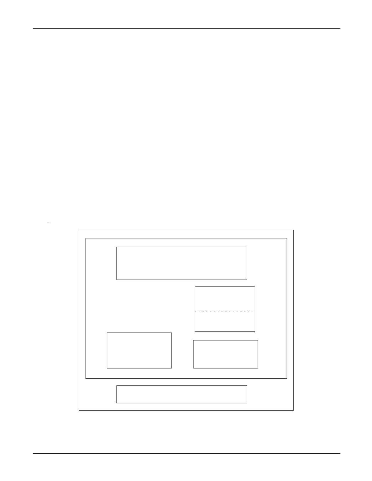
DRAM
DRAM memory is volatile. Memory contents do not retain their stored values when power is
removed. DRAM memory is also referred to as temporary memory (TEMP). The system software is
executed in DRAM memory. KAREL programs and most KAREL variables are loaded into DRAM
and executed from here also.
Note Even though DRAM variables are in volatile memory, you can control their value at startup.
Any time that a the program .VR or .PC file is loaded, the values in DRAM for that program are set to
the value in the .VR file. This means that there is not a requirement to re-load the VR file itself at
every startup to set initial values. If the value of that variable changes during normal operation it will
revert to the value it was set to the last time the .VR or .PC file was loaded.
If you want the DRAM variables to be uninitialized at start up you can use the IN UNINIT_DRAM
clause on any variable you want to insure is uninitialized at startup. You can use the %UNINITDRAM
directive to specify that all the variables in a program are to be uninitialized at startup.
If you have a SHADOW variables and DRAM variables in the same KAREL program, there is a
possibility that the power up settings of the DRAM variables could change without loading a .PC/.VR
File. In this case the programmer must pay particular attention to the reliance of KAREL software
on a particular setting of a DRAM variable at startup. Specifically, the DRAM startup values will
always retain the values that they had at the end of controlled start. If SHADOW memory is full, the
DRAM startup values could be set during normal system operation.
1-8
MARRC75KR07091E Rev D
1. KAREL LANGUAGE OVERVIEW
SRAM
SRAM memory is nonvolatile. Memory contents retain their stored values when power is removed.
SRAM memory is also referred to as CMOS or as permanent memory (PERM).
The TPP memory pool (used for teach pendant programs) is allocated from PERM. KAREL programs
can designate variables to be stored in CMOS. A portion of SRAM memory can be defined as a
user storage device called RAM Disk (RD:).
Flash memory (FROM)
FROM memory is nonvolatile. Memory contents retain their stored values when power is removed.
FROM is used for permanent storage of the system software. FROM is also available for user storage
as the FROM device (FR:).
SHADOW
Shadow memory provides the same capabilities as SRAM. Any values set in shadow are non-volatile
and will maintain their state through power cycle. Shadow memory is intended for data which tends to
be static. Storing dynamic variables in shadow memory, such as FOR loop indexes or other rapidly
changing data, is not efficient.
Figure 1-1. Controller Memory
DRAM
(TEMP)
Working memory for the system
Loaded KAREL programs
Most KAREL variables
CMOS RAM
(PERM)
Loaded TP Programs
System Variables
Selected KAREL Variables
FROM Disk (FR:)
Saved Programs
RAM Disk (RD:)
Saved Data
Saved Programs
System Software
Saved Data
Off-Line Storage
Saved Programs and Data
1-9
1. KAREL LANGUAGE OVERVIEW
MARRC75KR07091E Rev D
External Storage
You can back up and store files on external devices. You can use the following devices:
• Memory card
• Ethernet via FTP
• USB Memory Stick
1.4.2
Input/Output System
The controller can support a modular I/O structure, allowing you to add I/O boards as required by
your application. Both digital and analog input and output modules are supported. In addition, you
can add optional process I/O boards for additional I/O. The type and number of I/O signals you have
depends on the requirements of your application.
See Also: Chapter 14 INPUT/OUTPUT SYSTEM , for more information
1.4.3
User Interface Devices
The user interface devices enable you to program and operate the KAREL system. The common user
interface devices supported by KAREL include the operator panel, the teach pendant or the CRT/KB.
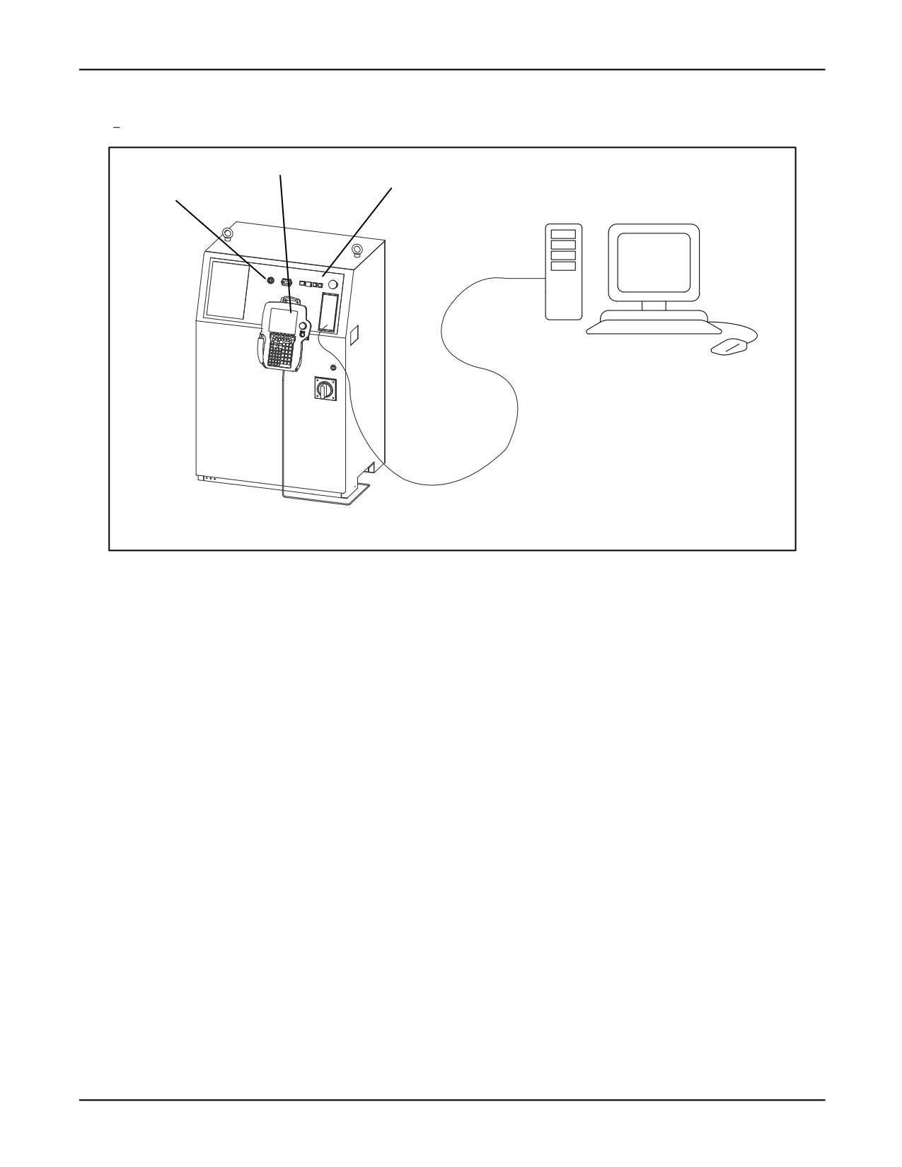
Figure 1-2 illustrates these user interface devices. The operator panel and teach pendant have the
same basic functions for all models; however, different configurations are also available.
The operator panel, located on the front of the controller cabinet, provides buttons for performing
daily operations such as powering up, running a program, and powering down. Lights on the operator
panel indicate operating conditions such as when the power is on and when the robot is in cycle.
The system also supports I/O signals for a user operator panel (UOP) , which is a user-supplied
device such as a custom control panel, a programmable controller, or a host computer. Refer to
Chapter 14 INPUT/OUTPUT SYSTEM .
1-10
MARRC75KR07091E Rev D
1. KAREL LANGUAGE OVERVIEW
Figure 1-2. R-30iA Controller
Teach pendant
Operator panel
Mode switch
RS-232 Serial Connection
The CRT/KB is a software option on the controller that allows an external terminal such as a PC
running TelNet to display a Menu System that looks similar to the one seen on the teach pendant.
The teach pendant consists of an LCD display, menu-driven function keys, keypad keys, and status
LEDs. It is connected to the controller cabinet via a cable, allowing you to perform operations away
from the controller.
Internally, the teach pendant connects to the controller’s Main CPU board. It is used to jog the robot,
teach program data, test and debug programs, and adjust variables. It can also be used to monitor and
control I/O, to control end-of-arm tooling, and to display information such as the current position of
the robot or the status of an application program.
The application-specific FANUC Robotics Setup and Operations Manual provides descriptions of
each of the user interface devices, as well as procedures for operating each device.
1-11
Chapter 2
LANGUAGE ELEMENTS
Contents
Chapter 2
LANGUAGE ELEMENTS
2-1
2.1
LANGUAGE COMPONENTS
2-2
2.1.1
Character Set
2-2
2.1.2
Operators
2-5
2.1.3
Reserved Words
2-6
2.1.4
User-Defined Identifiers
2-7
2.1.5
Labels
2-8
2.1.6
Predefined Identifiers
2-8
2.1.7
System Variables
2-10
2.1.8
Comments
2-10
2.2
TRANSLATOR DIRECTIVES
2-11
2.3
DATA TYPES
2-13
2.4
USER-DEFINED DATA TYPES AND STRUCTURES
2-14
2.4.1
User-Defined Data Types
2-14
2.4.2
User-Defined Data Structures
2-16
2.5
ARRAYS
2-18
2.5.1
Multi-Dimensional Arrays
2-19
2.5.2
Variable-Sized Arrays
2-20
2-1
2. LANGUAGE ELEMENTS
MARRC75KR07091E Rev D
The KAREL language provides the elements necessary for programming effective robotics
applications. This chapter lists and describes each of the components of the KAREL language, the
available translator directives and the available data types.
2.1
LANGUAGE COMPONENTS
This section describes the following basic components of the KAREL language:
• Character set
• Operators
• Reserved words
• User-defined Identifiers
• Labels
• Predefined Identifiers
• System Variables
• Comments
2.1.1
Character Set
The ASCII character set is available in the KAREL language. Table 2-1 lists the elements in the
ASCII character set. Three character sets are available in the KAREL language:
• ASCII Character Set
• Multinational Character Set
• Graphics Character Set (not available in R-30iB)
All of the characters recognized by the KAREL language are listed in Table 2-1 , Table 2-2 , and
Table 2-3 . The default character set is ASCII. The multinational and graphics character sets are
permitted only in literals, data, and comments.
See Also: CHR Built-In Procedure, Appendix A .
Table 2-1. ASCII Character Set
Letters
abcdefghijklmnopqrstuvwxyz
ABCDEFGHIJKLMNOPQRSTUVWXYZ
Digits
012 3 45 67 8 9
2-2
MARRC75KR07091E Rev D
2. LANGUAGE ELEMENTS
Table 2-1. ASCII Character Set (Cont’d)
Symbols
@<>=/*+-_,;: . #$’[]()&%{}
Special Characters
blank or space
form feed (treated as new line)
tab (treated as a blank space)
The following rules are applicable for the ASCII character set:
• Blanks or spaces are:
— Required to separate reserved words and identifiers. For example, the statement PROGRAM
prog_name must include a blank between PROGRAM and prog_name .
— Allowed but are not required within expressions between symbolic operators and their
operands. For example, the statement a = b is equivalent to a=b .
— Used to indent lines in a program.
• Carriage return or a semi-colon (;) separate statements. Carriage returns can also appear in
other places.
• A carriage return or a semi-colon is required after the BEGIN statement.
• A line is truncated after 252 characters. It can be continued on the next line by using the
concatenation character &.
2-3
2. LANGUAGE ELEMENTS
MARRC75KR07091E Rev D
Table 2-2. Multinational Character Set
Symbols
¡
¢
£
¥
§
¤
2
a
«
Ɉ
±
3
1
µ
¶
•
o
»
¼
½
¿
Special Characters
À
Á
Â
Ã
Ä
Å
Æ
Ç
È
É
Ê
Ë
Ì
Í
Î
Ï
Ñ
Ò
Ó
Ô
Õ
Ö
Œ
Ø
Ù
Ú
Û
Ü
Y
ß
à
á
â
ã
ä
å
æ
ç
è
é
ê
ë
ì
í
î
ï
ñ
ò
ó
ô
õ
ö
œ
ø
ù
ú
û
ü
ÿ
2-4
MARRC75KR07091E Rev D
2. LANGUAGE ELEMENTS
Table 2-3. Graphics Character Set
Letters
A B C D E F G H I J K L MN O P Q R S T U V W X Y Z
Digits
01 23456789
Symbols
@<>=/*+-,; : . #$’\[]()&%! "^
H
F
C
L
N
V
Special
♦
Ɉ
±
┘
┐
┌
└
F
R
F
L
T
Characters
T
-
-
+
-
-
_
├
┤
┴
┬
|
Ȇ
£
See Also: Appendix D for a listing of the character codes for each character set
2.1.2
Operators
KAREL provides operators for standard arithmetic operations, relational operations, and Boolean
(logical) operations. KAREL also includes special operators that can be used with positional and
VECTOR data types as operands.
Table 2-4 lists all of the operators available for use with KAREL.
Table 2-4.
KAREL Operators
Arithmetic
+
-
/
DIV
MOD
Relational
<
<=
=
<>
>=
>
Boolean
AND
OR
NOT
Special
>=<
:
#
@
The precedence rules for these operators are as follows:
• Expressions within parentheses are evaluated first.
• Within a given level of parentheses, operations are performed starting with those of highest
precedence and proceeding to those of lowest precedence.
• Within the same level of parentheses and operator precedence, operations are performed from
left to right.
Table 2-5 lists the precedence levels for the KAREL operators.
2-5
2. LANGUAGE ELEMENTS
MARRC75KR07091E Rev D
Table 2-5. KAREL Operator Precedence
OPERATOR
PRECEDENCE LEVEL
NOT
High
:, @, #
Ļ
*, /, AND, DIV, MOD
Ļ
Unary + and -, OR, +, -
Ļ
<, >, =, < >, < =, > =, > = <
Low
See Also: Chapter 3 USE OF OPERATORS , for descriptions of functions operators perform
2.1.3
Reserved Words
Reserved words have a dedicated meaning in KAREL. They can be used only in their prescribed
contexts. All KAREL reserved words are listed in Table
2-6 .
Table 2-6. Reserved Word List
ABORT
CONST
GET_VAR
NOPAUSE
STOP
ABOUT
CONTINUE
GO
NOT
STRING
ABS
COORDINATED
GOTO
NOWAIT
STRUCTURE
AFTER
CR
GROUP
OF
THEN
ALONG
DELAY
GROUP_ASSOC
OPEN
TIME
ALSO
DISABLE
HAND
OR
TIMER
AND
DISCONNECT
HOLD
PATH
TO
ARRAY
DIV
IF
PATHHEADER
TPENABLE
ARRAY_LEN
DO
IN
PAUSE
TYPE
AT
DOWNTO
INDEPENDENT
POSITION
UNHOLD
ATTACH
DRAM
INTEGER
POWERUP
UNINIT
AWAY
ELSE
JOINTPOS
PROGRAM
UNPAUSE
AXIS
ENABLE
JOINTPOS1
PULSE
UNTIL
BEFORE
END
JOINTPOS2
PURGE
USING
BEGIN
ENDCONDITION
JOINTPOS3
READ
VAR
BOOLEAN
ENDFOR
JOINTPOS4
REAL
VECTOR
BY
ENDIF
JOINTPOS5
RELATIVE
VIA
2-6
MARRC75KR07091E Rev D
2. LANGUAGE ELEMENTS
Table 2-6. Reserved Word List (Cont’d)
BYNAME
ENDMOVE
JOINTPOS6
RELAX
VIS_PROCESS
BYTE
ENDSELECT
JOINTPOS7
RELEASE
WAIT
CAM_SETUP
ENDSTRUCTURE
JOINTPOS8
REPEAT
WHEN
CANCEL
ENDUSING
JOINTPOS9
RESTORE
WHILE
CASE
ENDWHILE
MOD
RESUME
WITH
CLOSE
ERROR
MODEL
RETURN
WRITE
CMOS
EVAL
MOVE
ROUTINE
XYZWPR
COMMAND
EVENT
NEAR
SELECT
XYZWPREXT
COMMON_ASSOC
END
NOABORT
SEMAPHORE
CONDITION
FILE
NODE
SET_VAR
CONFIG
FOR
NODEDATA
SHORT
CONNECT
FROM
NOMESSAGE
SIGNAL
See Also: Index for references to descriptions of KAREL reserved words
2.1.4
User-Defined Identifiers
User-defined identifiers represent constants, data types, statement labels, variables, routine names,
and program names. Identifiers
• Start with a letter
• Can include letters, digits, and underscores
• Can have a maximum of 12 characters
• Can have only one meaning within a particular scope. Refer to Section 5.1.4 .
• Cannot be reserved words
• Must be defined before they can be used.
For example, the program excerpt in Declaring Identifiers shows how to declare program, variable,
and constant identifiers.
Declaring Identifiers
PROGRAM mover
--program identifier (mover)
VAR
original
: POSITION
--variable identifier (original)
CONST
2-7
2. LANGUAGE ELEMENTS
MARRC75KR07091E Rev D
no_of_parts = 10
--constant identifier (no_of_parts)
2.1.5
Labels
Labels are special identifiers that mark places in the program to which program control can be
transferred using the GOTO Statement.
• Are immediately followed by two colons (::). Executable statements are permitted on the same
line and subsequent lines following the two colons.
• Cannot be used to transfer control into or out of a routine.
In Using Labels , weld: : denotes the section of the program in which a part is welded. When the
statement go to weld is executed, program control is transferred to the weld section.
Using Labels
weld::
--label
--additional program statements
GOTO weld
2.1.6
Predefined Identifiers
Predefined identifiers within the KAREL language have a predefined meaning. These can be
constants, types, variables, or built-in routine names. Table 2-7 and Table 2-8 list the predefined
identifiers along with their corresponding values. Either the identifier or the value can be specified in
the program statement. For example, $MOTYPE = 7 is the same as $MOTYPE = LINEAR. However,
the predefined identifier MININT is an exception to this rule. This identifier must always be used in
place of its value, -2147483648. The value or number itself can not be used.
Table 2-7. Predefined Identifier and Value Summary
Predefined Identifier
Type
Value
TRUE
BOOLEAN
ON
FALSE
OFF
ON
BOOLEAN
ON
OFF
OFF
MAXINT
INTEGER
+2147483647
MININT
-2147483648
2-8
MARRC75KR07091E Rev D
2. LANGUAGE ELEMENTS
Table 2-7. Predefined Identifier and Value Summary (Cont’d)
Predefined Identifier
Type
Value
RSWORLD
Orientation Type:
1
AESWORLD
$ORIENT_TYPE
2
WRISTJOINT
3
JOINT
Motion Type:
6
LINEAR (or STRAIGHT)
$MOTYPE
7
CIRCULAR
8
FINE
Termination Types:
1
COARSE
$TERMTYPE and
2
NOSETTLE
$SEGTERMTYPE
3
NODECEL
4
VARDECEL
5
Table 2-8. Port and File Predefined Identifier Summary
Predefined Identifier
Type
DIN (Digital input)
Boolean port array
DOUT (Digital output)
GIN (Group input)
Integer port array
GOUT (Group output)
AIN (Analog input)
AOUT (Analog output)
TPIN (Teach pendant input)
Boolean port array
TPOUT (Teach pendant output)
RDI (Robot digital input)
RDO (Robot digital output)
OPIN (Operator panel input)
OPOUT (Operator panel output)
WDI (Weld input)
WDOUT (Weld output)
UIN (User operator panel input)
UOUT (User operator panel output)
LDI (Laser digital input)
LDO (Laser digital output)
FLG (Flag)
MRK (Marker)
2-9
2. LANGUAGE ELEMENTS
MARRC75KR07091E Rev D
Table 2-8. Port and File Predefined Identifier Summary (Cont’d)
Predefined Identifier
Type
LAI (Laser analog input)
Integer port array
LAO (Laser analog output)
TPDISPLAY (Teach pendant KAREL display)*
File
TPERROR (Teach pendant message line)
TPPROMPT (Teach pendant function key line)*
TPFUNC (Teach pendant function key line)*
TPSTATUS (Teach pendant status line)*
INPUT (CRT/KB KAREL keyboard)*
OUTPUT (CRT/KB KAREL screen)*
CRTERROR (CRT/KB message line)
CRTFUNC (CRT function key line)*
CRTSTATUS (CRT status line)*
CRTPROMPT (CRT prompt line)*
VIS_MONITOR (Vision Monitor Screen)
*Input and output occurs on the USER menu of the teach pendant or CRT/KB.
2.1.7
System Variables
System variables are variables that are declared as part of the KAREL system software. They have
permanently defined variable names, that begin with a dollar sign ($). Many are robot specific,
meaning their values depend on the type of robot that is attached to the system.
Some system variables are not accessible to KAREL programs. Access rights govern whether or not
a KAREL program can read from or write to system variables.
See Also: FANUC Robotics Software Reference Manual for a complete list and description of all
available system variables.
2.1.8
Comments
Comments are lines of text within a program used to make the program easier for you or another
programmer to understand. For example, Comments From Within a Program contains some
comments from %INCLUDE Directive in a KAREL Program and Include File mover_decs for
a KAREL Program .
Comments From Within a Program
--This program, called mover, picks up 10 objects
2-10