FANUC Series Series 16i-TB, Series 18i-TB, Series 160i-TB, Series 180i-TB. OPERATOR’S MANUAL - page 30
B-63524EN/01
APPENDIX
G. ALARM LIST
Number
Message
Contents
211
G31 (HIGH) NOT ALLOWED IN G99
G31 is commanded in the per revolution command when the high-
speed skip option is provided. Modify the program.
212
ILLEGAL PLANE SELECT
The direct drawing dimensions programming is commanded for the
plane other than the Z-X plane. Correct the program.
213
ILLEGAL COMMAND IN
Movement is commanded for the axis to be synchronously controlled.
SYNCHRO-MODE
214
ILLEGAL COMMAND IN
Coordinate system is set or tool compensation of the shift type is
SYNCHRO-MODE
executed in the synchronous control. Correct the program.
217
DUPLICATE G251 (COMMANDS)
G51.2 or G251 is further commanded in the polygon machining
mode. Modify the program.
218
NOT FOUND P/Q COMMAND IN
P or Q is not commanded in the G251 block, or the command value
G251
is out of the range. Modify the program.
219
COMMAND G250/G251
G251 and G250 are not independent blocks.
INDEPENDENTLY
220
ILLEGAL COMMAND IN
In the synchronous operation, movement is commanded by the NC
SYNCHR-MODE
program or PMC axis control interface for the synchronous axis.
221
ILLEGAL COMMAND IN
Polygon machining synchronous operation and axis control or bal-
SYNCHR-MODE
ance cutting are executed at a time. Modify the program.
224
RETURN TO REFERENCE POINT
Not returned to reference point before cycle start.
225
SYNCHRONOUS/MIXED CONTROL
This alarm is generated in the following circumstances. (Searched for
ERROR
during synchronous and mixed control command.
(only with two path control only)
1
When there is a mistake in axis number parameter setting.
2
When there is a mistake in control commanded.
Modify the program or the parameter.
226
ILLEGAL COMMAND IN
A travel command has been sent to the axis being synchronized in
SYNCHRO-MODE
synchronous mode. Modify the program or the parameter.
(only with two path control only)
229
CAN NOT KEEP SYNCHRO-STATE
This alarm is generated in the following circumstances.
(only with two path control only)
1
When the synchro/mixed state could not be kept due to system
overload.
2
The above condition occurred in CNC devices (hardware) and
synchro-state could not be kept.
(This alarm is not generated in normal use conditions.)
231
FORMAT ERROR IN G10 OR L50
Any of the following errors occurred in the specified format at the pro-
grammable-parameter input.
1
Address N or R was not entered.
2
A number not specified for a parameter was entered.
3
The axis number was too large.
4
An axis number was not specified in the axis-type parameter.
5
An axis number was specified in the parameter which is not an
axis type.
6
An attempt was made to reset bit 4 of parameter 3202 (NE9) or
change parameter 3210 (PSSWD) when they are protected by a
password. Correct the program.
232
ILLEGAL AXIS COMMAND IN
Three or more axes were specified as helical axes in the helical inter-
HELICAL
polation mode.
233
DEVICE BUSY
When an attempt was made to use a unit such as that connected via
the RS-232-C interface, other users were using it.
239
BP/S ALARM
While punching was being performed with the function for controlling
external I/O units ,background editing was performed.
855
G. ALARM LIST
APPENDIX
B-63524EN/01
Number
Message
Contents
240
BP/S ALARM
Background editing was performed during MDI operation.
244
P/S ALARM
In the skip function activated by the torque limit signal, the number of
accumulated erroneous pulses exceed 32767 before the signal was
input. Therefore, the pulses cannot be corrected with one distribution.
Change the conditions, such as federates along axes and torque
limit, and try again.
245
T-CODE NOT ALOWED IN THIS
One of the G codes, G50, G10, and G04, which cannot be specified
BLOCK
in the same block as a T code, was specified with a T code.
246
ENCODE PROGRAM NUMBER
During read of an encrypted program, an attempt was made to store
ERROR
the program with a number exceeding the protection range.
(See parameter Nos. 3222 and 3223.)
247
ILLEGAL CODE USED FOR
When an encrypted program is output, EIA is set for the punch code.
OUTPUT
Specify ISO.
5010
END OF RECORD
The end of record (%) was specified.
5014
TRACE DATA NOT FOUND
Transfer cannot be performed with servo trace function because no
trace data exists.
5016
ILLEGAL COMBINATION OF M
M codes which belonged to the same group were specified in a
CODE
block. Alternatively,an M code which must be specified without other
M codes in the block was specified in a block with other M codes.
5018
POLYGON AXIS SPPED ERROR
The rotating speed ratio of the command value cannot be maintained
in the G51.2 mode , because the spped of the spindle or the polygon
turning synchronous axis exceeds the clamp value or itis too slow.
5020
PARAMETER OF RESTART
An erroneous parameter was specified for restarting a program.
ERROR
5030
ILLEGAL COMMAND (G100)
The end command (G110) was specified before the registration start
command (G101, G102, or G103) was specified for the B-axis.
5031
ILLEGAL COMMAND (G100, G102,
While a registration start command (G101, G102, or G103) was being
G103)
executed, another registration start command was specified for the
B-axis.
5032
NEW PRG REGISTERED IN B-AXS
While the machine was moving about the B-axis, at attempt was
MOVE
made to register another move command.
5033
NO PROG SPACE IN MEMORY
Commands for movement about the B-axis were not registered be-
B-AXIS
cause of insufficient program memory.
5034
PLURAL COMMAND IN G110
Multiple movements were specified with the G110 code for the B-
axis.
5035
NO FEEDRATE COMMANDED
A feedrate was not specified for cutting feed about the B-axis.
B-AXIS
5036
ADDRESS R NOT DEFINED IN
Point R was not specified for the canned cycle for the B-axis.
G81-G86
5037
ADDRESS Q NOT DEFINED IN G83
Depth of cut Q was not specified for the G83 code (peck drilling
cycle). Alternatively, 0 was specified in Q for teh B-axis.
5038
TOO MANY START M-CODE
More than six M codes for starting movement about the B-axis were
COMMAND
specified.
5039
START UNREGISTERED B-AXIS
An attempt was made to execute a program for the B-axis which had
PROG
not been registered.
5040
CAN NOT COMMANDED B-AXIS
The machine could not move about the B-axis because parameter
MOVE
No.8250 was incorrectly specified, or because the PMC axis system
could not be used.
5041
CAN NOT COMMANDED G110
Blocks containing the G110 codes were successively specified in
BLOCK
tool-tip radius compensation for the B-axis.
5043
TOO MANY G68 NESTING
Three-dimensional coordinate conversion G68.1 has been specified
three or more times.
856
B-63524EN/01
APPENDIX
G. ALARM LIST
Number
Message
Contents
5044
G68.1 FORMAT ERROR
A G68 command block contains a format error. This alarm is issued
in the following cases:
1 I, J, or K is missing from a G68.1 command block (missing coordi-
nate rotation option).
2 I, J, and K are 0 in a G68.1 command block.
3 R is missing from a G68.1 command block.
Modify the program.
5046
ILLEGAL PARAMETER (ST.COMP)
Parameters related to straightness compensation have been erro-
neously specified. Possible causes are as follows :
1 Invalid axis numbers have been assigned to move or compensa-
tion axes.
2 The number of pitcherror compensation points between the maxi-
mum positive and maximum negative points exceeds 128.
3 Straightness compensation point numbers have been assigned in
other than ascending order.
4 Straightness compensation points could not belocated between the
maximum positive and maximum negative pitch error compensa-
tion points.
5 The amount of compensation per compensation point is too large
or too small.
5051
M-NET CODE ERROR
Abnormal character reception
(Characters except code used to transmit)
5052
M-NET ETX ERROR
“ETX” code is abnormal.
5053
M-NET CONNECT ERROR
Connection time supervision error (parameter No.175)
5054
M-NET RECEIVE ERROR
Boring time supervision error (parameter No.176)
5055
M-NET PRT/FRM ERROR
Vertical parity or framing error detection
5056
M-NET BOARD SYSTEM DOWN
Transmit time-out error (parameter No. 177)
ROM parity error
CPU interruption detection of not listed above
5058
G35/G36 FORMAT ERROR
A command for changing the major axis was specified during circular
threading. Alternatively, the leangth of the major axis was specified to
be 0.
5059
RADIUS IS OUT OF RANGE
During circular interpolation, the center of the arc specified with I, J,
and K caused the radius to exceed nine digits.
5073
NO DECIMAL POINT
A decimal point is not specified for a command for which a decimal
point must be specified.
5074
ADDRESS DUPLICATION ERROR
The same address appears more than once in a block. Alternatively,
a block contains two or more G codes belonging to the same group.
5082
DATA SERVER ERROR
Details are displayed on the data server message screen.
5134
FSSB : OPEN READY TIME OUT
Initialization did not place FSSB in the open ready state.
5135
FSSB : ERROR MODE
FSSB has entered error mode.
5136
FSSB : NUMBER OF AMPS IS
In comparison with the number of controlled axes, the number of amplifi-
SMALL
ers recognized by FSSB is not enough.
5137
FSSB : CONFIGURATION ERROR
FSSB detected a configuration error.
5138
FSSB : AXIS SETTING NOT
In automatic setting mode, axis setting has not been made yet.
COMPLETE
Perform axis setting on the FSSB setting screen.
5139
FSSB : ERROR
Servo initialization did not terminate normally.
The optical cable may be defective, or there may be an error in connec-
tion to the amplifier or another module.
Check the optical cable and the connection status.
857
G. ALARM LIST
APPENDIX
B-63524EN/01
Number
Message
Contents
5155
NOT RESTART PROGRAM BY G05
During servo leaning control by G05, an attempt was made to perform
restart operation after feed hold or interlock. This restart operation can-
not be performed. (G05 leaning control terminates at the same time.)
5195
DIRECTION CAN NOT BE JUDGED
When the touch sensor with a single contact signal input is used in the
direct input B function for tool offset measurement values, the stored
pulse direction is not constant. One of the following conditions exists:
· The stop state exists in offset write mode.
· Servo off state
· The direction varies.
· Movement takes place simultaneously along two axes.
5197
FSSB : OPEN TIME OUT
The CNC permitted FSSB to open, but FSSB was not opened.
5198
FSSB : ID DATA NOT READ
Temporary assignment failed, so amplifier initial ID information could not
be read.
5199
FINE TORQUE SENSING
A parameter related to the fine torque sensing function is illegal.
PARAMETER
· The storage interval is invalid.
· An invalid axis number is set as the target axis.
Correct the parameter.
5212
SCREEN COPY : PARAMETER
There is a parameter setting error. Check that 4 is set as the I/O channel
ERROR
(parameter No. 90020).
5213
SCREEN COPY :
The memory card cannot be used. Check the memory card. (Check
COMMUNICATION ERROR
whether the memory card is write-protected or defective.)
5214
SCREEN COPY : DATA TRANSFER
Data transfer to the memory card failed.
ERROR
Check whether the memory card space is insufficient and whether the
memory card was removed during data transfer.
5218
ILLEGAL PARAMETER (INCL.
There is an inclination compensation parameter setting error.
COMP)
Cause:
1. The number of pitch error compensation points between the nega-
tive (-) end and positive (+) end exceeds 128.
2. The relationship in magnitude among the inclination compensation
point numbers is incorrect.
3. An inclination compensation point is not located between the nega-
tive (-) end and positive (+) end of the pitch error compensation
points.
4. The amount of compensation per compensation point is too large or
too small.
Correct the parameter.
5220
REFERENCE POINT
A parameter for automatically set a reference position is set. (Bit 2 of
ADJUSTMENT MODE
parameter No. 1819 = 1)
Perform automatic setting.
(Position the machine at the reference position manually, then perform
manual reference position return.)
Supplementary: Automatic setting sets bit 2 of parameter No. 1819 to
0.
5222
SRAM CORRECTABLE ERROR
The SRAM correctable error cannot be corrected.
Cause:
A memory problem occurred during memory initialization.
Action:
Replace the master printed circuit board (SRAM module).
5227
FILE NOT FOUND
A specified file is not found during communication with the built-in
Handy File.
5228
SAME NAME USED
There are duplicate file names in the built-in Handy File.
5229
WRITE PROTECTED
A floppy disk in the built-in Handy File is write protected.
858
B-63524EN/01
APPENDIX
G. ALARM LIST
Number
Message
Contents
5231
TOO MANY FILES
The number of files exceeds the limit during communication with the
built-in Handy File.
5232
DATA OVER-FLOW
There is not enough floppy disk space in the built-in Handy File.
5235
COMMUNICATION ERROR
A communication error occurred during communication with the built-in
Handy File.
5237
READ ERROR
A floppy disk in the built-in Handy File cannot be read from. The floppy
disk may be defective, or the head may be dirty. Alternatively, the Handy
File is defective.
5238
WRITE ERROR
A floppy disk in the built-in Handy File cannot be written to. The floppy
disk may be defective, or the head may be dirty. Alternatively, the Handy
File is defective.
5242
ILLEGAL AXIS NUMBER
The axis number of the synchronous master axis or slave axis is incor-
rect. (This alarm is issued when flexible synchronization is turned on.)
Alternatively, the axis number of the slave axis is smaller than that of the
master axis.
5243
DATA OUT OF RANGE
The gear ratio is not set correctly.
(This alarm is issued when flexible
synchronization is turned on.)
5244
TOO MANY DI ON
Even when an M code was encountered in automatic operation mode,
the flexible synchronization mode signal was not driven on or off.
Check the ladder and M codes.
5245
OTHER AXIS ARE COMMANDED
One of the following command conditions was present during flexible
synchronization or when flexible synchronization was turned on:
1. The synchronous master axis or slave axis is the EGB axis.
2. The synchronous master axis or slave axis is the chopping axis.
3. In reference position return mode
5251
ILLEGAL PARAMETER IN G54.2
A fixture offset parameter (No. 7580 to 7588) is illegal. Correct the pa-
rameter.
5252
ILLEGAL P COMMAND IN G54.2
The P value specifying the offset number of a fixture offset is too large.
Correct the program.
5257
G41/G42 NOT ALLOWED IN MDI
G41/G42 (cutter compensation C: M series, tool-nose radius com-
MODE
pensation: T series) was specified in MDI mode. (Depending on the set-
ting of bit 4 of parameter No. 5008)
5303
TOUCH PANEL ERROR
A touch panel error occurred.
Cause:
1. The touch panel is kept pressed.
2. The touch panel was pressed when power was turned on.
Remove the above causes, and turn on the power again.
5306
MODE CHANGE ERROR
In an one-touch macro call, the mode is not normally switched at the
beginning.
2) Background edit alarm
Number
Message
Contents
070 to 074
BP/S alarm
BP/S alarm occurs in the same number as the P/S alarm that occurs
085 to 087
in ordinary program edit.
140
BP/S alarm
It was attempted to select or delete in the background a program be-
ing selected in the foreground. (NOTE)
Use background editing correctly.
859
G. ALARM LIST
APPENDIX
B-63524EN/01
NOTE
Alarm in background edit is displayed in the key input line of the background edit screen instead
of the ordinary alarm screen and is resettable by any of the MDI key operation.
3) Absolute pulse coder (APC) alarm
Number
Message
Contents
300
n AXIS NEED ZRN
Manual reference position return is required for the nth-axis (n=1 to 8).
301
APC ALARM:n AXIS
nth-axis (n=1 to 8) APC communication error. Failure in data transmission
COMMUNICATION
Possible causes include a faulty APC, cable, or servo interface module.
302
APC ALARM:n AXIS
nth-axis (n=1 to 8) APC overtime error.
OVER TIME
Failure in data transmission.
Possible causes include a faulty APC, cable, or servo interface module.
303
APC ALARM:n AXIS
nth-axis (n=1 to 8) APC framing error. Failure in data transmission.
FRAMING
Possible causes include a faulty APC, cable, or servo interface module.
304
APC ALARM:n AXIS
nth-axis (n=1 to 8) APC parity error.
PARITY
Failure in data transmission. Possible causes include a faulty APC, cable, or
servo interface module.
305
APC ALARM:n AXIS
nth-axis (n=1 to 8) APC pulse error alarm.
PULSE MISS
APC alarm. APC or cable may be faulty.
306
APC ALARM:n AXIS
nth-axis (n=1 to 8) APC battery voltage has decreased to a low level so that the
BATTERY ZERO
data cannot be held.
APC alarm. Battery or cable may be faulty.
307
APC ALARM:n AXIS
nth-axis (n=1 to 8) axis APC battery voltage reaches a level where the battery
BATTERY DOWN 1
must be renewed.
APC alarm. Replace the battery.
308
APC ALARM:n AXIS
nth-axis (n=1 to 8) APC battery voltage has reached a level where the battery
BATTERY DOWN 2
must be renewed (including when power is OFF).
APC alarm .Replace battery.
309
APC ALARM:n AXIS ZRN
An attempt was made to perform reference position return without rotating the
IMPOSSIBLE
motor through one or more turns. Rotate the motor through one or more turns,
turn off the power then on again, then perform reference position return.
4) Serial pulse coder (SPC) alarms
No.
Message
Description
360
n AXIS : ABNORMAL CHECKSUM
A checksum error occurred in the built-in pulse coder.
(INT)
361
n AXIS : ABNORMAL PHASE DATA
A phase data error occurred in the built-in pulse coder.
(INT)
362
n AXIS : ABNORMAL REV.DATA
A rotation speed count error occurred in the built-in pulse coder.
(INT)
363
n AXIS : ABNORMAL CLOCK (INT)
A clock error occurred in the built-in pulse coder.
364
n AXIS : SOFT PHASE ALARM (INT)
The digital servo software detected invalid data in the built-in pulse
coder.
365
n AXIS : BROKEN LED (INT)
An LED error occurred in the built-in pulse coder.
366
n AXIS : PULSE MISS (INT)
A pulse error occurred in the built-in pulse coder.
367
n AXIS : COUNT MISS (INT)
A count error occurred in the built-in pulse coder.
368
n AXIS : SERIAL DATA ERROR
Communication data from the built-in pulse coder cannot be re-
(INT)
ceived.
369
n AXIS : DATA TRANS. ERROR
A CRC or stop bit error occurred in the communication data being
(INT)
received from the built-in pulse coder.
860
B-63524EN/01
APPENDIX
G. ALARM LIST
No.
Message
Description
380
n AXIS : BROKEN LED (EXT)
The separate detector is erroneous.
381
n AXIS : ABNORMAL PHASE
A phase data error occurred in the separate linear scale.
(EXT LIN)
382
n AXIS : COUNT MISS (EXT)
A pulse error occurred in the separate detector.
383
n AXIS : PULSE MISS (EXT)
A count error occurred in the separate detector.
384
n AXIS : SOFT PHASE ALARM
The digital servo software detected invalid data in the separate detec-
(EXT)
tor.
385
n AXIS : SERIAL DATA ERROR
Communication data from the separate detector cannot be received.
(EXT)
386
n AXIS : DATA TRANS. ERROR
A CRC or stop bit error occurred in the communication data being
(EXT)
received from the separate detector.
861
G. ALARM LIST
APPENDIX
B-63524EN/01
D The details of serial
pulse coder alarm
#7
#6
#5
#4
#3
#2
#1
#0
202
CSA
BLA
PHA
PCA
BZA
CKA
SPH
#6 (CSA) : Check sum alarm has occurred.
#5 (BLA) : Battery low alarm has occurred.
#4 (PHA) : Phase data trouble alarm has occurred.
#3 (PCA) : Speed count trouble alarm has occurred.
#2 (BZA) : Battery zero alarm has occurred.
#1 (CKA) : Clock alarm has occurred.
#0 (SPH) : Soft phase data trouble alarm has occurred.
#7
#6
#5
#4
#3
#2
#1
#0
203
DTE
CRC
STB
PRM
#7 (DTE) : Data error has occurred.
#6 (CRC) : CRC error has occurred.
#5 (STB) : Stop bit error has occurred.
#4 (PRM) : Parameter error alarm has occurred. In this case, a servo parameter error
alarm (No. 417) is also output.
5) Servo alarms
Number
Message
Contents
401
SERVO ALARM: n-TH AXIS VRDY
The n-th axis (axis 1-8) servo amplifier READY signal (DRDY) went off.
OFF
Refer to procedure of trouble shooting.
402
SERVO ALARM: SV CARD NOT
The axis control card is not provided.
EXIST
403
SERVO ALARM: CARD/SOFT
The combination of the axis control card and servo software is illegal.
MISMATCH
The possible causes are as follows:
· A correct axis control card is not provided.
· Correct servo software is not installed on flash memory.
404
SERVO ALARM: n-TH AXIS VRDY
Even though the n-th axis (axis 1-8) READY signal (MCON) went off,
ON
the servo amplifier READY signal (DRDY) is still on. Or, when the power
was turned on, DRDY went on even though MCON was off.
Check that the servo interface module and servo amp are connected.
405
SERVO ALARM: (ZERO POINT
Position control system fault. Due to an NC or servo system fault in the
RETURN FAULT)
reference position return, there is the possibility that reference position
return could not be executed correctly. Try again from the manual refer-
ence position return.
407
SERVO ALARM: EXCESS ERROR
The difference in synchronous axis position deviation exceeded the set
value.
409
SERVO ALARM: n AXIS TORQUE
Abnormal servo motor load has been detected. Alternatively, abnormal
ALM
spindle motor load has been detected in Cs mode.
410
SERVO ALARM: n-TH AXIS -
The position deviation value when the n-th axis (axis 1-8) stops is larger
EXCESS ERROR
than the set value.
Refer to procedure of trouble shooting.
411
SERVO ALARM: n-TH AXIS -
The position deviation value when the n-th axis (axis 1-8) moves is larg-
EXCESS ERROR
er than the set value.
Refer to procedure of trouble shooting.
413
SERVO ALARM: n-th AXIS - LSI
The contents of the error register for the n-th axis (axis 1-8) exceeded
OVERFLOW
"231 power. This error usually occurs as the result of an improperly set
parameters.
862
B-63524EN/01
APPENDIX
G. ALARM LIST
Number
Message
Contents
415
SERVO ALARM: n-TH AXIS -
A speed higher than 524288000 units/s was attempted to be set in the
EXCESS SHIFT
n-th axis (axis 1-8). This error occurs as the result of improperly set
CMR.
417
SERVO ALARM: n-TH AXIS -
This alarm occurs when the n-th axis (axis 1-8) is in one of the condi-
PARAMETER INCORRECT
tions listed below. (Digital servo system alarm)
1) The value set in Parameter No. 2020 (motor form) is out of the speci-
fied limit.
2) A proper value (111 or -111) is not set in parameter No.2022 (motor
revolution direction).
3) Illegal data (a value below 0, etc.) was set in parameter No. 2023
(number of speed feedback pulses per motor revolution).
4) Illegal data (a value below 0, etc.) was set in parameter No. 2024
(number of position feedback pulses per motor revolution).
5) Parameters No. 2084 and No. 2085 (flexible field gear rate) have not
been set.
6) A value outside the limit of {1 to the number of control axes} or a non-
continuous value (Parameter 1023 (servo axis number) contains a
value out of the range from 1 to the number of axes, or an isolated
value (for example, 4 not prceded by 3).was set in parameter No.
1023 (servo axisnumber).
420
SERVO ALARM: n AXIS SYNC
During simple synchronous control, the difference between the torque
TORQUE
commands for the master and slave axes exceeded the value set in pa-
(M series)
rameter No. 2031.
421
SERVO ALARM: n AXIS EXCESS
The difference between the errors in the semi-closed loop and closed
ER (D)
loop has become excessive during dual position feedback. Check the
values of the dual position conversion coefficients in parameters No.
2078 and 2079.
422
SERVO ALARM: n AXIS
In torque control of PMC axis control, a specified allowable speed has
been exceeded.
423
SERVO ALARM: n AXIS
In torque control of PMC axis control, the parameter-set allowable
cumulative travel distance has been exceeded.
430
n AXIS : SV. MOTOR OVERHEAT
A servo motor overheat occurred.
431
n AXIS : CNV. OVERLOAD
1) PSM: Overheat occurred.
2) β series SVU: Overheat occurred.
432
n AXIS : CNV. LOWVOLT
1) PSM: Phase missing occurred in the input voltage.
CON./POWFAULT
2) PSMR: The control power supply voltage has dropped.
3) α series SVU: The control power supply voltage has dropped.
433
n AXIS : CNV. LOW VOLT DC LINK
1) PSM: The DC link voltage has dropped.
2) PSMR: The DC link voltage has dropped.
3) α series SVU: The DC link voltage has dropped.
4) β series SVU: The DC link voltage has dropped.
434
n AXIS : INV. LOW VOLT CONTROL
SVM: The control power supply voltage has dropped.
435
n AXIS : INV. LOW VOLT DC LINK
SVM: The DC link voltage has dropped.
436
n AXIS : SOFTTHERMAL (OVC)
The digital servo software detected the soft thermal state (OVC).
437
n AXIS : CNV. OVERCURRENT
PSM: Overcurrent flowed into the input circuit.
POWER
438
n AXIS : INV. ABNORMAL
1) SVM: The motor current is too high.
CURRENT
2) α series SVU: The motor current is too high.
3) β series SVU: The motor current is too high.
863
G. ALARM LIST
APPENDIX
B-63524EN/01
Number
Message
Contents
439
n AXIS : CNV. OVERVOLT POWER
1) PSM: The DC link voltage is too high.
2) PSMR: The DC link voltage is too high.
3) α series SVU: The C link voltage is too high.
4) β series SVU: The link voltage is too high.
440
n AXIS : CNV. EX DECELERATION
1) PSMR: The regenerative discharge amount is too large.
POW.
2) α series SVU: The regenerative discharge amount is too large. Al-
ternatively, the regenerative discharge circuit is abnormal.
441
n AXIS : ABNORMAL CURRENT
The digital servo software detected an abnormality in the motor cur-
OFFSET
rent detection circuit.
442
n AXIS : CNV. CHARGE FAULT/INV.
1) PSM: The spare discharge circuit of the DC link is abnormal.
DB
2) PSMR: The spare discharge circuit of the DC link is abnormal.
3) α series SVU: The dynamic brake circuit is abnormal.
443
n AXIS : CNV. COOLING FAN
1) PSM: The internal stirring fan failed.
FAILURE
2) PSMR: The internal stirring fan failed.
3) β series SVU: The internal stirring fan failed.
444
n AXIS : INV. COOLING FAN
SVM: The internal stirring fan failed.
FAILURE
445
n AXIS : SOFT DISCONNECT
The digital servo software detected a broken wire in the pulse coder.
ALARM
446
n AXIS : HARD DISCONNECT
A broken wire in the built-in pulse coder was detected by hardware.
ALARM
447
n AXIS : HARD DISCONNECT (EXT)
A broken wire in the separate detector was detected by hardware.
448
n AXIS : UNMATCHED FEEDBACK
The sign of feedback data from the built-in pulse coder differs from
ALARM
that of feedback data from the separate detector.
449
n AXIS : INV. IPM ALARM
1) SVM: IPM (intelligent power module) detected an alarm.
2) α series SVU: IPM (intelligent power module) detected an alarm.
460
n AXIS : FSSB DISCONNECT
FSSB communication was disconnected suddenly. The possible
causes are as follows:
1) The FSSB communication cable was disconnected or broken.
2) The power to the amplifier was turned off suddenly.
3) A low-voltage alarm was issued by the amplifier.
461
n AXIS : ILLEGAL AMP INTERFACE
The axes of the 2-axis amplifier were assigned to the fast type inter-
face.
462
n AXIS : SEND CNC DATA FAILED
Because of an FSSB communication error, a slave could not receive
correct data.
463
n AXIS : SEND SLAVE DATA
Because of an FSSB communication error, the servo system could
FAILED
not receive correct data.
464
n AXIS : WRITE ID DATA FAILED
An attempt was made to write maintenance information on the amplifi-
er maintenance screen, but it failed.
465
n AXIS : READ ID DATA FAILED
At power-up, amplifier initial ID information could not be read.
466
n AXIS : MOTOR/AMP
The maximum current rating for the amplifier does not match that for
COMBINATION
the motor.
467
n AXIS : ILLEGAL SETTING OF
The servo function for the following has not been enabled when an
AXIS
axis occupying a single DSP (corresponding to two ordinary axes) is
specified on the axis setting screen.
1. Learning control (bit 5 of parameter No. 2008 = 1)
2. High-speed current loop (bit 0 of parameter No. 2004 = 1)
3. High-speed interface axis (bit 4 of parameter No. 2005 = 1)
864
B-63524EN/01
APPENDIX
G. ALARM LIST
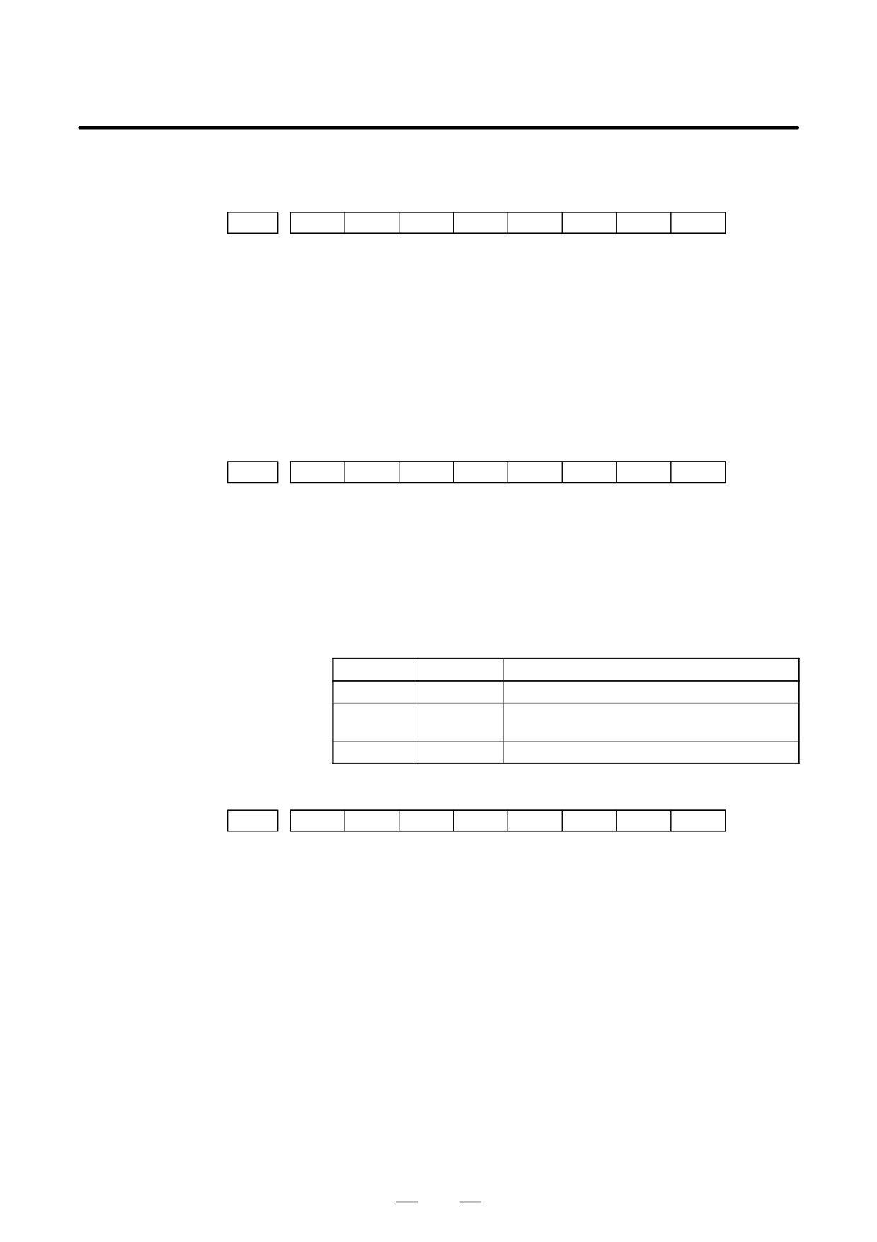
D Details of servo alarm
The details of servo alarm are displayed in the diagnosis display (No. 200
and No.204) as shown below.
#7
#6
#5
#4
#3
#2
#1
#0
200
OVL
LV
OVC
HCA
HVA
DCA
FBA
OFA
#7 (OVL) : An overload alarm is being generated.
#6 (LV) : A low voltage alarm is being generated in servo amp.
#5 (OVC) : A overcurrent alarm is being generated inside of digital servo.
#4 (HCA) : An abnormal current alarm is being generated in servo amp.
#3 (HVA) : An overvoltage alarm is being generated in servo amp.
#2 (DCA) : A regenerative discharge circuit alarm is being generated in servo amp.
#1 (FBA) : A disconnection alarm is being generated.
#0 (OFA) : An overflow alarm is being generated inside of digital servo.
#7
#6
#5
#4
#3
#2
#1
#0
201
ALD
EXP
When OVL equal 1 in diagnostic data No.200 (servo alarm No. 400 is
being generated):
#7 (ALD)
0 : Motor overheating
1 : Amplifier overheating
When FBAL equal 1 in diagnostic data No.200 (servo alarm No. 416 is
being generated):
ALD
EXP
Alarm details
1
0
Built-in pulse coder disconnection (hardware)
1
1
Separately installed pulse coder disconnection
(hardware)
0
0
Pulse coder is not connected due to software.
#7
#6
#5
#4
#3
#2
#1
#0
204
OFS
MCC
LDA
PMS
#6 (OFS) : A current conversion error has occured in the digital servo.
#5 (MCC) : A magnetic contactor contact in the servo amplifier has welded.
#4 (LDA) : The LED indicates that serial pulse coder C is defective.
#3 (PMS) : A feedback pulse error has occured because the feedback cable is
defective.
865
G. ALARM LIST
APPENDIX
B-63524EN/01
6) Over travel alamrs
Number
Message
Contents
500
OVER TRAVEL : +n
Exceeded the n-th axis (axis 1 to 8) + side stored stroke limit I.
(Parameter No.1320 or 1326 NOTE)
501
OVER TRAVEL : -n
Exceeded the n-th axis (axis 1 to 8) - side stored stroke limit I.
(Parameter No.1321 or 1327 NOTE)
502
OVER TRAVEL : +n
Exceeded the n-th axis (axis 1 to 8) + side stored stroke limit II.
(Parameter No.1322 )
503
OVER TRAVEL : -n
Exceeded the n-th axis (axis 1 to 8) - side stored stroke limit II.
(Parameter No.1323)
504
OVER TRAVEL : +n
Exceeded the n-th axis (axis 1 to 8) + side stored stroke limit III.
(Parameter No.1324 )
505
OVER TRAVEL : -n
Exceeded the n-th axis (axis 1 to 8) - side stored stroke limit III.
(Parameter No.1325 )
506
OVER TRAVEL : +n
Exceeded the n-th axis (axis 1 to 8) + side hardware OT.
507
OVER TRAVEL : -n
Exceeded the n-th axis (axis 1 to 8) - side hardware OT.
508
INTERFERENCE : +n
When n-axis is moving in the positive direction, it interferes with the
order tool post (only with two-path control)
509
INTERFERENCE : -n
When n-axis is moving in the negative direction, it interferes with the
order tool post (only with two-path control)
510
OVER TRAVEL : +n
A stroke limit check, made before starting movement, found that the
end point of a block falls within the plus (+) side inhibited area along
the n-axis defined by a stroke limit. Correct the program.
511
OVER TRAVEL : -n
A stroke limit check, made before starting movement, found that the
end point of a block falls within the minus (-) side inhibited area along
the N-axis defined by a stroke limit. Correct the program.
NOTE
Over travel alarms No. 504 and No. 505 are provided only with the T series.
Parameters 1326 and 1327 are effective when EXLM(stroke limit switch signal) is on.
7) Overheat alarms
Number
Message
Contents
700
OVERHEAT: CONTROL UNIT
Control unit overheat
Check that the fan motor operates normally, and clean the air filter.
701
OVERHEAT: FAN MOTOR
The fan motor on the top of the cabinet for the control unit is over-
heated. Check the operation of the fan motor and replace the motor if
necessary.
704
OVERHEAT: SPINDLE
Spindle overheat in the spindle fluctuation detection
(1)If the cutting load is heavy, relieve the cutting condition.
(2)Check whether the cutting tool is share.
(3)Another possible cause is a faulty spindle amp.
8) Rigid tapping alarm
Number
Message
Contents
740
RIGID TAP ALARM : EXCESS
During rigid tapping, the position deviation of the spindle in the stop
ERROR
state exceeded the setting.
741
RIGID TAP ALARM : EXCESS
During rigid tapping, the position deviation of the spindle in the stop
ERROR
state exceeded the setting.
742
RIGID TAP ALARM : LSI OVER
During rigid tapping, an LSI overflow occurred on the spindle side.
FLOW
866
B-63524EN/01
APPENDIX
G. ALARM LIST
9) Serial spindle alarms
Number
Message
Contents
749
S-SPINDLE LSI ERROR
It is serial communication error while system is executing after power
supply on. Following reasons can be considered.
1) Optical cable connection is fault or cable is not connected or cable
is cut.
2) MAIN CPU board or option 2 board is fault.
3) Spindle amp. printed board is fault.
If this alarm occurs when CNC power supply is turned on or when
this alarm can not be cleared even if CNC is reset, turn off the power
supply also turn off the power supply in spindle side.
750
SPINDLE SERIAL LINK START
This alarm is generated when the spindle control unit is not ready for
FAULT
starting correctly when the power is turned on in the system with the
serial spindle.
The four reasons can be considered as follows:
1) An improperly connected optic cable, or the spindle control unit’s
power is OFF.
2) When the NC power was turned on under alarm conditions other
than SU-01 or AL-24 which are shown on the LED display of the
spindle control unit.
In this case, turn the spindle amplifier power off once and perform
startup again.
3) Other reasons (improper combination of hardware)
This alarm does not occur after the system including the spindle con-
trol unit is activated.
4) The second spindle (when SP2, bit 4 of parameter No. 3701, is 1) is
in one of the above conditions 1) to 3).
See diagnostic display No. 409 for details.
752
FIRST SPINDLE MODE CHANGE
This alarm is generated if the system does not properly terminate a
FAULT
mode change. The modes include the Cs contouring, spindle position-
ing, rigid tapping, and spindle control modes. The alarm is activated if
the spindle control unit does not respond correctly to the mode change
command issued by the NC.
754
SPINDLE-1 ABNORMAL TORQUE
Abnormal first spindle motor load has been detected.
ALM
762
SECOND SPINDLE MODE
Refer to alarm No. 752. (For 2nd axis)
CHANGE FAULT
764
SPINDLE-2 ABNORMAL TORQUE
Same as alarm No. 754 (for the second spindle)
ALM
772
SPINDLE-3 MODE CHANGE
Same as alarm No. 752 (for the third spindle)
ERROR
774
SPINDLE-3 ABNORMAL TORQUE
Same as alarm No. 754 (for the third spindle)
ALM
782
SPINDLE-4 MODE CHANGE
Same as alarm number 752 (for the fourth spindle)
ERROR
784
SPINDLE-4 ABNORMAL TORQUE
Same as alarm number 754 (for the fourth spindle)
ALM
D The details of spindle
The details of spindle alarm No. 750 are displayed in the diagnosis display
alarm No.750
(No. 409) as shown below.
#7
#6
#5
#4
#3
#2
#1
#0
409
SPE
S2E
S1E
SHE
#3 (SPE)
0 : In the spindle serial control, the serial spindle parameters fulfill the
spindle unit startup conditions.
867
G. ALARM LIST
APPENDIX
B-63524EN/01
1 : In the spindle serial control, the serial spindle parameters do not fulfill
the spindle unit startup conditions.
#2 (S2E)
0 : The second spindle is normal during the spindle serial control startup.
1 : The second spindle was detected to have a fault during the spindle
serial control startup.
#1 (S1E)
0 : The first spindle is normal during the spindle serial control startup.
1 : The first spindle was detected to have a fault during the spindle axis
serial control startup.
#0 (SHE)
0 : The serial communications module in the CNC is normal.
1 : The serial communications module in the CNC was detected to have a
fault.
868
B-63524EN/01
APPENDIX
G. ALARM LIST
Alarm List (Serial Spindle)
When a serial spindle alarm occurs, the following number is displayed on
the CNC. n is a number corresponding to the spindle on which an alarm
occurs.
(n = 1: First spindle; n = 2: Second spindle; etc.)
NOTE*1
Note that the meanings of the SPM indications differ
depending on which LED, the red or yellow LED, is on.
When the red LED is on, the SPM indicates a 2-digit alarm
number. When the yellow LED is on, the SPM indicates an
error number that designates a sequence problem (for
example, when a rotation command is entered with the
emergency stop state not released).
³ See Appendix A.4, “Error Codes (Serial Spindle).”
Alarm Numbers and Alarms Displayed on the α Series Spindle Amplifier
SPM in-
No.
Message
dica-
Faulty location and remedy
Description
tion(*1)
(750)
SPINDLE SERIAL LINK
A0
1
Replace the ROM on the SPM
The program does not start normally.
ERROR
A
control printed circuit board.
ROM series error or hardware ab-
2
Replace the SPM control printed
normality on the SPM control printed
circuit board.
circuit board
(749)
S-SPINDLE LSI ERROR
A1
Replace the SPM control printed cir-
An abnormality was detected in the
cuit board.
CPU peripheral circuit of the SPM
control circuit.
7n01
SPN_n_ : MOTOR OVER-
01
1
Check and correct the peripheral
The thermostat embedded in the mo-
HEAT
temperature and load status.
tor winding operated.
2
If the cooling fan stops, replace it.
The internal temperature of the motor
exceeds the specified level.
The motor is used in excess of the
continuous rating, or the cooling com-
ponent is abnormal.
7n02
SPN_n_ : EX SPEED ER-
02
1
Check and correct the cutting
The motor speed cannot follow a spe-
ROR
conditions to decrease the load.
cified speed.
2
Correct parameter No. 4082.
An excessive motor load torque is de-
tected.
The acceleration/deceleration time in
parameter No. 4082 is insufficient.
7n03
SPN_n_ : FUSE ON DC
03
1
Replace the SPM unit.
The PSM becomes ready (00 is indi-
LINK BLOWN
2
Check the motor insulation status.
cated), but the DC link voltage is too
3
Replace the interface cable.
low in the SPM.
The fuse in the DC link section in the
SPM is blown. (The power device is
damaged or the motor is ground-
fault.)
The JX1A/JX1B connection cable is
abnormal.
7n06
SPN_n_ : THERMAL
06
1
Check and correct the parameter.
The temperature sensor of the motor
SENSOR DIS-
2
Replace the feedback cable.
is disconnected.
CONNECT
869
G. ALARM LIST
APPENDIX
B-63524EN/01
SPM in-
No.
Message
dica-
Faulty location and remedy
Description
tion(*1)
7n07
SPN_n_ : OVERSPEED
07
Check for a sequence error. (For ex-
The motor speed has exceeded
ample, check whether spindle syn-
115% of its rated speed.
chronization was specified when the
When the spindle axis was in position
spindle could not be turned.)
control mode, positional deviations
were accumulated excessively (SFR
and SRV were turned off during
spindle synchronization.)
7n09
SPN_n_ : OVERHEAT
09
1
Improve the heat sink cooling sta-
Abnormal temperature rise of the
MAIN CIRCUIT
tus.
power transistor radiator
2
If the heat sink cooling fan stops,
replace the SPM unit.
7n11
SPN_n_ : OVERVOLT
11
1
Check the selected PSM.
Overvoltage of the DC link section of
POW CIRCUIT
2
Check the input power voltage and
the PSM was detected. (PSM alarm
change in power during motor de-
indication: 7)
celeration. If the voltage exceeds
PSM selection error. (The maximum
253 VAC (for the 200-V system) or
output specification of the PSM is ex-
530 VAC (for the 400-V system),
ceeded.)
improve the power supply imped-
ance.
7n12
SPN_n_ : OVERCUR-
12
1
Check the motor insulation status.
The motor output current is abnormal-
RENT POW
2
Check the spindle parameters.
ly high.
CIRCUIT
3
Replace the SPM unit.
A motor-specific parameter does not
match the motor model.
Poor motor insulation
7n15
SPN_n_ : SP SWITCH
15
1
Check and correct the ladder se-
The switch sequence in spindle
CONTROL
quence.
switch/output switch operation is ab-
ALARM
2
Replace the switching MC.
normal.
The switching MC contact status
check signal and command do not
match.
7n16
SPN_n_ : RAM FAULT
16
Replace the SPM control printed cir-
Abnormality in an SPM control circuit
cuit board.
component is detected. (RAM for ex-
ternal data is abnormal.)
7n18
SPN_n_ : SUMCHECK
18
Replace the SPM control printed cir-
Abnormality in an SPM control circuit
ERROR PGM
cuit board.
component is detected.
(Program
DATA
ROM data is abnormal.)
7n19
SPN_n_ : EX OFFSET
19
Replace the SPM unit.
Abnormality in an SPM component is
CURRENT U
detected. (The initial value for the U
phase current detection circuit is ab-
normal.)
7n20
SPN_n_ : EX OFFSET
20
Replace the SPM unit.
Abnormality in an SPM component is
CURRENT V
detected.
(The initial value of the V
phase current detection circuit is ab-
normal.)
7n21
SPN_n_ : POS SENSOR
21
Check and correct the parameters.
The polarity parameter setting of the
POLARITY ER-
(No. 4000#0, 4001#4)
position sensor is wrong.
ROR
870
B-63524EN/01
APPENDIX
G. ALARM LIST
SPM in-
No.
Message
dica-
Faulty location and remedy
Description
tion(*1)
7n24
SPN_n_ : SERIAL
24
1
Place the CNC-to-spindle cable
The CNC power is turned off (normal
TRANSFER
away from the power cable.
power-off or broken cable).
ERROR
2
Replace the cable.
An error is detected in communica-
tion data transferred to the CNC.
7n26
SPN_n_ : DISCONNECT
26
1
Replace the cable.
The signal amplitude of the detection
C-VELO DE-
2
Re-adjust the pre-amplifier.
signal (connector JY2) on the Cs con-
TECT
tour control motor side is abnormal.
(Unconnected cable, adjustment er-
ror, etc.)
7n27
SPN_n_ : DISCONNECT
27
1
Replace the cable.
1
The spindle position coder (con-
POS-CODER
2
Re-adjust the BZ sensor signal.
nector JY4) signal is abnormal.
2
The signal amplitude (connector
JY2) of the MZ or BZ sensor is ab-
normal.
(Unconnected cable, adjustment
error, etc.)
7n28
SPN_n_ : DISCONNECT
28
1
Replace the cable
The position detection signal (con-
C-POS DE-
2
Re-adjust the pre-amplifier.
nector JY5) for Cs contour control is
TECT
abnormal.
(Unconnected cable, adjustment er-
ror, etc.)
7n29
SPN_n_ : SHORTTIME
29
Check and correct the load status.
Excessive load has been applied
OVERLOAD
continuously for a certain period of
time. (This alarm is issued also when
the motor shaft has been locked in the
excitation state.)
7n30
SPN_n_ : OVERCUR-
30
Check and correct the power supply
Overcurrent is detected in PSM main
RENT POW
voltage.
circuit input.
(PSM alarm indication:
CIRCUIT
1)
Unbalanced power supply.
PSM selection error (The maximum
PSM output specification is exceed-
ed.)
7n31
SPN_n_ : MOTOR LOCK
31
1
Check and correct the load status.
The motor cannot rotate at a specified
OR V-SIG LOS
2
Replace the motor sensor cable
speed.
(A level not exceeding the
(JY2 or JY5).
SST level for the rotation command
has existed continuously.)
Abnormality in the speed detection
signal.
7n32
SPN_n_ : RAM FAULT
32
Replace the SPM control printed cir-
Abnormality in an SPM control circuit
SERIAL LSI
cuit board.
component is detected. (The LSI de-
vice for serial transfer is abnormal.)
7n33
SPN_n_ : SHORTAGE
33
1
Check and correct the power sup-
Charging of direct current power sup-
POWER
ply voltage.
ply voltage in the power circuit section
CHARGE
2
Replace the PSM unit.
is insufficient when the magnetic con-
tractor in the amplifier is turned on
(such as open phase and defective
charging resistor).
871
G. ALARM LIST
APPENDIX
B-63524EN/01
SPM in-
No.
Message
dica-
Faulty location and remedy
Description
tion(*1)
7n34
SPN_n_ : PARAMETER
34
Correct a parameter value according
Parameter data exceeding the allow-
SETTING ER-
to the manual.
able limit is set.
ROR
If the parameter number is unknown,
connect the spindle check board, and
check the indicated parameter.
7n35
SPN_n_ : EX SETTING
35
Correct the value according to the pa-
Gear ratio data exceeding the allow-
GEAR RATIO
rameter manual.
able limit is set.
7n36
SPN_n_ : OVERFLOW
36
Check whether the position gain val-
An error counter overflow occurred.
ERROR
ue is too large, and correct the value.
COUNTER
7n37
SPN_n_ : SPEED DE-
37
Correct the value according to the pa-
The setting of the parameter for the
TECT PAR. ER-
rameter manual.
number of pulses in the speed detec-
ROR
tor is incorrect.
7n39
SPN_n_ :
1-ROT Cs SIG-
39
1
Adjust the 1-rotation signal in the
An incorrect relationship between the
NAL ERROR
pre-amplifier.
1-rotation signal and the number of
2
Check the cable shield status.
AB phase pulses was detected dur-
3
Replace the cable.
ing Cs contour control.
7n40
SPN_n_ : NO 1-ROT Cs
40
1
Adjust the 1-rotation signal in the
The 1-rotation signal is not gener-
SIGNAL DE-
pre-amplifier.
ated during Cs contour control.
TECT
2
Check the cable shield status.
3
Replace the cable.
7n41
SPN_n_ :
1-ROT POS-
41
1
Check and correct the parameter.
1
The
1-rotation signal of the
CODER ER-
2
Replace the cable.
spindle position coder (connector
ROR
3
Re-adjust the BZ sensor signal.
JY4) is abnormal.
2
The 1-rotation signal (connector
JY2) of the MZ or BZ sensor is ab-
normal.
3
Parameter setting error
7n42
SPN_n_ : NO 1-ROT.
42
1
Replace the cable.
1
The
1-rotation signal of the
POS-CODER
2
Re-adjust the BZ sensor signal.
spindle position coder (connector
DETECT
JY4) is disconnected.
2
The 1-rotation signal (connector
JY2) of the MZ or BZ sensor is dis-
connected.
7n43
SPN_n_ : DISCON. PC
43
Replace the cable.
The differential speed position coder
FOR DIF. SP.
signal (connector JY8) in SPM type 3
MODE
is abnormal.
7n44
SPN_n_ : CONTROL
44
Replace the SPM control printed cir-
Abnormality in an SPM control circuit
CIRCUIT(AD)
cuit board.
component was detected (A/D con-
ERROR
verter abnormality).
7n46
SPN_n_ : SCREW
46
1
Check and correct the parameter.
An abnormality equivalent to alarm
1-ROT POS-
2
Replace the cable.
41 was detected during thread cutting
COD. ALARM
3
Re-adjust the BZ sensor signal.
operation.
872
B-63524EN/01
APPENDIX
G. ALARM LIST
SPM in-
No.
Message
dica-
Faulty location and remedy
Description
tion(*1)
7n47
SPN_n_ : POS-CODER
47
1
Replace the cable.
1
The A/B phase signal of the
SIGNAL AB-
2
Re-adjust the BZ sensor signal.
spindle position coder (connector
NORMAL
3
Correct the cable layout (vicinity of
JY4) is abnormal.
the power line).
2
The A/B phase signal (connector
JY2) of the MZ or BZ sensor is ab-
normal.
The relationship between the A/B
phase and 1-rotation signal is incor-
rect (Pulse interval mismatch).
7n49
SPN_n_ : HIGH CONV.
49
Check whether the calculated differ-
In differential speed mode, the speed
DIF. SPEED
ential speed value exceeds the maxi-
of the other spindle converted to the
mum motor speed.
speed of the local spindle has ex-
ceeded the allowable limit (the differ-
ential speed is calculated by multiply-
ing the speed of the other spindle by
the gear ratio).
7n50
SPN_n_ : SPNDL CON-
50
Check whether the calculated value
In spindle synchronization, the speed
TROL OVER-
exceeds the maximum motor speed.
command calculation value exceed-
SPEED
ed the allowable limit
(the motor
speed is calculated by multiplying the
specified spindle speed by the gear
ratio).
7n51
SPN_n_ : LOW VOLT DC
51
1
Check and correct the power sup-
Input voltage drop was detected.
LINK
ply voltage.
(PSM alarm indication: 4) (Momen-
2
Replace the MC.
tary power failure or poor MC contact)
7n52
SPN_n_ : ITP SIGNAL
52
1
Replace the SPM control printed
NC interface abnormality was de-
ABNORMAL I
circuit board.
tected (the ITP signal stopped).
2
Replace the spindle interface
printed circuit board in the CNC.
7n53
SPN_n_ : ITP SIGNAL
53
1
Replace the SPM control printed
NC interface abnormality was de-
ABNORMAL II
circuit board.
tected (the ITP signal stopped).
2
Replace the spindle interface
printed circuit board in the CNC.
7n54
SPN_n_ : OVERLOAD
54
Review the load state.
An overload current was detected.
CURRENT
7n55
SPN_n_ : POWER LINE
55
1
Replace the magnetic contactor.
The power line state signal of the
SWITCH ER-
2
Check and correct the sequence.
magnetic contactor for selecting a
ROR
spindle or output is abnormal.
7n56
SPN_n_ : INNER COOL-
56
Replace the SPM unit.
The cooling fan in the SPM control cir-
ING FAN STOP
cuit stopped.
7n57
SPN_n_ : EX DECEL-
57
1
Decrease the acceleration/decel-
An overload was detected in the re-
ERATION
eration duty.
generative resistance. (PSMR alarm
POWER
2
Check the cooling condition (pe-
indication: 8)
ripheral temperature).
Thermostat operation or short-time
3
If the cooling fan stops, replace the
overload was detected.
resistor.
The regenerative resistor was dis-
4
If the resistance is abnormal, re-
connected, or an abnormal resis-
place the resistor.
tance was detected.
873
G. ALARM LIST
APPENDIX
B-63524EN/01
SPM in-
No.
Message
dica-
Faulty location and remedy
Description
tion(*1)
7n58
SPN_n_ : OVERLOAD IN
58
1
Check the PSM cooling status.
The temperature of the radiator of the
PSM
2
Replace the PSM unit.
PSM has increased abnormally.
(PSM alarm indication: 3)
7n59
SPN_n_ : COOLING FAN
59
Replace the SPM unit.
The cooling fan in the PSM stopped.
STOP IN PSM
(PSM alarm indication: 2)
7n62
SPN_n_ : MOTOR VCMD
62
Check and correct the parameters.
The specified motor speed is too
OVERFLOWED
(No. 4021, 4056 to 4059)
large.
7n66
SPN_n_ : AMP MODULE
66
1
Replace the cable.
An error was found in communication
COMMUNICA-
2
Check and correct the connection.
between amplifiers.
TION
7n73
SPN_n_ : MOTOR SEN-
73
1
Replace the feedback cable.
The motor sensor feedback signal is
SOR DISCON-
2
Check the shield processing.
not present.
NECTED
3
Check and correct the connection.
4
Adjust the sensor.
7n74
SPN_n_ : CPU TEST ER-
74
Replace the SPM control printed-cir-
An error was detected in a CPU test.
ROR
cuit board.
7n75
SPN_n_ : CRC ERROR
75
Replace the SPM control printed-cir-
An error was detected in a CRC test.
cuit board.
7n79
SPN_n_ : INITIAL TEST
79
Replace the SPM control printed-cir-
An error was detected in an initial test
ERROR
cuit board.
operation.
7n81
SPN_n_ :
1-ROT MO-
81
1
Check and correct the parameter.
The one-rotation signal of the motor
TOR SENSOR
2
Replace the feedback cable.
sensor cannot be correctly detected.
ERROR
3
Adjust the sensor.
7n82
SPN_n_ : NO 1-ROT
82
1
Replace the feedback cable.
The one-rotation signal of the motor
MOTOR SEN-
2
Adjust the sensor.
sensor is not generated.
SOR
7n83
SPN_n_ : MOTOR SEN-
83
1
Replace the feedback cable.
An irregularity was detected in a mo-
SOR SIGNAL
2
Adjust the sensor.
tor sensor feedback signal.
ERROR
7n84
SPN_n_ : SPNDL SEN-
84
1
Replace the feedback cable.
The spindle sensor feedback signal is
SOR DISCON-
2
Check the shield processing.
not present.
NECTED
3
Check and correct the connection.
4
Check and correct the parameter.
5
Adjust the sensor.
7n85
SPN_n_ :
1-ROT SPNDL
85
1
Check and correct the parameter.
The one-rotation signal of the spindle
SENSOR ER-
2
Replace the feedback cable.
sensor cannot be correctly detected.
ROR
3
Adjust the sensor.
7n87
SPN_n_ : SPNDL SEN-
87
The one-rotation signal of the spindle
An irregularity was detected in a
SOR SIGNAL
sensor is not generated.
spindle sensor feedback signal.
ERROR
7n88
SPN_n_ : COOLING RA-
88
Replace the SPM external cooling
The external cooling fan stopped.
DIFAN FAIL-
fan.
URE
874
B-63524EN/01
APPENDIX
G. ALARM LIST
SPM in-
No.
Message
dica-
Faulty location and remedy
Description
tion(*1)
7n97
SPN_n_ : OTHER
97
Replace the SPM.
Another irregularity was detected.
SPINDLE
ALARM
7n98
SPN_n_ : OTHER CON-
98
Check the PSM alarm display.
A PSM alarm was detected.
VERTER
ALARM
SPM in-
No.
Message
dica-
Faulty location and remedy
Description
tion(*1)
9n01
SPN_n_ : MOTOR OVER-
01
1
Check and correct the peripheral
The thermostat embedded in the mo-
HEAT
temperature and load status.
tor winding operated.
2
If the cooling fan stops, replace it.
The internal temperature of the motor
exceeds the specified level.
The motor is used in excess of the
continuous rating, or the cooling com-
ponent is abnormal.
9n02
SPN_n_ : EX SPEED ER-
02
1
Check and correct the cutting
The motor speed cannot follow a spe-
ROR
conditions to decrease the load.
cified speed.
2
Correct parameter No. 4082.
An excessive motor load torque is de-
tected.
The acceleration/deceleration time in
parameter No. 4082 is insufficient.
9n03
SPN_n_ : FUSE ON DC
03
1
Replace the SPM unit.
The PSM becomes ready (00 is indi-
LINK BLOWN
2
Check the motor insulation status.
cated), but the DC link voltage is too
3
Replace the interface cable.
low in the SPM.
The fuse in the DC link section in the
SPM is blown. (The power device is
damaged or the motor is ground-
fault.)
The JX1A/JX1B connection cable is
abnormal.
9n06
06
1
Check and correct the parameter.
The temperature sensor of the motor
2
Replace the feedback cable.
is disconnected.
9n07
SPN_n_ : OVERSPEED
07
Check for a sequence error. (For ex-
The motor speed has exceeded
ample, check whether spindle syn-
115% of its rated speed.
chronization was specified when the
When the spindle axis was in position
spindle could not be turned.)
control mode, positional deviations
were accumulated excessively (SFR
and SRV were turned off during
spindle synchronization.)
9n09
SPN_n_ : OVERHEAT
09
1
Improve the heat sink cooling sta-
Abnormal temperature rise of the
MAIN CIRCUIT
tus.
power transistor radiator
2
If the heat sink cooling fan stops,
replace the SPM unit.
875
G. ALARM LIST
APPENDIX
B-63524EN/01
SPM in-
No.
Message
dica-
Faulty location and remedy
Description
tion(*1)
9n11
SPN_n_ : OVERVOLT
11
1
Check the selected PSM.
Overvoltage of the DC link section of
POW CIRCUIT
2
Check the input power voltage and
the PSM was detected. (PSM alarm
change in power during motor de-
indication: 7)
celeration. If the voltage exceeds
PSM selection error. (The maximum
253 VAC (for the 200-V system) or
output specification of the PSM is ex-
530 VAC (for the 400-V system),
ceeded.)
improve the power supply imped-
ance.
9n12
SPN_n_ : OVERCUR-
12
1
Check the motor insulation status.
The motor output current is abnormal-
RENT POW
2
Check the spindle parameters.
ly high.
CIRCUIT
3
Replace the SPM unit.
A motor-specific parameter does not
match the motor model.
Poor motor insulation
9n15
SPN_n_ : SP SWITCH
15
1
Check and correct the ladder se-
The switch sequence in spindle
CONTROL
quence.
switch/output switch operation is ab-
ALARM
2
Replace the switching MC.
normal.
The switching MC contact status
check signal and command do not
match.
9n16
SPN_n_ : RAM FAULT
16
Replace the SPM control printed cir-
Abnormality in an SPM control circuit
cuit board.
component is detected. (RAM for ex-
ternal data is abnormal.)
9n18
SPN_n_ : SUMCHECK
18
Replace the SPM control printed cir-
Abnormality in an SPM control circuit
ERROR PGM
cuit board.
component is detected.
(Program
DATA
ROM data is abnormal.)
9n19
SPN_n_ : EX OFFSET
19
Replace the SPM unit.
Abnormality in an SPM component is
CURRENT U
detected. (The initial value for the U
phase current detection circuit is ab-
normal.)
9n20
SPN_n_ : EX OFFSET
20
Replace the SPM unit.
Abnormality in an SPM component is
CURRENT V
detected.
(The initial value of the V
phase current detection circuit is ab-
normal.)
9n21
SPN_n_ : POS SENSOR
21
Check and correct the parameters.
The polarity parameter setting of the
POLARITY ER-
(No. 4000#0, 4001#4)
position sensor is wrong.
ROR
9n24
SPN_n_ : SERIAL
24
1
Place the CNC-to-spindle cable
The CNC power is turned off (normal
TRANSFER
away from the power cable.
power-off or broken cable).
ERROR
2
Replace the cable.
An error is detected in communica-
tion data transferred to the CNC.
9n26
SPN_n_ : DISCONNECT
26
1
Replace the cable.
The signal amplitude of the detection
C-VELO DE-
2
Re-adjust the pre-amplifier.
signal (connector JY2) on the Cs con-
TECT
tour control motor side is abnormal.
(Unconnected cable, adjustment er-
ror, etc.)
876
B-63524EN/01
APPENDIX
G. ALARM LIST
SPM in-
No.
Message
dica-
Faulty location and remedy
Description
tion(*1)
9n27
SPN_n_ : DISCONNECT
27
1
Replace the cable.
1
The spindle position coder (con-
POS-CODER
2
Re-adjust the BZ sensor signal.
nector JY4) signal is abnormal.
2
The signal amplitude (connector
JY2) of the MZ or BZ sensor is ab-
normal.
(Unconnected cable, adjustment
error, etc.)
9n28
SPN_n_ : DISCONNECT
28
1
Replace the cable
The position detection signal (con-
C-POS DE-
2
Re-adjust the pre-amplifier.
nector JY5) for Cs contour control is
TECT
abnormal.
(Unconnected cable, adjustment er-
ror, etc.)
9n29
SPN_n_ : SHORTTIME
29
Check and correct the load status.
Excessive load has been applied
OVERLOAD
continuously for a certain period of
time. (This alarm is issued also when
the motor shaft has been locked in the
excitation state.)
9n30
SPN_n_ : OVERCUR-
30
Check and correct the power supply
Overcurrent is detected in PSM main
RENT POW
voltage.
circuit input.
(PSM alarm indication:
CIRCUIT
1)
Unbalanced power supply.
PSM selection error (The maximum
PSM output specification is exceed-
ed.)
9n31
SPN_n_ : MOTOR LOCK
31
1
Check and correct the load status.
The motor cannot rotate at a specified
OR V-SIG LOS
2
Replace the motor sensor cable
speed.
(A level not exceeding the
(JY2 or JY5).
SST level for the rotation command
has existed continuously.)
Abnormality in the speed detection
signal.
9n32
SPN_n_ : RAM FAULT
32
Replace the SPM control printed cir-
Abnormality in an SPM control circuit
SERIAL LSI
cuit board.
component is detected. (The LSI de-
vice for serial transfer is abnormal.)
9n33
SPN_n_ : SHORTAGE
33
1
Check and correct the power sup-
Charging of direct current power sup-
POWER
ply voltage.
ply voltage in the power circuit section
CHARGE
2
Replace the PSM unit.
is insufficient when the magnetic con-
tractor in the amplifier is turned on
(such as open phase and defective
charging resistor).
9n34
SPN_n_ : PARAMETER
34
Correct a parameter value according
Parameter data exceeding the allow-
SETTING ER-
to the manual.
able limit is set.
ROR
If the parameter number is unknown,
connect the spindle check board, and
check the indicated parameter.
9n35
SPN_n_ : EX SETTING
35
Correct the value according to the pa-
Gear ratio data exceeding the allow-
GEAR RATIO
rameter manual.
able limit is set.
9n36
SPN_n_ : OVERFLOW
36
Check whether the position gain val-
An error counter overflow occurred.
ERROR
ue is too large, and correct the value.
COUNTER
877
G. ALARM LIST
APPENDIX
B-63524EN/01
SPM in-
No.
Message
dica-
Faulty location and remedy
Description
tion(*1)
9n37
SPN_n_ : SPEED DE-
37
Correct the value according to the pa-
The setting of the parameter for the
TECT PAR. ER-
rameter manual.
number of pulses in the speed detec-
ROR
tor is incorrect.
9n39
SPN_n_ :
1-ROT Cs SIG-
39
1
Adjust the 1-rotation signal in the
An incorrect relationship between the
NAL ERROR
pre-amplifier.
1-rotation signal and the number of
2
Check the cable shield status.
AB phase pulses was detected dur-
3
Replace the cable.
ing Cs contour control.
9n40
SPN_n_ : NO 1-ROT Cs
40
1
Adjust the 1-rotation signal in the
The 1-rotation signal is not gener-
SIGNAL DE-
pre-amplifier.
ated during Cs contour control.
TECT
2
Check the cable shield status.
3
Replace the cable.
9n41
SPN_n_ :
1-ROT POS-
41
1
Check and correct the parameter.
1
The
1-rotation signal of the
CODER ER-
2
Replace the cable.
spindle position coder (connector
ROR
3
Re-adjust the BZ sensor signal.
JY4) is abnormal.
2
The 1-rotation signal (connector
JY2) of the MZ or BZ sensor is ab-
normal.
3
Parameter setting error
9n42
SPN_n_ : NO 1-ROT.
42
1
Replace the cable.
1
The
1-rotation signal of the
POS-CODER
2
Re-adjust the BZ sensor signal.
spindle position coder (connector
DETECT
JY4) is disconnected.
2
The 1-rotation signal (connector
JY2) of the MZ or BZ sensor is dis-
connected.
9n43
SPN_n_ : DISCON. PC
43
Replace the cable.
The differential speed position coder
FOR DIF. SP.
signal (connector JY8) in SPM type 3
MODE
is abnormal.
9n44
SPN_n_ : CONTROL
44
Replace the SPM control printed cir-
Abnormality in an SPM control circuit
CIRCUIT(AD)
cuit board.
component was detected (A/D con-
ERROR
verter abnormality).
9n46
SPN_n_ : SCREW
46
1
Check and correct the parameter.
An abnormality equivalent to alarm
1-ROT POS-
2
Replace the cable.
41 was detected during thread cutting
COD. ALARM
3
Re-adjust the BZ sensor signal.
operation.
9n47
SPN_n_ : POS-CODER
47
1
Replace the cable.
1
The A/B phase signal of the
SIGNAL AB-
2
Re-adjust the BZ sensor signal.
spindle position coder (connector
NORMAL
3
Correct the cable layout (vicinity of
JY4) is abnormal.
the power line).
2
The A/B phase signal (connector
JY2) of the MZ or BZ sensor is ab-
normal.
The relationship between the A/B
phase and 1-rotation signal is incor-
rect (Pulse interval mismatch).
9n49
SPN_n_ : HIGH CONV.
49
Check whether the calculated differ-
In differential speed mode, the speed
DIF. SPEED
ential speed value exceeds the maxi-
of the other spindle converted to the
mum motor speed.
speed of the local spindle has ex-
ceeded the allowable limit (the differ-
ential speed is calculated by multiply-
ing the speed of the other spindle by
the gear ratio).
878
B-63524EN/01
APPENDIX
G. ALARM LIST
SPM in-
No.
Message
dica-
Faulty location and remedy
Description
tion(*1)
9n50
SPN_n_ : SPNDL CON-
50
Check whether the calculated value
In spindle synchronization, the speed
TROL OVER-
exceeds the maximum motor speed.
command calculation value exceed-
SPEED
ed the allowable limit
(the motor
speed is calculated by multiplying the
specified spindle speed by the gear
ratio).
9n51
SPN_n_ : LOW VOLT DC
51
1
Check and correct the power sup-
Input voltage drop was detected.
LINK
ply voltage.
(PSM alarm indication: 4) (Momen-
2
Replace the MC.
tary power failure or poor MC contact)
9n52
SPN_n_ : ITP SIGNAL
52
1
Replace the SPM control printed
NC interface abnormality was de-
ABNORMAL I
circuit board.
tected (the ITP signal stopped).
2
Replace the spindle interface
printed circuit board in the CNC.
9n53
SPN_n_ : ITP SIGNAL
53
1
Replace the SPM control printed
NC interface abnormality was de-
ABNORMAL II
circuit board.
tected (the ITP signal stopped).
2
Replace the spindle interface
printed circuit board in the CNC.
9n54
SPN_n_ : OVERLOAD
54
Review the load state.
An overload current was detected.
CURRENT
9n55
SPN_n_ : POWER LINE
55
1
Replace the magnetic contactor.
The power line state signal of the
SWITCH ER-
2
Check and correct the sequence.
magnetic contactor for selecting a
ROR
spindle or output is abnormal.
9n56
SPN_n_ : INNER COOL-
56
Replace the SPM unit.
The cooling fan in the SPM control cir-
ING FAN STOP
cuit stopped.
9n57
SPN_n_ : EX DECEL-
57
1
Decrease the acceleration/decel-
An overload was detected in the re-
ERATION
eration duty.
generative resistance. (PSMR alarm
POWER
2
Check the cooling condition (pe-
indication: 8)
ripheral temperature).
Thermostat operation or short-time
3
If the cooling fan stops, replace the
overload was detected.
resistor.
The regenerative resistor was dis-
4
If the resistance is abnormal, re-
connected, or an abnormal resis-
place the resistor.
tance was detected.
9n58
SPN_n_ : OVERLOAD IN
58
1
Check the PSM cooling status.
The temperature of the radiator of the
PSM
2
Replace the PSM unit.
PSM has increased abnormally.
(PSM alarm indication: 3)
9n59
SPN_n_ : COOLING FAN
59
Replace the SPM unit.
The cooling fan in the PSM stopped.
STOP IN PSM
(PSM alarm indication: 2)
9n62
SPN_n_ : MOTOR VCMD
62
Check and correct the parameters.
The specified motor speed is too
OVERFLOWED
(No. 4021, 4056~4059)
large.
9n66
SPN_n_ : AMP MODULE
66
1
Replace the cable.
An error was found in communication
COMMUNICA-
2
Check and correct the connection.
between amplifiers.
TION
9n73
SPN_n_ : MOTOR SEN-
73
1
Replace the feedback cable.
The motor sensor feedback signal is
SOR DISCON-
2
Check the shield processing.
not present.
NECTED
3
Check and correct the connection.
4
Adjust the sensor.
879
G. ALARM LIST
APPENDIX
B-63524EN/01
SPM in-
No.
Message
dica-
Faulty location and remedy
Description
tion(*1)
9n74
SPN_n_ : CPU TEST ER-
74
Replace the SPM control printed-cir-
An error was detected in a CPU test.
ROR
cuit board.
9n75
SPN_n_ : CRC ERROR
75
Replace the SPM control printed-cir-
An error was detected in a CRC test.
cuit board.
9n79
SPN_n_ : INITIAL TEST
79
Replace the SPM control printed-cir-
An error was detected in an initial test
ERROR
cuit board.
operation.
9n81
SPN_n_ :
1-ROT MO-
81
1
Check and correct the parameter.
The one-rotation signal of the motor
TOR SENSOR
2
Replace the feedback cable.
sensor cannot be correctly detected.
ERROR
3
Adjust the sensor.
9n82
SPN_n_ : NO 1-ROT
82
1
Replace the feedback cable.
The one-rotation signal of the motor
MOTOR SEN-
2
Adjust the sensor.
sensor is not generated.
SOR
9n83
SPN_n_ : MOTOR SEN-
83
1
Replace the feedback cable.
An irregularity was detected in a mo-
SOR SIGNAL
2
Adjust the sensor.
tor sensor feedback signal.
ERROR
9n84
SPN_n_ : SPNDL SEN-
84
1
Replace the feedback cable.
The spindle sensor feedback signal is
SOR DISCON-
2
Check the shield processing.
not present.
NECTED
3
Check and correct the connection.
4
Check and correct the parameter.
5
Adjust the sensor.
9n85
SPN_n_ :
1-ROT SPNDL
85
1
Check and correct the parameter.
The one-rotation signal of the spindle
SENSOR ER-
2
Replace the feedback cable.
sensor cannot be correctly detected.
ROR
3
Adjust the sensor.
9n87
SPN_n_ : SPNDL SEN-
87
The one-rotation signal of the spindle
An irregularity was detected in a
SOR SIGNAL
sensor is not generated.
spindle sensor feedback signal.
ERROR
9n88
SPN_n_ : COOLING RA-
88
Replace the SPM external cooling
The external cooling fan stopped.
DIFAN FAIL-
fan.
URE
880
B-63524EN/01
APPENDIX
G. ALARM LIST
10) System alarms
(These alarms cannot be reset with reset key.)
Number
Message
Contents
900
ROM PARITY
A parity error occurred in the CNC, macro, or servo ROM. Correct the
contents of the flash ROM having the displayed number.
910
SRAM PARITY : (BYTE 0)
A RAM parity error occurred in the part program storage RAM. Clear
the RAM, or replace the SRAM module or motherboard. Subsequent-
911
SRAM PARITY : (BYTE 1)
ly, re-set the parameters and all other data.
912
DRAM PARITY : (BYTE 0)
A RAM parity error occurred in the DRAM module. Replace the
DRAM module.
913
DRAM PARITY : (BYTE 1)
914
DRAM PARITY : (BYTE 2)
915
DRAM PARITY : (BYTE 3)
916
DRAM PARITY : (BYTE 4)
917
DRAM PARITY : (BYTE 5)
918
DRAM PARITY : (BYTE 6)
919
DRAM PARITY : (BYTE 7)
920
SERVO ALARM (1-4 AXIS)
Servo alarm (first to fourth axis). A watchdog alarm condition oc-
curred, or a RAM parity error occurred in the axis control card.
Replace the axis control card.
921
SERVO ALARM (5-8 AXIS)
Servo alarm (fifth to eighth axis). A watchdog alarm condition oc-
curred, or a RAM parity error occurred in the axis control card.
Replace the axis control card.
926
FSSB ALARM
FSSB alarm.
Replace the axis control card.
930
CPU INTERRUPT
CPU error (abnormal interrupt).
The motherboard or CPU card may be faulty.
935
SRAM ECC ERROR
An error occurred in RAM for part program storage.
Action:
Replace the master printed circuit board (SRAM module), perform
all-clear operation, and set all parameter and other data again.
950
PMC SYSTEM ALARM
An error occurred in the PMC.
The PMC control circuit on the motherboard may be faulty.
951
PMC WATCH DOG ALARM
An error occurred in the PMC.
(Watchdog alarm)
The motherboard may be faulty.
972
NMI OCCURRED IN OTHER MOD-
An NMI occurred on a board other than the motherboard.
ULE
The option board may be faulty.
973
NON MASK INTERRUPT
An NMI occurred as a result of an unknown cause.
974
F-BUS ERROR
A bus error occurred on the FANUC bus.
The motherboard or option board may be faulty.
975
BUS ERROR
A bus error occurred on the motherboard.
The motherboard may be faulty.
976
L-BUS ERROR
A bus error occurred on the local bus.
The motherboard may be faulty.
881