FANUC Series Series 16i-TB, Series 18i-TB, Series 160i-TB, Series 180i-TB. OPERATOR’S MANUAL - page 19
B-63524EN/01
OPERATION
4. AUTOMATIC OPERATION
D Macro call
When the custom macro option is provided, macro programs can also be
created, called, and executed in the MDI mode. However, macro call
commands cannot be executed when the mode is changed to MDI mode
after memory operation is stopped during execution of a subprogram.
D Memory area
When a program is created in the MDI mode, an empty area in program
memory is used. If program memory is full, no programs can be created
in the MDI mode.
519
4. AUTOMATIC OPERATION
OPERATION
B-63524EN/01
This function specifies Sequence No. or Block No. of a block to be
4.3
restarted when a tool is broken down or when it is desired to restart
PROGRAM RESTART
machining operation after a day off, and restarts the machining operation
from that block. It can also be used as a high-speed program check
function.
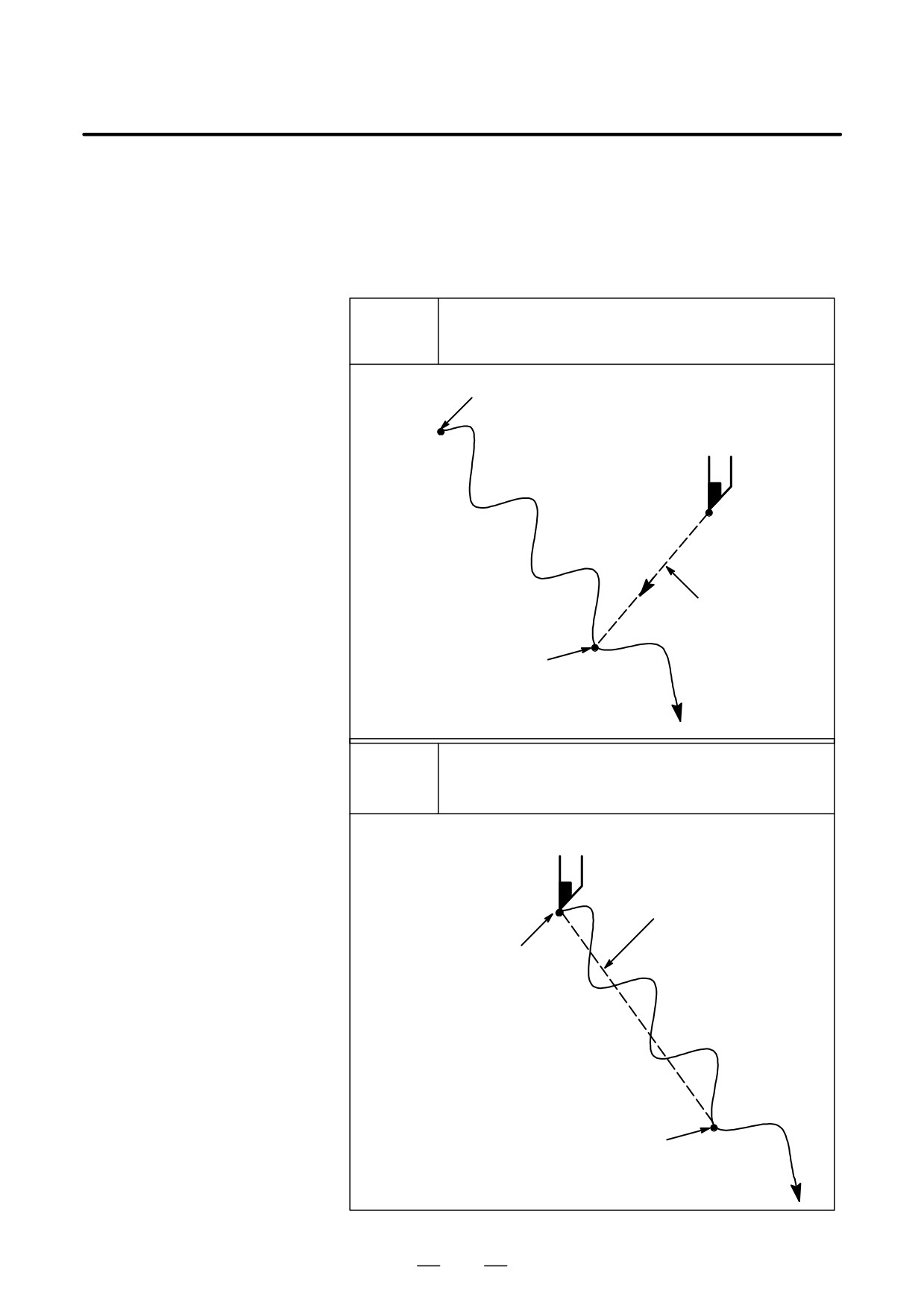
There are two restart methods: the P-type method and Q-type method.
Operation can be restarted anywhere. This restart method
P TYPE
is used when operation is stopped because of a broken tool.
Program start point (machining start point)
Return operation
Restart position
Before operation can be restarted, the machine must be
Q TYPE
moved to the programmed start point (machining start point)
Return operation
Program start point
(machining start point)
Restart position
520
B-63524EN/01
OPERATION
4. AUTOMATIC OPERATION
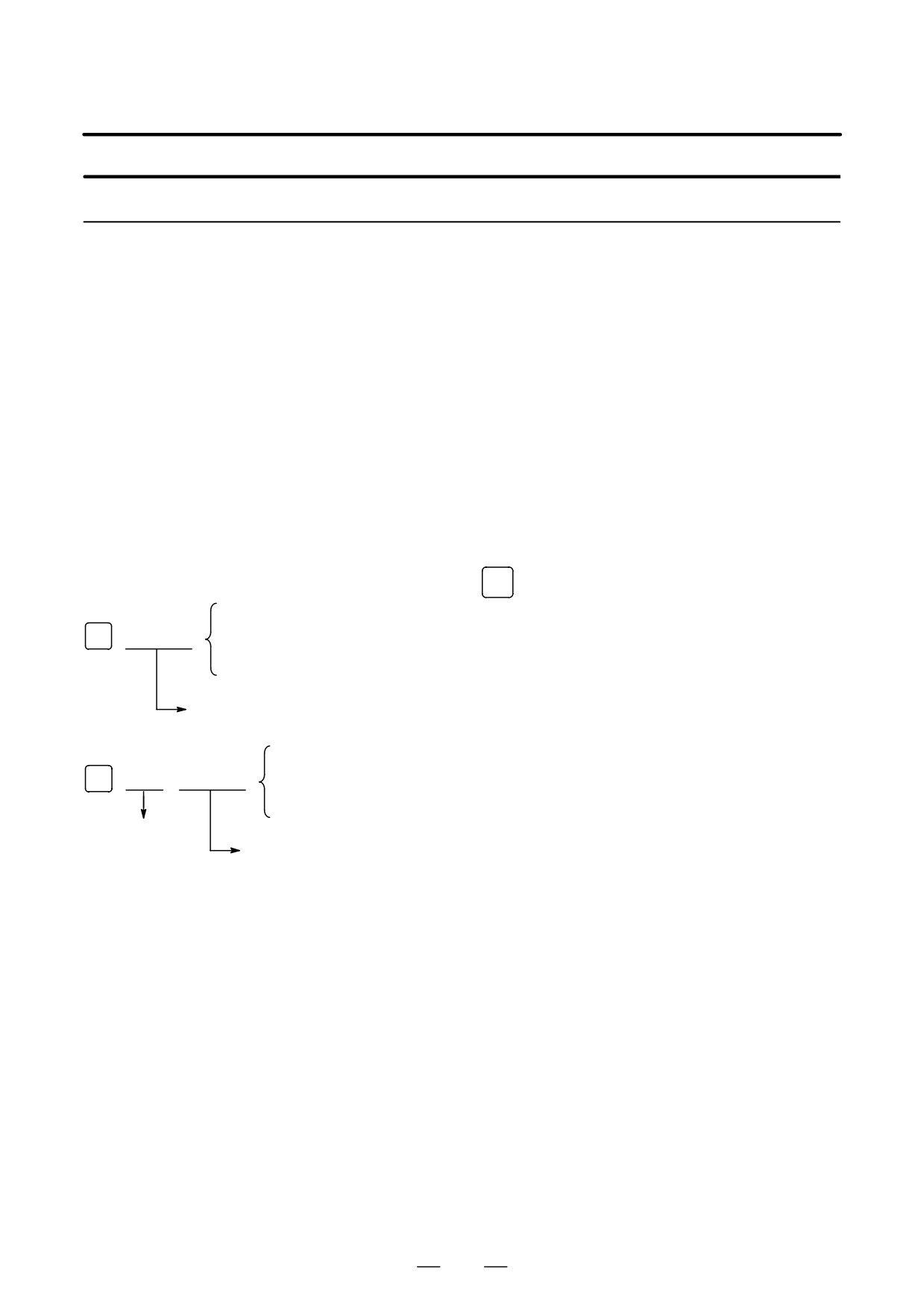
Procedure for Program restart by Specifying a sequence number
Procedure 1
[ P TYPE ]
1
Retract the tool and replace it with a new one. When necessary,
change the offset.
(Go to step 2.)
[ Q TYPE ]
1
When power is turned ON or emergency stop is released, perform all
necessary operations at that time, including the reference position
return.
2
Move the machine manually to the program starting point (machining
start point), and keep the modal data and coordinate system in the
same conditions as at the machining start.
3
If necessary, modify the offset amount.
Procedure 2
[COMMON TO P TYPE /
1
Turn the program restart switch on the machine operator’s panel ON.
Q TYPE]
2
Press function
PROG
key to display the desired program.
[Q TYPE]
3
Find the program head.
N
fffff or
4
Enter the sequence number of the block to be restarted, then press the
[P TYPE]
[P TYPE] or [Q TYPE] soft key.
Sequence number
[Q TYPE]
N
fff
fffff
or
If the same sequence number appears more than once, the location of
[P TYPE]
the target block must be specified. Specify a frequency and a
Frequency
sequence number.
Sequence number
521
4. AUTOMATIC OPERATION
OPERATION
B-63524EN/01
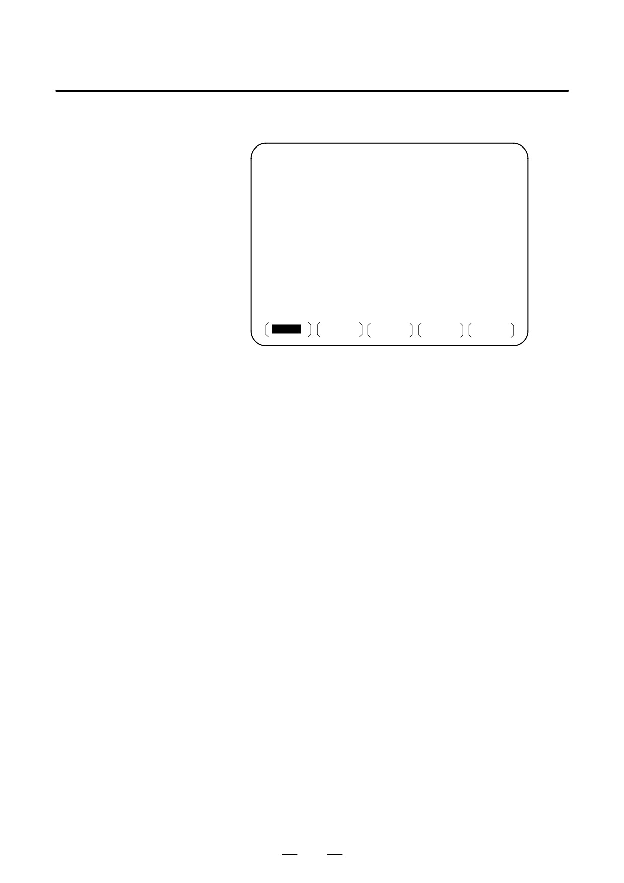
5
The sequence number is searched for, and the program restart screen
appears on the CRT display.
PROGRAM RESTART
O0002 N00100
DESTINATION
M
1
2
X 57. 096
1
2
Z 56. 943
1
2
1
2
1
2
1
* * * * * * * *
DISTANCE TO GO
* * * * * * * *
* * * * * * * *
1 X 1. 459
T * * * * * * * *
* * * * * * * *
2 Z 7. 320
S * * * * *
S
0 T0000
MEM * * * *
* * *
* * *
10 : 10 : 40
RSTR
FL.SDL
(OPRT)
DESTINATION shows the position at which machining is to restart.
DISTANCE TO GO shows the distance from the current tool position
to the position where machining is to restart. A number to the left of
each axis name indicates the order of axes (determined by parameter
setting) along which the tool moves to the restart position.
The coordinates and amount of travel for restarting the program can
be displayed for up to five axes. If your system supports six or more
axes, pressing the [RSTR] soft key again displays the data for the
sixth and subsequent axes. (The program restart screen displays only
the data for CNC-controlled axes.)
M: Fourteen most recently specified M codes
T: Two most recently specified T codes
S: Most recently specified S code
Codes are displayed in the order in which they are specified. All
codes are cleared by a program restart command or cycle start in the
reset state.
6
Turn the program re-start switch OFF. At this time, the figure at the
left side of axis name DISTANCE TO GO blinks.
7
Check the screen for the M, S, and T codes to be executed. If they are
found, enter the MDI mode, then execute the M, S and T functions.
After execution, restore the previous mode.
These codes are not displayed on the program restart screen.
8
Check that the distance indicated under DISTANCE TO GO is correct.
Also check whether there is the possibility that the tool might hit a
workpiece or other objects when it moves to the machining restart
position. If such a possibility exists, move the tool manually to a
position from which the tool can move to the machining restart
position without encountering any obstacles.
9
Press the cycle start button. The tool moves to the machining restart
position at the dry run feedrate sequentially along axes in the order
specified by parameter settings (No. 7310). Machining is then
restarted.
522
B-63524EN/01
OPERATION
4. AUTOMATIC OPERATION
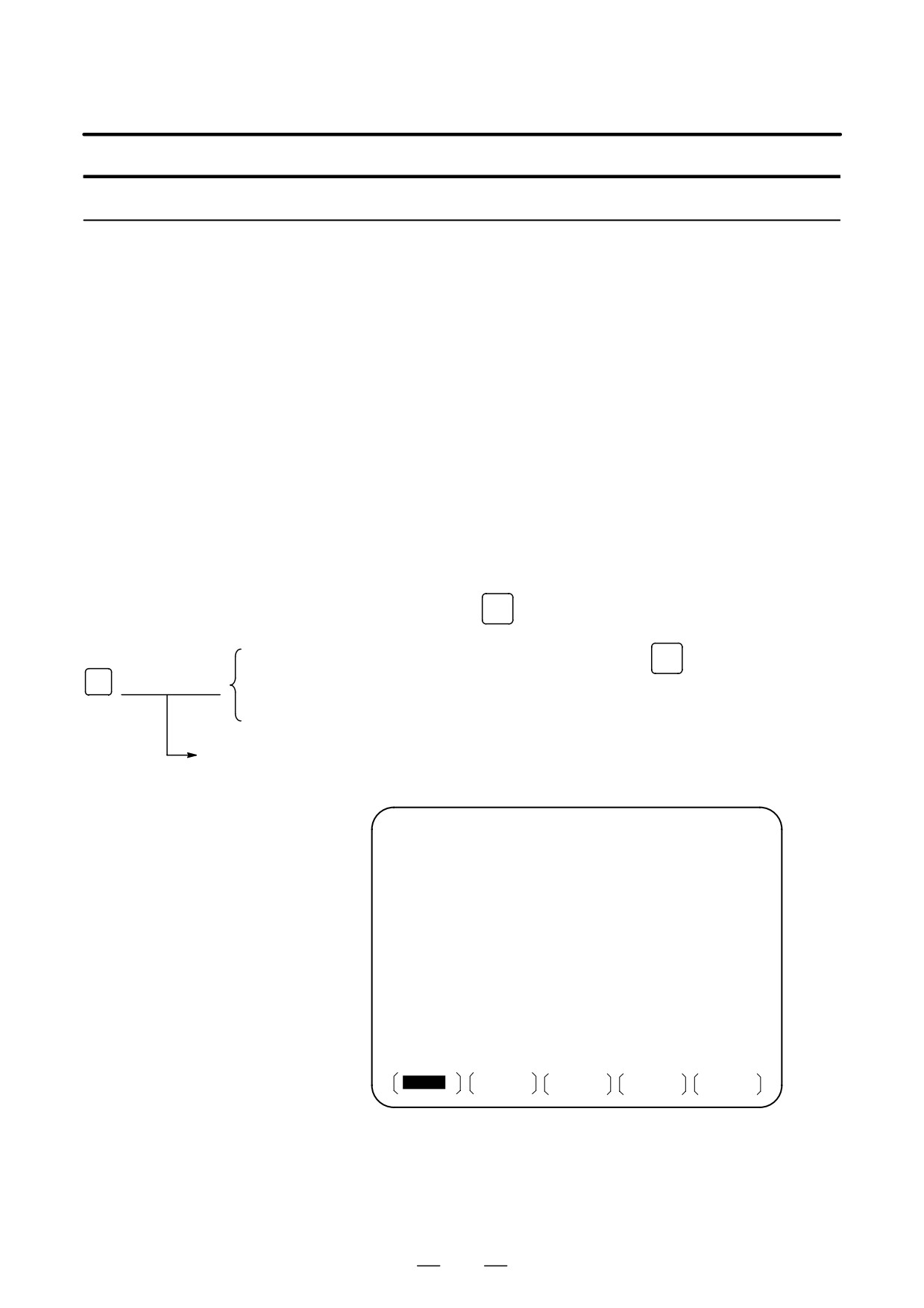
Procedure for Program Restart by Specifying a Block Number
Procedure 1
[ P TYPE ]
1
Retract the tool and replace it with a new one. When necessary,
change the offset.
(Go to step 2.)
[ Q TYPE ]
1
When power is turned ON or emergency stop is released, perform all
necessary operations at that time, including the reference position
return.
2
Move the machine manually to the program starting point (machining
start point), and keep the modal data and coordinate system in the
same conditions as at the machining start.
3
If necessary, modify the offset amount.
Procedure 2
[COMMON TO P TYPE /
1
Turn the program restart switch on the machine operator’s panel ON.
Q TYPE]
2
Press function
PROG
key to display the desired program.
[Q TYPE]
3
Find the program head. Press function
RESET
key.
B
or
f f f f f f f f
4
Enter the number of the block to be restarted then press the [P TYPE]
[P TYPE]
or [Q TYPE] soft key. The block number cannot exceed eight digits.
Block number
5
The block number is searched for, and the program restart screen
appears on the display.
PROGRAM RESTART
O0002 N01000
BC : 00000002
DESTINATION
M
1
2
X
57. 096
1
2
Z
56. 943
1
2
1
2
1
2
1
* * * * * * * *
DISTANCE TO GO
* * * * * * * *
* * * * * * * *
1 X
1. 459
T * * * * * * * *
* * * * * * * *
2 Z
7. 320
S * * * * *
S
0 T0000
MEM * * * *
* * *
* * *
10 : 10 : 40
RSTR
FL.SDL
(OPRT)
DESTINATION shows the position at which machining is to restart.
DISTANCE TO GO shows the distance from the current tool position
to the position where machining is to restart. A number to the left of
each axis name indicates the order of axes (determined by parameter
setting) along which the tool moves to the restart position.
523
4. AUTOMATIC OPERATION
OPERATION
B-63524EN/01
The coordinates and amount of travel for restarting the program can
be displayed for up to five axes. If your system supports six or more
axes, pressing the [RSTR] soft key again displays the data for the
sixth and subsequent axes. (The program restart screen displays only
the data for CNC-controlled axes.)
M: Fourteen most recently specified M codes
T: Two most recently specified T codes
S: Most recently specified S code
B: Most recently specified B code
Codes are displayed in the order in which they are specified. All
codes are cleared by a program restart command or cycle start in the
reset state.
6
Turn the program re-start switch OFF. At this time, the figure at the
left side of axis name DISTANCE TO GO blinks.
7
Check the screen for the M, S, T, and B codes to be executed. If they
are found, enter the MDI mode, then execute the M, S, T, and B
functions. After execution, restore the previous mode.
These codes are not displayed on the program restart screen.
8
Check that the distance indicated under DISTANCE TO GO is correct.
Also check whether there is the possibility that the tool might hit a
workpiece or other objects when it moves to the machining restart
position. If such a possibility exists, move the tool manually to a
position from which the tool can move to the machining restart
position without encountering any obstacles.
9
Press the cycle start button. The tool moves to the machining restart
position at the dry run feedrate sequentially along axes in the order
specified by parameter settings (No. 7310). Machining is then
restarted.
Explanations
D Block number
When the CNC is stopped, the number of executed blocks is displayed on
the program screen or program restart screen. The operator can specify
the number of the block from which the program is to be restarted, by
referencing the number displayed. The displayed number indicates the
number of the block that was executed most recently. For example, to
restart the program from the block at which execution stopped, specify the
displayed number, plus one.
The number of blocks is counted from the start of machining, assuming
one NC line of a CNC program to be one block.
< Example 1 >
CNC Program
Number of blocks
O 0001 ;
1
G90 G92 X0 Y0 Z0 ;
2
G01 X100. F100 ;
3
G03 X01 -50. F50 ;
4
M30 ;
5
524
B-63524EN/01
OPERATION
4. AUTOMATIC OPERATION
< Example 2 >
CNC Program
Number of blocks
O 0001 ;
1
G90 G92 X0 Y0 Z0 ;
2
G90 G00 Z100. ;
3
G81 X100. Y0. Z-120. R-80. F50. ;
4
#1 = #1 + 1 ;
4
#2 = #2 + 1 ;
4
#3 = #3 + 1 ;
4
G00 X0 Z0 ;
5
M30 ;
6
Macro statements are not counted as blocks.
D Storing / clearing the
The block number is held in memory while no power is supplied. The
block number
number can be cleared by cycle start in the reset state.
D Block number when a
The program screen usually displays the number of the block currently
program is halted or
being executed. When the execution of a block is completed, the CNC
stopped
is reset, or the program is executed in single-block stop mode, the
program screen displays the number of the program that was executed
most recently.
When a CNC program is halted or stopped by feed hold, reset, or
single-block stop, the following block numbers are displayed:
Feed hold : Block being executed
Reset : Block executed most recently
Single-block stop : Block executed most recently
For example, when the CNC is reset during the execution of block 10, the
displayed block number changes from 10 to 9.
D MDI intervention
When MDI intervention is performed while the program is stopped by
single-block stop, the CNC commands used for intervention are not
counted as a block.
D Block number exceeding
When the block number displayed on the program screen exceeds eight
eight digits
digits, the block number is reset to 0 and counting continues.
Limitation
D P-type restart
Under any of the following conditions, P-type restart cannot be
performed:
D When automatic operation has not been performed since the power
was turned on
D When automatic operation has not been performed since an emergency
stop was released
D When automatic operation has not been performed since the
coordinate system was changed or shifted (change in an external offset
from the workpiece reference point)
D Restart block
The block to be restarted need not be the block which was interrupted;
operation can restart with any block. When P-type restart is performed,
the restart block must use the same coordinate system as when operation
was interrupted.
525
4. AUTOMATIC OPERATION
OPERATION
B-63524EN/01
D Single block
When single block operation is ON during movement to the restart
position, operation stops every time the tool completes movement along
an axis. When operation is stopped in the single block mode, MDI
intervention cannot be performed.
D Manual intervention
During movement to the restart position, manual intervention can be used
to perform a return operation for an axis if it has not yet been performed
for the axis. A return operation cannot be done further on axes for which
a return has already been completed.
D Reset
Never reset during the time from the start of a search at restart until
machining is restarted. Otherwise, restart must be performed again from
the first step.
D Manual absolute
Regardless of whether machining has started or not, manual operation
must be performed when the manual absolute mode is on.
D Reference position
If no absolute-position detector (absolute pulse coder) is provided, be
return
sure to perform reference position return after turning on the power and
before performing restart.
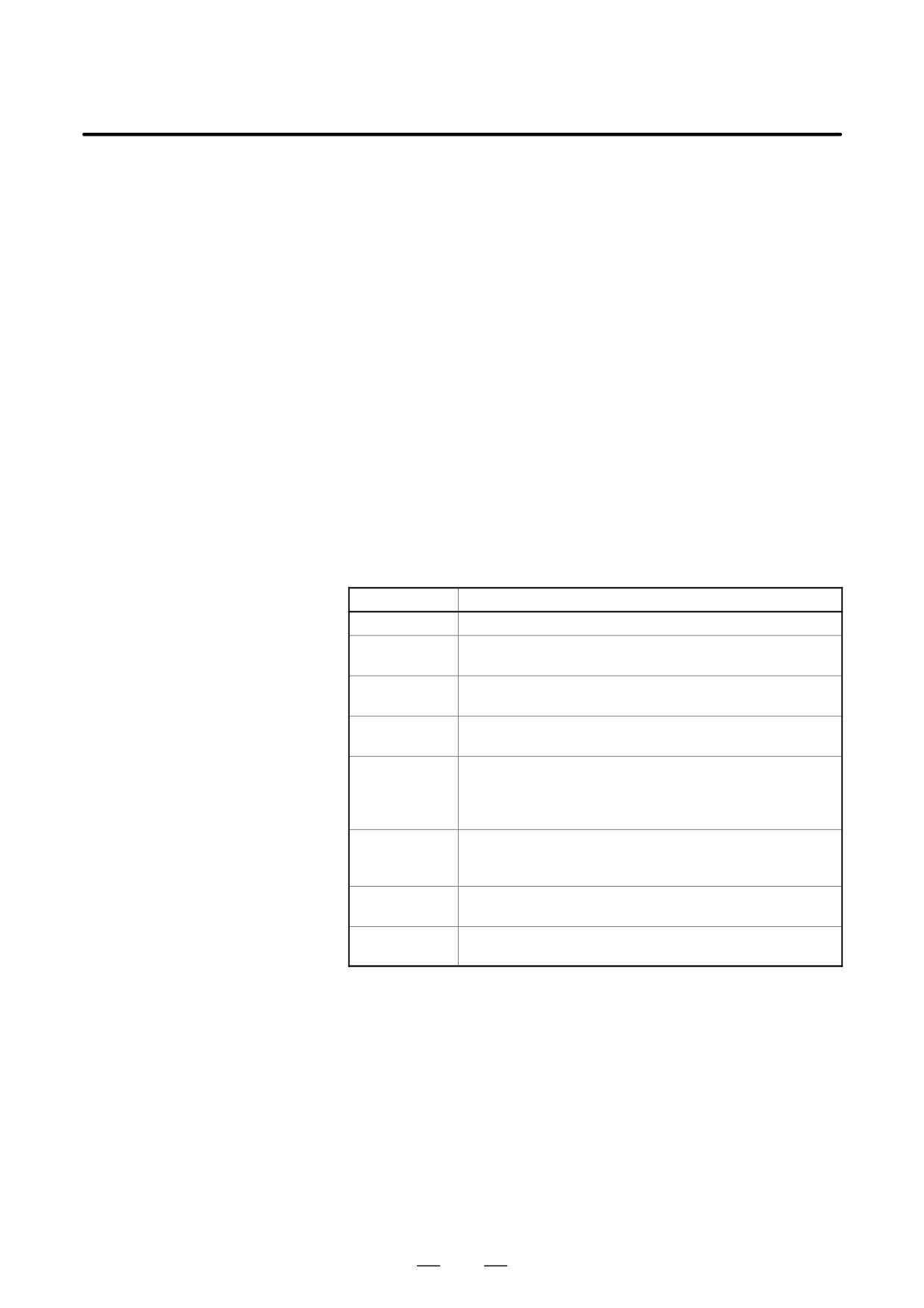
Alarm
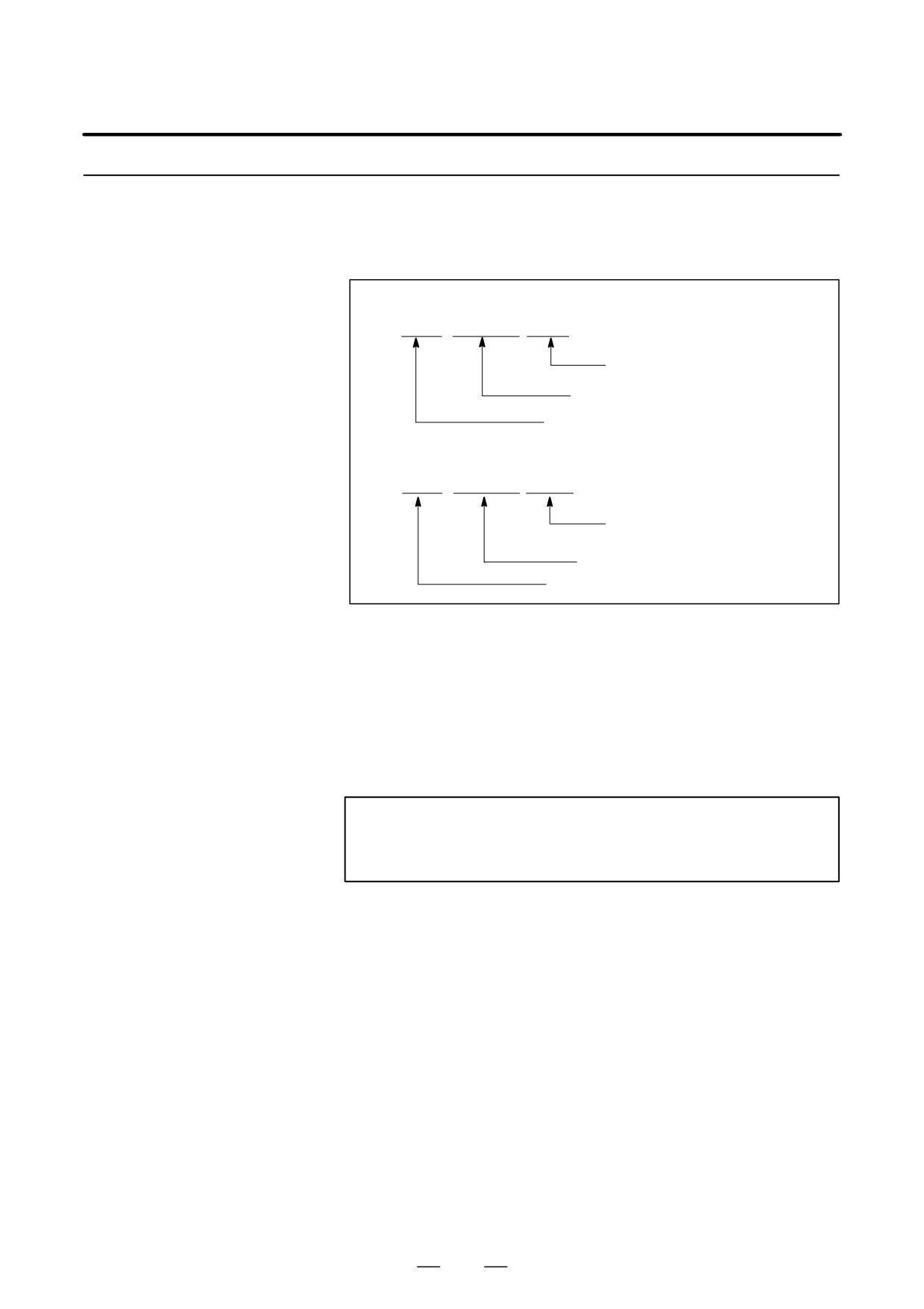
Alarm No.
Contents
071
The specified block number for restarting the program is not found.
094
After interruption, a coordinate system was set, then P-type
restart was specified.
095
After interruption, the coordinate system shift was changed,
then P-type restart was specified.
096
After interruption, the coordinate system was changed, then
P-type restart was specified.
097
When automatic operation has not been performed since
the power was turned on, emergency stop was released, or
P/S alarm (Nos. 094 to 097) was reset, P-type restart was
specified.
098
After the power was turned on, restart operation was per-
formed without reference position return, but a G28 com-
mand was found in the program.
099
A move command was specified from the MDI panel during
a restart operation.
5020
An erroneous parameter was specififed for restarting a pro-
gram.
526

B-63524EN/01
OPERATION
4. AUTOMATIC OPERATION
WARNING
As a rule, the tool cannot be returned to a correct position
under the following conditions.
S Special care must be taken in the following cases since
none of them cause an alarm:
S Manual operation is performed when the manual absolute
mode is OFF.
S Manual operation is performed when the machine is locked.
S When the mirror image is used.
S When manual operation is performed in the course of axis
movement for returning operation.
S When the program restart is commanded for a block
between the block for skip cutting and subsequent absolute
command block.
S When program restart specified for an intermediate block for
a multiple repetitive canned cycle.
527
4. AUTOMATIC OPERATION
OPERATION
B-63524EN/01
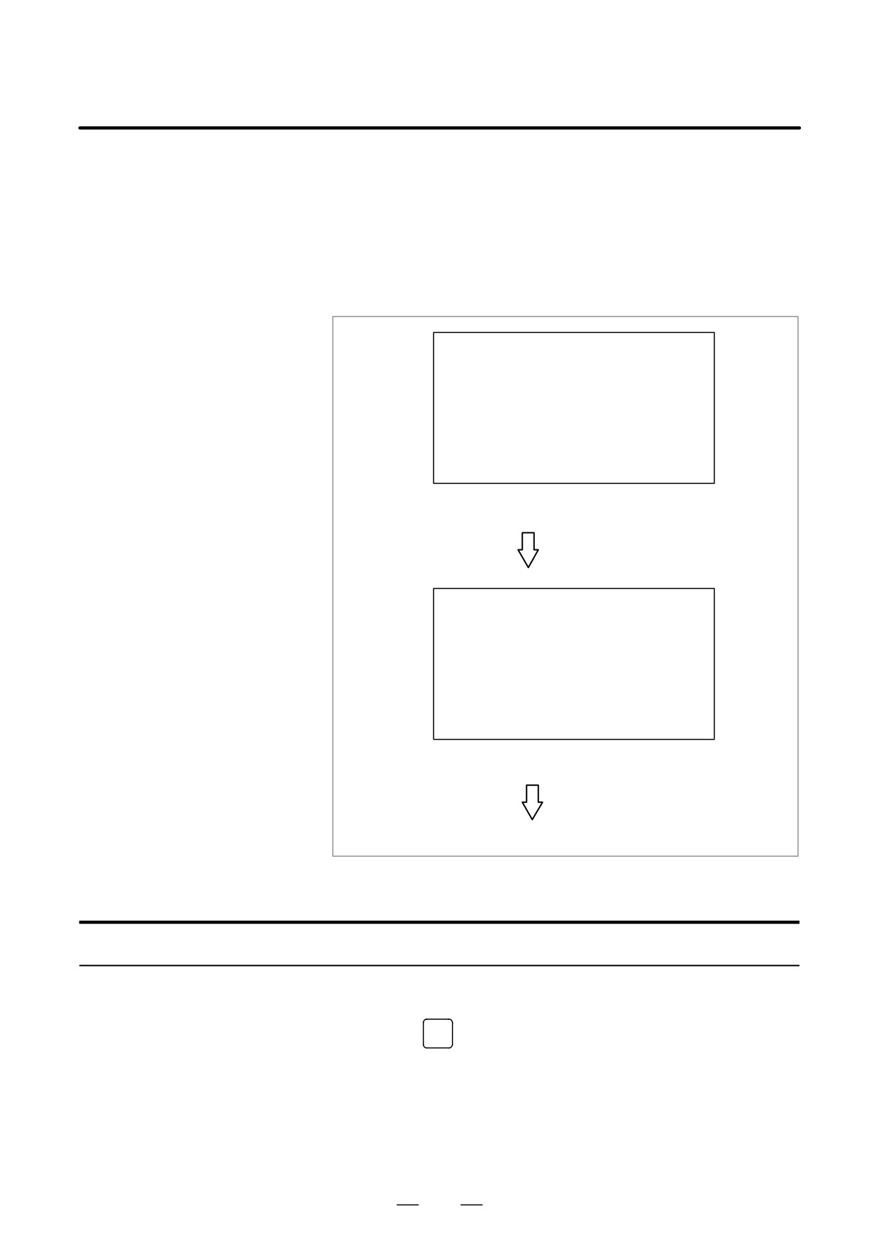
The schedule function allows the operator to select files (programs)
4.4
registered on a floppy-disk in an external input/output device (Handy
SCHEDULING
File, Floppy Cassette, or FA Card) and specify the execution order and
FUNCTION
number of repetitions (scheduling) for performing automatic operation.
It is also possible to select only one file from the files in the external
input/output device and execute it during automatic operation.
FILE DIRECTORY
FILE NO. FILE NAME
0001
O0010
0002
O0020
0003
O0030
0004
O0040
List of files in an external input/output device
Set file number and
number of repetitions.
ORDER FILE NO REPETITION
01
0002
2
02
0003
1
03
0004
3
04
0001
2
Scheduling screen
Executing automatic operation
Procedure for Scheduling Function
⋅Procedure for executing
1
Press the MEMORY switch on the machine operator’s panel, then
one file
PROG
press the
function key on the MDI panel.
2
Press the rightmost soft key (continuous menu key), then press the
[FL. SDL] soft key. A list of files registered in the Floppy Cassette is
displayed on screen No. 1. To display more files that are not
displayed on this screen, press the page key on the MDI panel. Files
registered in the Floppy Cassette can also be displayed successively.
528
B-63524EN/01
OPERATION
4. AUTOMATIC OPERATION
FILE DIRECTORY
O0001 N00000
CURRENT SELECTED : SCHEDULE
NO. FILE NAME
(METER) VOL
0000 SCHEDULE
0001 PARAMETER
58.5
0002 ALL PROGRAM
11.0
0003 O0001
1.9
0004 O0002
1.9
0005 O0010
1.9
0006 O0020
1.9
0007 O0040
1.9
0008 O0050
1.9
MEM * * * *
* * *
* * *
19 : 14 : 47
PRGRM
DIR
SCHDUL
(OPRT)
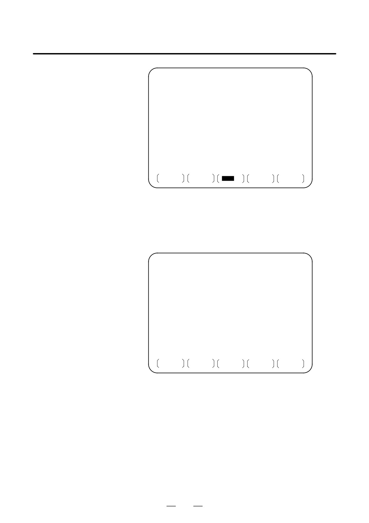
Screen No. 1
3
Press the [(OPRT)] and [SELECT] soft keys to display “SELECT
FILE NO.” (on screen No. 2). Enter a file number, then press the [F
SET] and [EXEC] soft keys. The file for the entered file number is
selected, and the file name is indicated after
“CURRENT
SELECTED:”.
FILE DIRECTORY
O0001 N00000
CURRENT SELECTED:O0040
NO. FILE NAME
(METER) VOL
0000 SCHEDULE
0001 PARAMETER
58.5
0002 ALL PROGRAM
11.0
0003 O0001
1.9
0004 O0002
1.9
0005 O0010
1.9
0006 O0020
1.9
0007 O0040
1.9
0008 O0050
1.9
SELECT FILE NO.=7
>_
MEM * * * *
* * *
* * *
19 : 17 : 10
F SET
EXEC
Screen No. 2
4
Press the REMOTE switch on the machine operator’s panel to enter
the RMT mode, then press the cycle start switch. The selected file is
executed. For details on the REMOTE switch, refer to the manual
supplied by the machine tool builder. The selected file number is
indicated at the upper right corner of the screen as an F number
(instead of an O number).
529
4. AUTOMATIC OPERATION
OPERATION
B-63524EN/01
FILE DIRECTORY
F0007 N00000
CURRENT SELECTED:O0040
RMT
* * * *
* * *
* * *
13 : 27 : 54
PRGRM
DIR
SCHDUL
(OPRT)
Screen No. 3
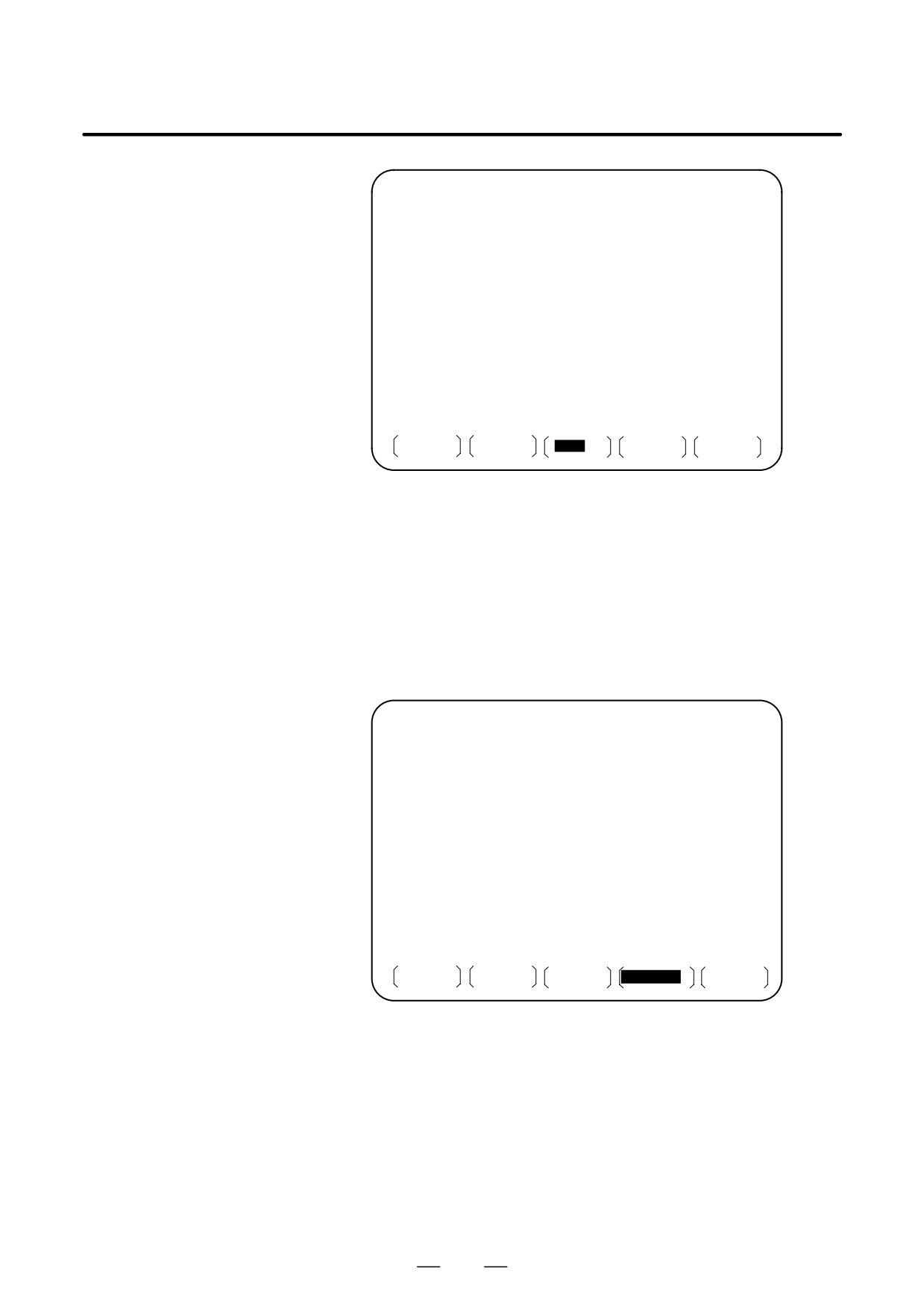
D Procedure for executing
1
Display the list of files registered in the Floppy Cassette. The display
the scheduling function
procedure is the same as in steps 1 and 2 for executing one file.
2
On screen No. 2, press the [(OPRT)] and [SELECT] soft keys to
display “SELECT FILE NO.”
3
Enter file number 0, and press the [F SET], and [EXEC] soft keys.
“SCHEDULE” is indicated after “CURRENT SELECTED:”.
4
Press the left most soft key (return menu key) and the [SCHDUL] soft
key. Screen No. 4 appears.
FILE DIRECTORY
F0000 N02000
ORDER FILE NO.
REQ.REP CUR.REP
01
02
03
04
05
06
07
08
09
10
>_
MEM * * * *
* * *
* * *
22 : 07 : 00
PRGRM
DIR
SCHDUL
(OPRT)
Screen No. 4
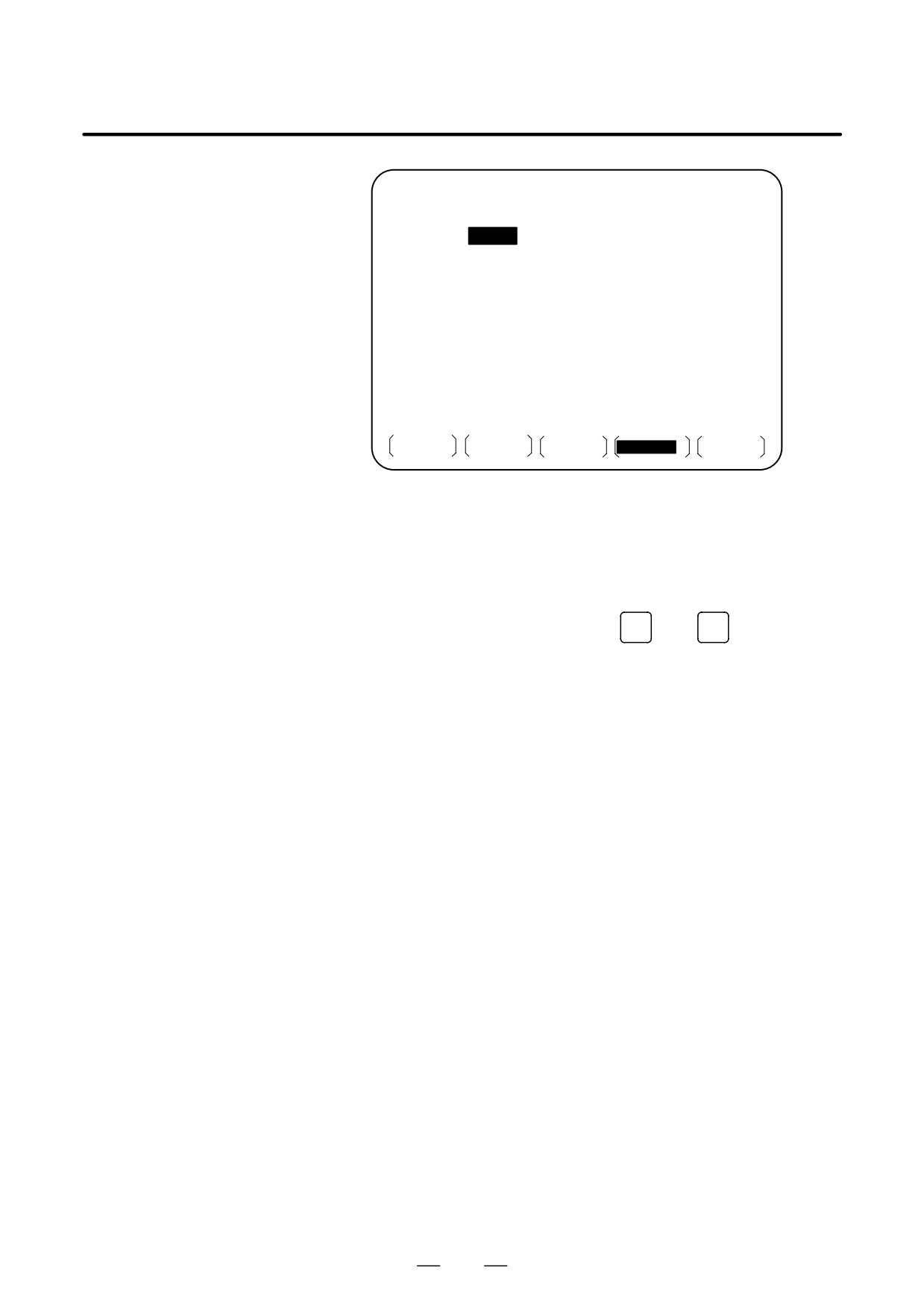
Move the cursor and enter the file numbers and number of repetitions
in the order in which to execute the files. At this time, the current
number of repetitions “CUR.REP” is 0.
5
Press the REMOTE switch on the machine operator’s panel to enter
the RMT mode, then press the start switch. The files are executed in
the specified order. When a file is being executed, the cursor is
positioned at the number of that file.
The current number of repetitions CUR.REP is increased when M02
or M30 is executed in the program being run.
530
B-63524EN/01
OPERATION
4. AUTOMATIC OPERATION
FILE DIRECTORY
O0000 N02000
ORDER
FILE NO.
REQ.REP
CUR.REP
01
0007
5
5
02
0003
23
23
03
0004
9999
156
04
0005
LOOP
0
05
06
07
08
09
10
RMT
* * * *
* * *
* * *
10 : 10 : 40
PRGRM
DIR
SCHDUL
(OPRT)
Screen No. 5
Explanations
D Specifying no file
If no file number is specified on screen No. 4 (the file number field is left
number
blank), program execution is stopped at that point. To leave the file
number field blank, press numeric key
0
then
INPUT
D Endless repetition
If a negative value is set as the number of repetitions, <LOOP> is
displayed, and the file is repeated indefinitely.
D Clear
When the [(OPRT)], [CLEAR], and [EXEC] soft keys are pressed on
screen No. 4, all data is cleared. However, these keys do not function
while a file is being executed.
D Return to the program
When the [PRGRM] soft key is pressed on screen No. 1, 2, 3, 4, or 5, the
screen
program screen is displayed.
Limitation
D Number of repetitions
Up to 9999 can be specified as the number of repetitions. If 0 is set for a
file, the file becomes invalid and is not executed.
D Number of files
By pressing the page key on screen No. 4, up to 20 files can be registered.
registered
D M code
When M codes other than M02 and M30 are executed in a program, the
current number of repetitions is not increased.
D Displaying the floppy
During the execution of file, the floppy directory display of background
disk directory during file
editing cannot be referenced.
execution
D Restarting automatic
To resume automatic operation after it is suspended for scheduled
operation
operation, press the reset button.
D Scheduling function for
The scheduling function can be used only for a single tool post.
the two-path control
531

4. AUTOMATIC OPERATION
OPERATION
B-63524EN/01
Alarm
Alarm No.
Description
086
An attempt was made to execute a file that was not regis-
tered in the floppy disk.
210
M198 and M99 were executed during scheduled operation,
or M198 was executed during DNC operation.
532
B-63524EN/01
OPERATION
4. AUTOMATIC OPERATION
The subprogram call function is provided to call and execute subprogram
4.5
files stored in an external input/output device (Handy File, FLOPPY
SUBPROGRAM CALL
CASSETTE, FA Card) during memory operation.
FUNCTION (M198)
When the following block in a program in CNC memory is executed, a
subprogram file in the external input/output device is called:
To use this function, the Floppy Cassette directory display option must
be installed.
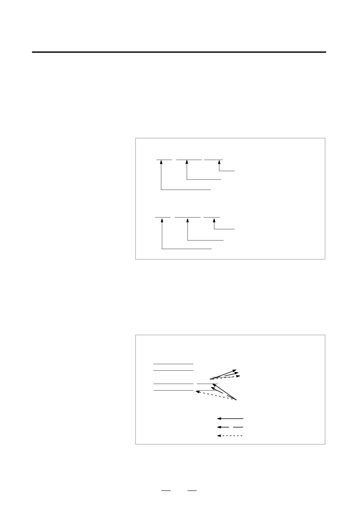
Format
1. FS15 tape format
M198 Pffff L∆∆∆∆ ;
Number of repetitions
File number for a file in the I/O device
I/O devices call instruction
2. Other than FS15 tape format
M198 Pffff ∆∆∆∆ ;
File number for a file
in the I/O device
Number of repetitions
I/O devices call instruction
Explanation
The subprogram call function is enabled when parameter No. 0102 for the
input/output device is set to 3. When the custom macro option is
provided, either format 1 or 2 can be used. A different M code can be used
for a subprogram call depending on the setting of parameter No. 6030.
In this case, M198 is executed as a normal M code. The file number is
specified at address P. If the SBP bit (bit 2) of parameter No. 3404 is set
to 1, a program number can be specified. When a file number is specified
at address P, Fxxxx is indicated instead of Oxxxx.
Programs in memory
Program in the external
execution mode
input/output device
N1
;
N2
;
0123
File number
N3 M198 P0003 0123 ;
N4
;
N5
;
: First call/return
: Second call/return
: Third call/return
Fig. 4.5 Program Flow When M198 is Specified
Restrictions
For the two-path control, subprograms in a floppy cassette cannot be
called for the two tool posts at the same time.
533
4. AUTOMATIC OPERATION
OPERATION
B-63524EN/01
NOTE
1
When M198 in the program of the file saved in a floppy
cassette is executed, a P/S alarm (No.210) is given. When
a program in the memory of CNC is called and M198 is
executed during execution of a program of the file saved in
a floppy cassette, M198 is changed to an ordinary M-code.
2
When MDI is intervened and M198 is executed after M198
is commanded in the memory mode, M198 is changed to an
ordinary M-code. When the reset operation is done in the
MDI mode after M198 is commanded in the MEMORY
mode, it does not influence on the memory operation and
the operation is continued by restarting it in the MEMORY
mode.
534
B-63524EN/01
OPERATION
4. AUTOMATIC OPERATION
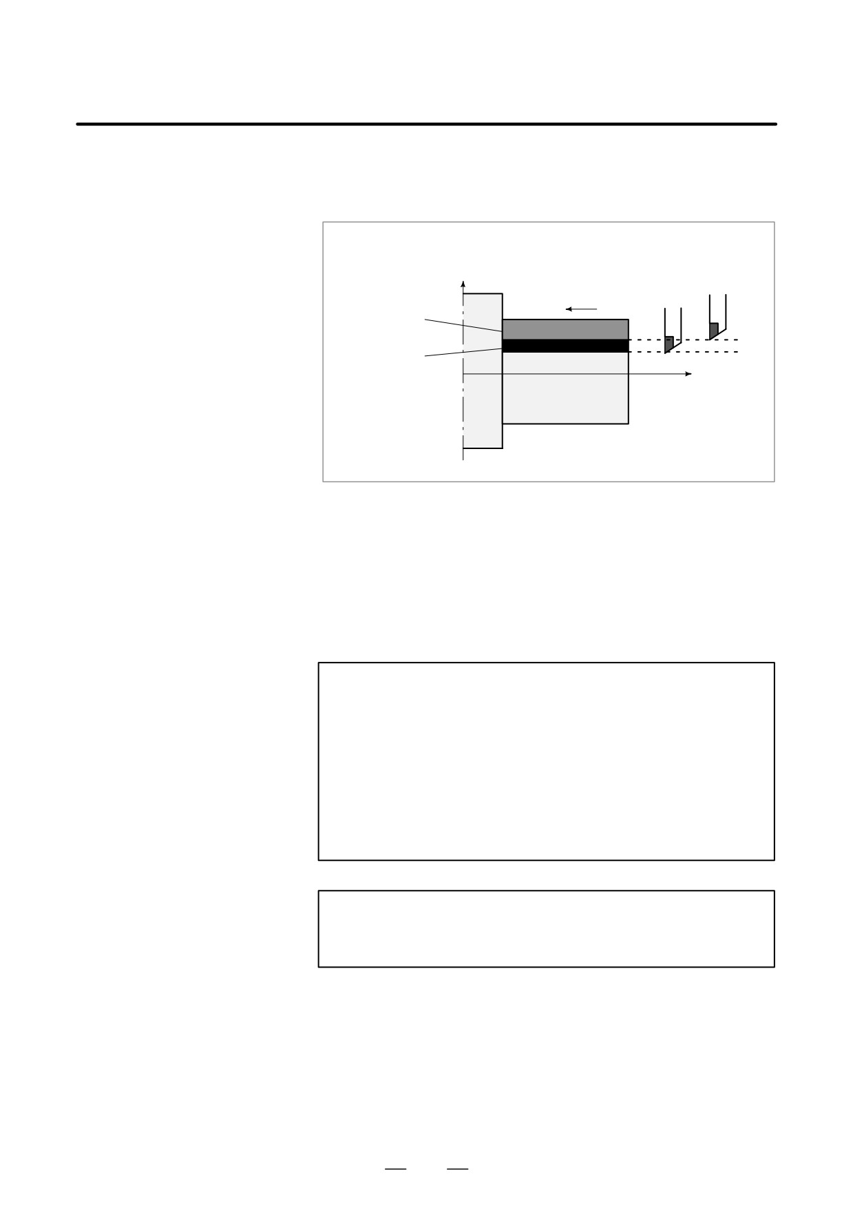
The movement by manual handle operation can be done by overlapping
4.6
it with the movement by automatic operation in the automatic operation
MANUAL HANDLE
mode.
INTERRUPTION
Tool position during
automatic operation
X
Tool position after
handle interruption
Programmed
depth of cut
Depth of cut by
handle interruption
Z
Workpiece
Fig. 4.6 Manual Handle Interruption
D Handle interruption axis selection signals
For the handle interruption axis selection signals, refer to the manual
supplied by the machine tool builder.
During automatic operation, handle interruption is enabled for an axis if
the handle interruption axis selection signal for that axis is on. Handle
interruption is performed by turning the handle of the manual pulse
generator.
WARNING
The travel distance by handle interruption is determined
according to the amount by which the manual pulse
generator is turned and the handle feed magnification (
1,
10, M, N).
Since this movement is not accelerated or decelerated, it is
very dangerous to use a large magnification value for
handle interruption.
The move amount per scale at
1 magnification is 0.001
mm (metric output) or 0.0001 inch (inch output).
NOTE
Handle interruption is disabled when the machine is locked
during automatic operation.
535
4. AUTOMATIC OPERATION
OPERATION
B-63524EN/01
Explanations
D Relation with other
The following table indicates the relation between other functions and the
functions
movement by handle interrupt.
Display
Relation
Machine lock is effective. The tool does not move
Machine lock
even when this signal turns on.
Interlock is effective. The tool does not move even
Interlock
when this signal turns on.
Mirror image is not effective. Interrupt functions on the
Mirror image
plus direction by plus direction command, even if this
signal turns on.
D Position display
The following table shows the relation between various position display
data and the movement by handle interrupt.
Display
Relation
Absolute coordinate
Handle interruption does not change absolute coordi-
value
nates.
Relative coordinate
Handle interruption does not change relative coordi-
value
nates.
Machine coordinate
Machine coordinates are changed by the travel dis-
value
tance specified by handle interruption.
D Travel distance display
Press the function key
POS
, then press the chapter selection soft key
[HNDL].
The move amount by the handle interrupt is displayed. The following 4
kinds of data are displayed concurrently.
HANDLE INTERRUPTION
O0000 N00200
(INPUT UNIT)
(OUTPUT UNIT)
X
69.594
X 69.594
Z -61.439
Z -61.439
(RELATIVE)
(DISTANCE TO GO)
U 0.000
X 0.000
W0.000
Z 0.000
PART COUNT
287
RUN TIME
1H 12M CYCLE TIME
0H 0M 0S
MDI
* * * *
* * *
* * *
10 : 29 : 51
ABS
REL
ALL
HNDL
(OPRT)
(a) INPUT UNIT :
Handle interrupt move amount in input unit system
Indicates the travel distance specified by handle interruption
according to the least input increment.
(b) OUTPUT UNIT :
Handle interrupt move amount in output unit system
Indicates the travel distance specified by handlei nterruption
according to the least command increment.
536
B-63524EN/01
OPERATION
4. AUTOMATIC OPERATION
(c) RELATIVE :
Position in relative coordinate system
These values have no effect on the travel distance specified by handle
interruption.
(d) DISTANCE TO GO :
The remaining travel distance in the current block has no effect on the
travel distance specified by handle interruption.
The handle interrupt move amount is cleared when the manual reference
position return ends every axis.
D Display for five-axis
Systems having five or more axes provide the same display as the overall
systems or better
position display. See III-11.1.3.
537
4. AUTOMATIC OPERATION
OPERATION
B-63524EN/01
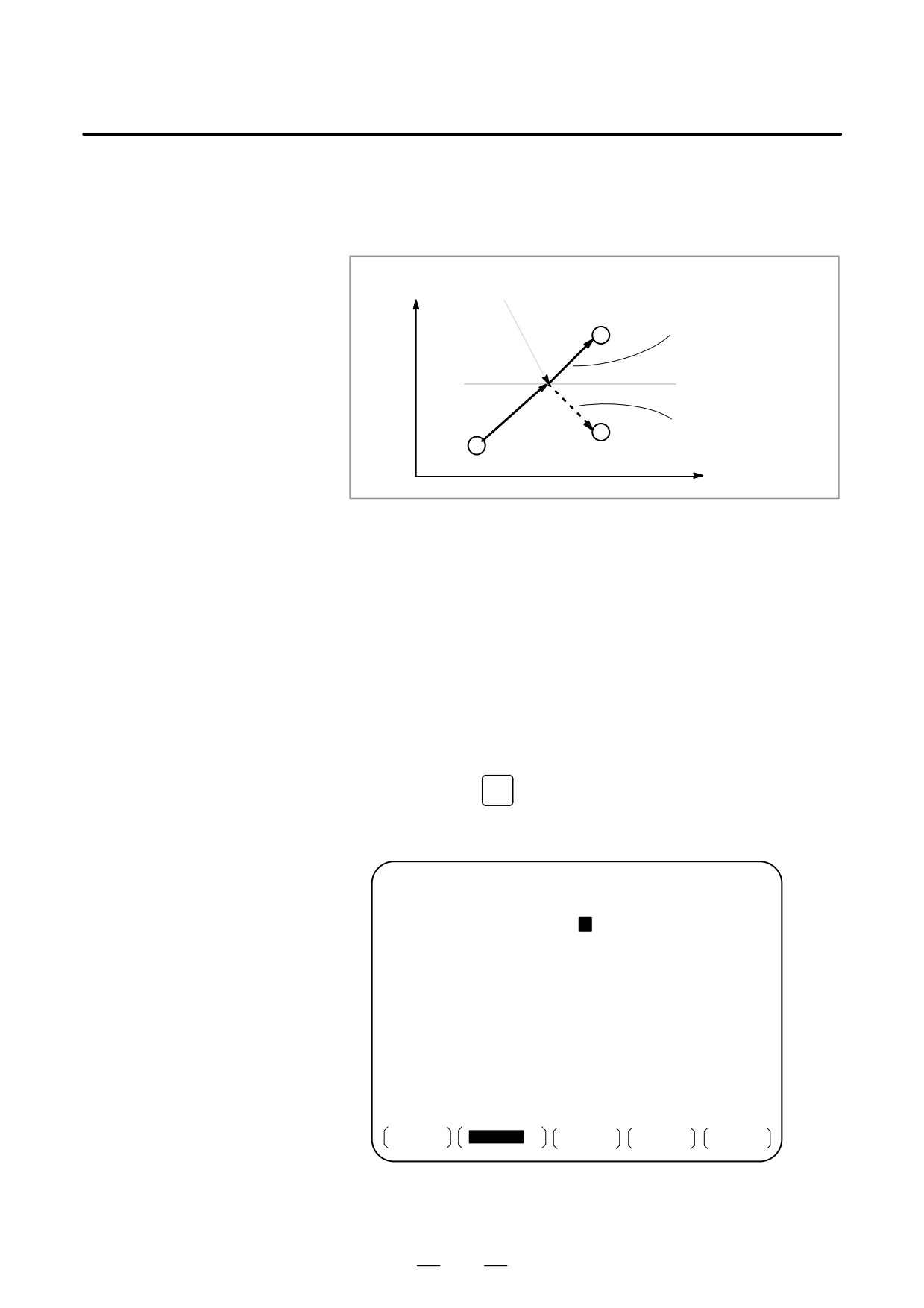
During automatic operation, the mirror image function can be used for
4.7
movement along an axis. To use this function, set the mirror image switch
MIRROR IMAGE
to ON on the machine operator’s panel, or set the mirror image setting to
ON from the CRT/MDI (or LCD/MDI).
X-axis mirror image goes on.
X
Programmed tool path
Tool path after the mirror
image function is used
Tool
Z
Fig. 4.7 Mirror Image
Procedure
The following procedure is given as an example. For actual operation,
refer to the manual supplied by the machine tool builder.
1
Press the single block switch to stop automatic operation. When the
mirror image function is used from the beginning of operation, this
step is omitted.
2
Press the mirror image switch for the target axis on the machine
operator’s panel.
Alternatively, turn on the mirror image setting by following the steps
below:
2-1 Set the MDI mode.
OFFSET
2-2 Press the
SETTING
function key.
2-3 Press the [SETING] soft key for chapter selection to display the
setting screen.
SETTING (MIRROR IMAGE)
O0020 N00001
MIRROR IMAGE X =
1
(0 : OFF 1 : ON)
MIRROR IMAGE Z = 0 (0 : OFF 1 : OM)
>_
MEM * * * *
* * *
* * *
14 : 47 : 57
OFFSET
SETING
WORK
(OPRT)
2-4 Move the cursor to the mirror image setting position, then set the
target axis to 1.
538
B-63524EN/01
OPERATION
4. AUTOMATIC OPERATION
3
Enter an automatic operation mode (memory mode or MDI mode),
then press the cycle start button to start automatic operation.
Explanations
D The mirror image function can also be turned on and off by setting bit
0 (MIRx) of parameter (No. 0012) to 1 or 0.
D For the mirror image switches, refer to the manual supplied by the
machine tool builder.
Restrictions
The direction of movement during manual operation, the direction of
movement from an intermediate point to the reference position during
automatic reference position return (G28).
539
4. AUTOMATIC OPERATION
OPERATION
B-63524EN/01
In cases such as when tool movement along an axis is stopped by feed hold
4.8
during automatic operation so that manual intervention can be used to
MANUAL
replace the tool: When automatic operation is restarted, this function
INTERVENTION AND
returns the tool to the position where manual intervention was started.
RETURN
To use the conventional program restart function and tool withdrawal and
return function, the switches on the operator’s panel must be used in
conjunction with the MDI keys. This function does not require such
operations.
Explanations
D Manual absolute on/off
In manual absolute off mode, the tool does not return to the stop position,
but instead operates according to the manual absolute on/off function.
D Override
For the return operation, the dry run feedrate is used, and the jog feedrate
override function is enabled.
D Return operation
Return operation is performed according to positioning based on
nonlinear interpolation.
D Single block
If the single block stop switch is on during return operation, the tool stops
at the stop position and restarts movement when the cycle start switch is
pressed.
D Cancellation
If a reset occurs or an alarm is issued during manual intervention or the
return operation, this function is cancelled.
D MDI mode
This function can be used in the MDI mode as well.
Restrictions
D Enabling and disabling
This function is enabled only when the automatic operation hold LED is
manual intervention and
on. When there is no travel distance remaining, this function has no effect
return
even if a feed hold stop is performed with the automatic operation hold
signal *SP (bit 5 of G008).
D Offset
When the tool is replaced using manual intervention for a reason such as
damage, the tool movement cannot be restarted by a changed offset in the
middle of the interrupted block.
D Machine lock, mirror
When performing manual intervention, never use the machine lock,
image, and scaling
mirror image, or scaling functions.
540
B-63524EN/01
OPERATION
4. AUTOMATIC OPERATION
Example
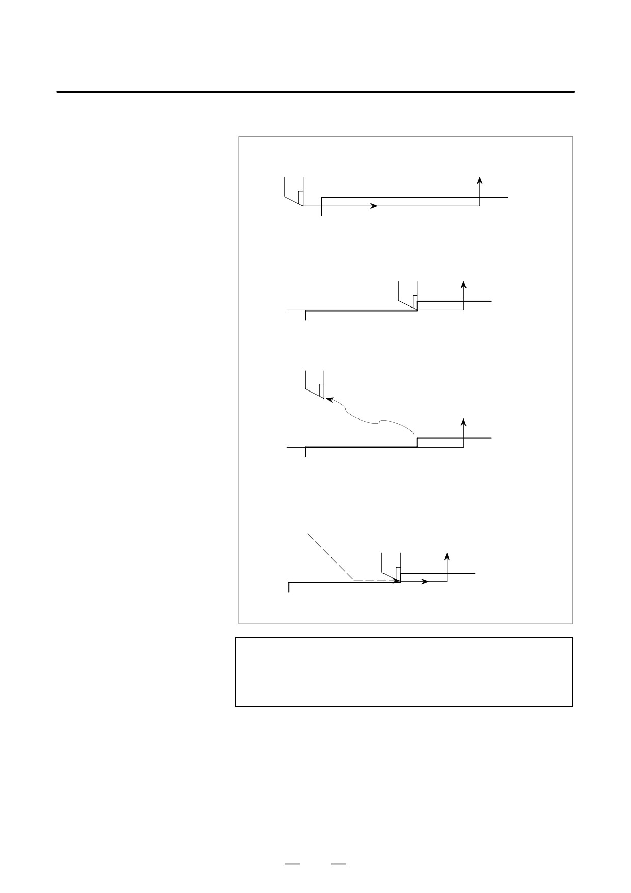
1. The N1 block cuts a workpiece
Tool
N2
Block start point
N1
2. The tool is stopped by pressing the feed hold switch in
the middle of the N1 block (point A).
N2
N1 Point A
3. After retracting the tool manually to point B, tool movement is restarted.
Point B
Manual
intervention
N2
N1 Point A
4. After automatic return to point A at the dry run feedrate, the remaining
move command of the N1 block is executed.
Point B
N2
N1 Point A
WARNING
When performing manual intervention, pay particular
attention of machining and the shape of the workpiece so
that the machine and tool are not damaged.
541
4. AUTOMATIC OPERATION
OPERATION
B-63524EN/01
By activating automatic operation during the DNC operation mode
4.9
(RMT), it is possible to perform machining (DNC operation) while a
DNC OPERATION
program is being read in via reader/puncher interface, or remote buffer.
If the floppy cassette directory display option is available, it is possible
to select files (programs) saved in an external input/output unit of a floppy
format (Handy File, Floppy Cassettes, or FA card) and specify (schedule)
the sequence and frequency of execution for automatic operation.
To use the DNC operation function, it is necessary to set the parameters
related to the reader/punch interface, and remote buffer in advance.
DNC OPERATION
Procedure
1
Search for the program (file) to be executed.
2
Press the REMOTE switch on the machine operator’s panel to set
RMT mode, then press the cycle start switch. The selected file is
executed. For details of the use of the REMOTE switch, refer to the
relevant manual supplied by the machine tool builder.
D Program check screen
(7 soft key type)
PROGRAM CHECK
F0001 N00020
N020 X100.0 Z100.0 (DNC-PROG) ;
N030 X200.0 Z200.0 ;
N050 X400.0 Z400.0 ;
(RELATIVE)
(DIST TO GO) G00 G17 G90
X
100.000 X
0.000 G22 G94 G21
Y
100.000 Y
0.000 G41 G49 G80
Z
0.000 Z
0.000 G98 G50 G67
A
0.000 A
0.000
B
C
0.000 C
0.000 H
M
HD.T
NX.T
D
M
F
S
M
ACT.F
SACT
REPEAT
RMT STRT MTN *** ***
21:20:05
[ ABS
][ REL
][
][
][ (OPRT) ]
D Program screen
(7 soft key type)
PROGRAM
F0001 N00020
N020 X100.0 Z100.0 (DNC-PROG) ;
N030 X200.0 Z200.0 ;
N040 X300.0 Z300.0 ;
N050 X400.0 Z400.0 ;
N060 X500.0 Z500.0 ;
N070 X600.0 Z600.0 ;
N080 X700.0 Z400.0 ;
N090 X800.0 Z400.0 ;
N100 x900.0 z400.0 ;
N110 x1000.0 z1000.0 ;
N120 x800.0 z800.0 ;
RMT STRT MTN *** ***
21:20:05
[
PRGRM
][ CHECK ][
][
][ (OPRT) ]
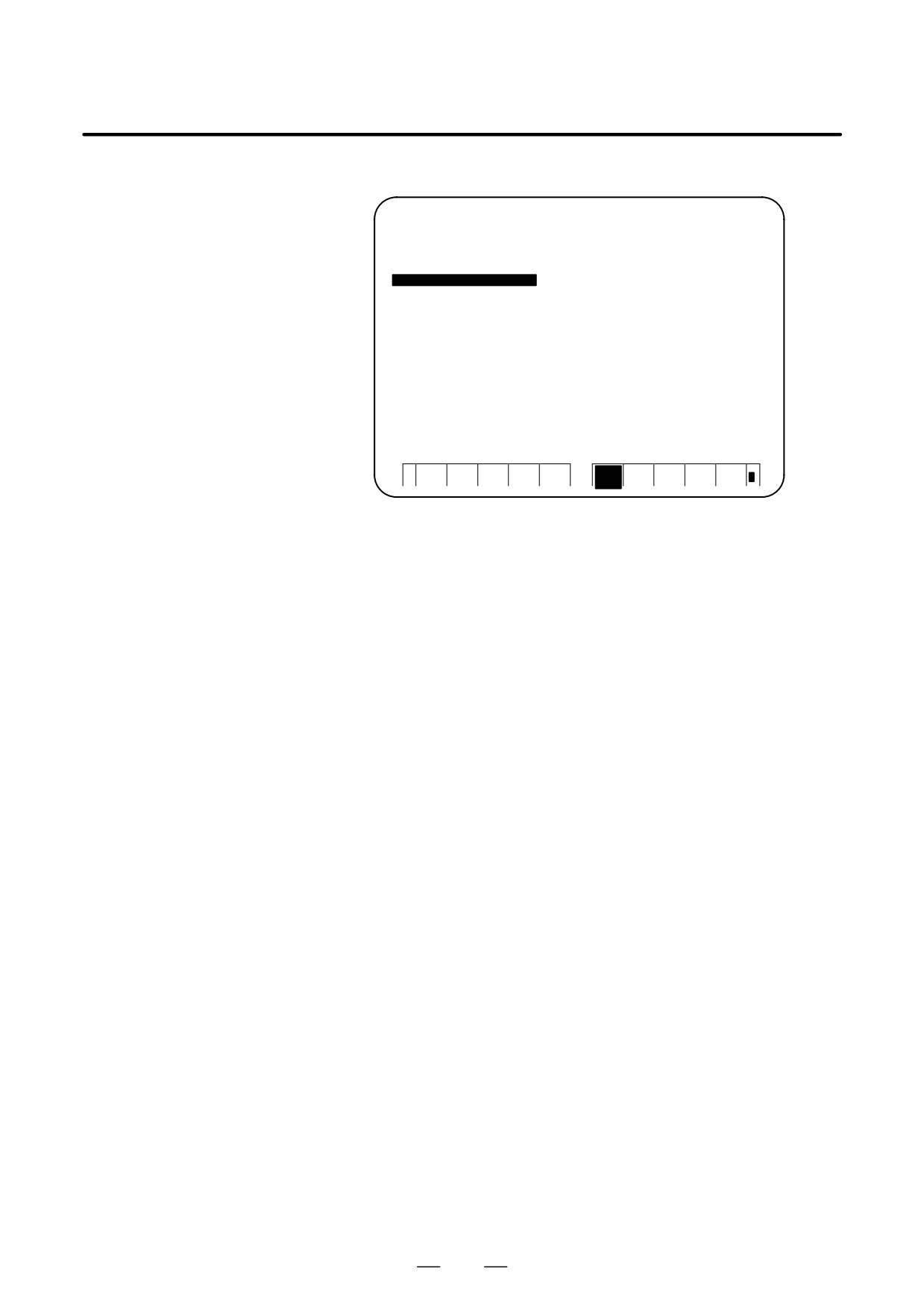
542
B-63524EN/01
OPERATION
4. AUTOMATIC OPERATION
D Program screen
(12 soft key type)
PROGRAM
F0001 N00020
N180 Z50.0 ;
N020 X100.0 (DNC-PROG) ;
N190 Z40.0 ;
N030 X90.0 ;
N200 Z30.0 ;
N040 X80.0 ;
N210 Z20.0 ;
N050 X70.0 ;
N220 Z10.0 ;
N060 X60.0 ;
N230 Z0.0 ;
N070 X50.0 ;
N240 M02 ;
N080 X40.0 ;
%
N090 X30.0 ;
N100 X20.0 ;
N110 X10.0 ;
N120 X0.0 ;
N130 Z100.0 ;
N140 Z90.0 ;
N150 Z80.0 ;
N160 Z70.0 ;
N170 Z60.0 ;
RMT STRT MTN *** *** 22:23:24
PRGR
CHEC
(OPR
+
M
K
T)
During DNC operation, the program currently being executed is
displayed on the program check screen and program screen.
The number of displayed program blocks depends on the program being
executed.
Any comment enclosed between a control-out mark (() and control-in
mark ()) within a block is also displayed.
Explanations
D During DNC operation, programs and macro programs stored in
memory can be called.
Limitations
D Limit on number of
In program display, no more than 256 characters can be displayed.
characters
Accordingly, character display may be truncated in the middle of a block.
D M198 (command for
In DNC operation, M198 cannot be executed. If M198 is executed, P/S
calling a program from
alarm No. 210 is issued.
within an external
input/output unit)
D Custom macro
In DNC operation, custom macros can be specified, but no repeat
instruction and branch instruction can be programmed. If a repeat
instruction or branch instruction is executed, P/S alarm No. 123 is issued.
When reserved words (such as IF, WHILE, COS, and NE) used with
custom macros in DNC operation are displayed during program display,
a blank is inserted between adjacent characters.
Example
[During DNC operation]
#102=SIN[#100] ;
→
#102 = S I N[#100] ;
IF[#100NE0]GOTO5 ;
→
I F[#100NE0] G O T O 5 ;
D M99
When control is returned from a subprogram or macro program to the
calling program during DNC operation, it becomes impossible to use a
return command (M99P****) for which a sequence number is specified.
543
4. AUTOMATIC OPERATION
OPERATION
B-63524EN/01
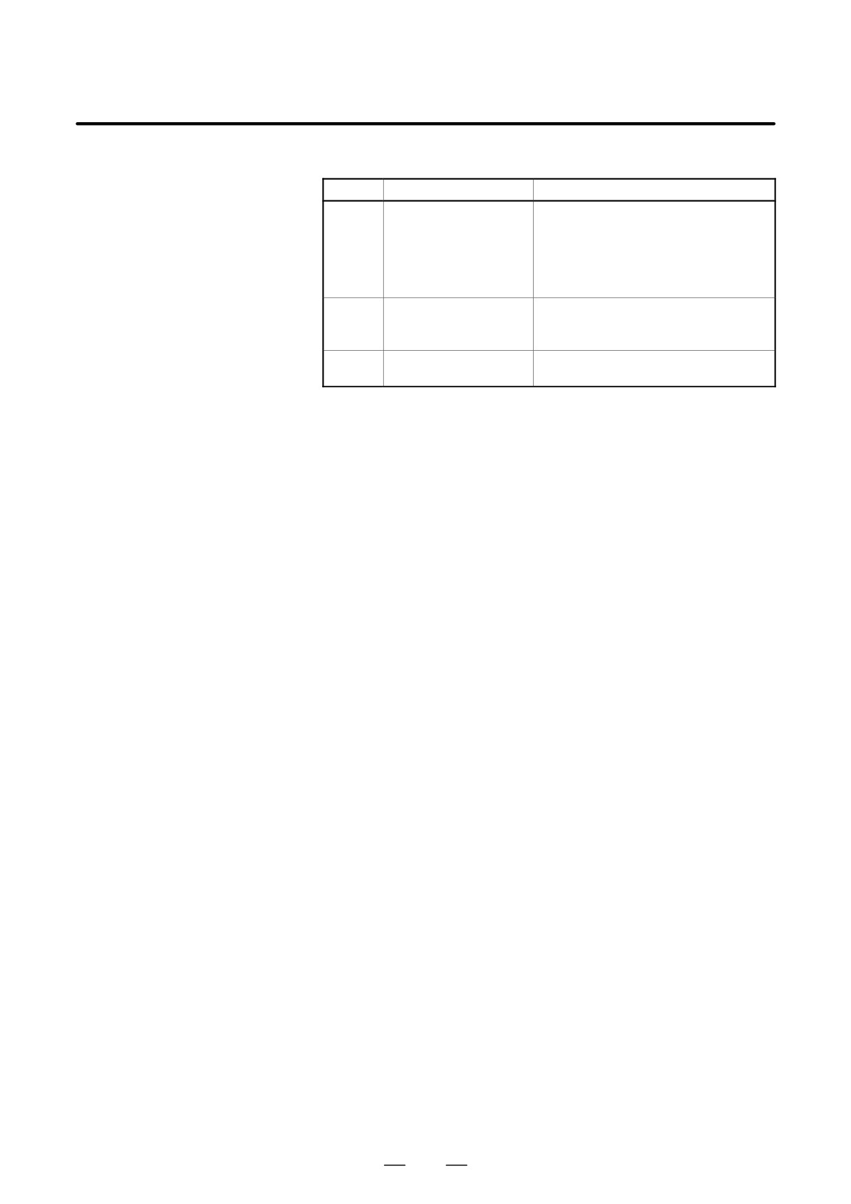
Alarm
Number
Message
Contents
086
DR SIGNAL OFF
When entering data in the memory by
using Reader / Puncher interface, the
ready signal (DR) of reader / puncher
was turned off.
Power supply of I/O unit is off or cable is
not connected or a P.C.B. is defective.
123
CAN NOT USE MACRO
Macro control command is used during
COMMAND IN DNC
DNC operation.
Modify the program.
210
CAN NOT COMAND
Or M198 is executed in the DNC opera-
M198/M199
tion. Modify the program.
544
B-63524EN/01
OPERATION
4. AUTOMATIC OPERATION
4.10
DNC OPERATION
WITH MEMORY
CARD
4.10.1
“DNC operation with Memory Card” is a function that it is possible to
perform machining with executing the program in the memory card,
Specification
which is assembled to the memory card interface, where is the left side
of the screen.
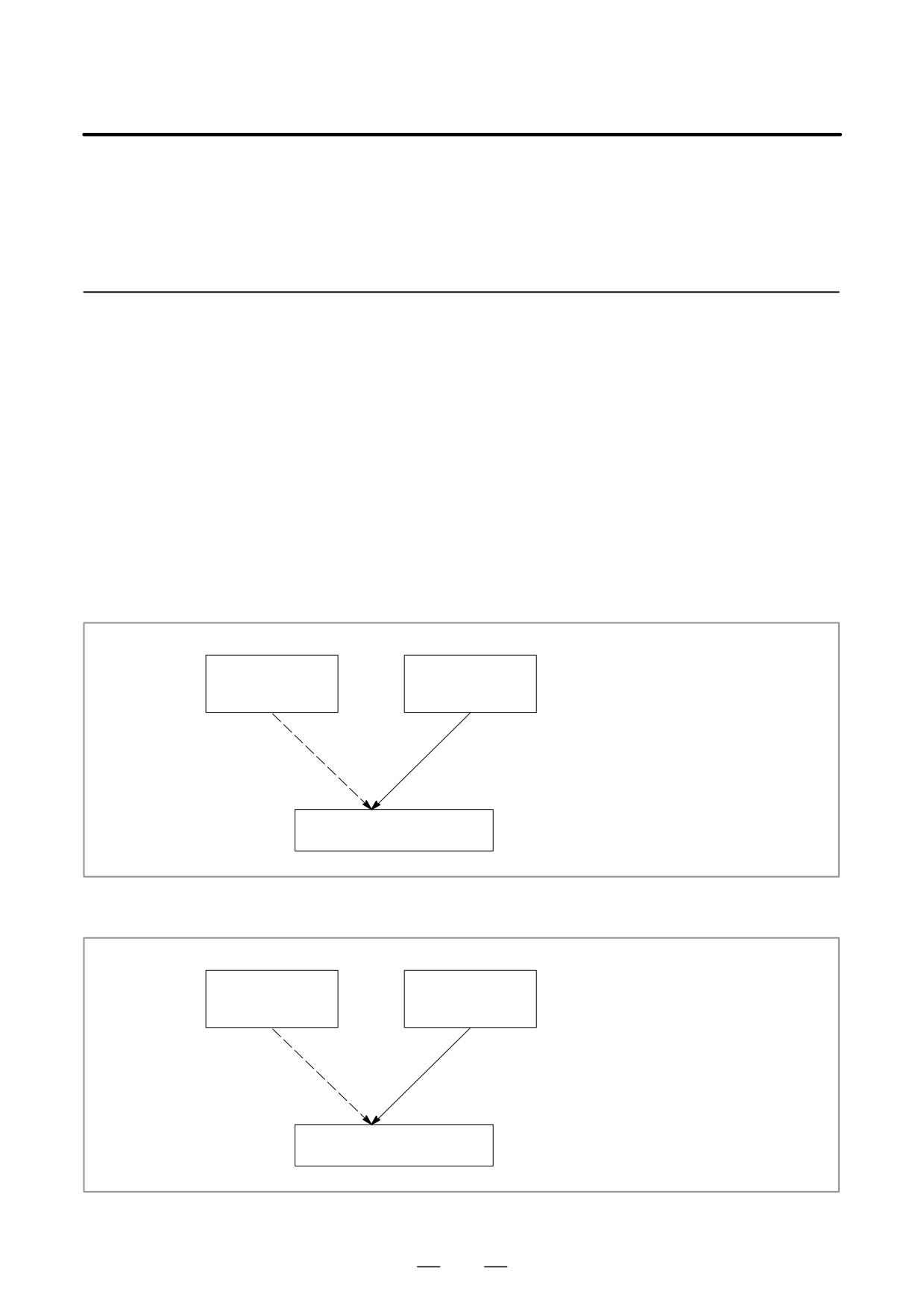
There are two methods to use this function as follows.
(a) By starting automatic operation
(cycle start) during the DNC
operation mode (RMT), it is possible to perform machining (DNC
operation) while a program is being read from a memory card, as by
using the external input/output unit such as a floppy cassette and so on.
(Fig. 4.10.1 (a))
(b) It is possible to read sub-programs written in the memory card and
execute them by the command Subprogram call (M198). (Fig. 4.10.1
(b))
It is possible to do the DNC
Memory in CNC
Memory Card
operation with Memory card
(Program)
(Program)
instead of the normal memory
operation by memory in the CNC.
Normal Memory
DNC operation
operation by
with Memory
memory in the
card
CNC
Execution of programs
Fig. 4.10.1 (a)
It is possible to execute the
Memory in CNC
Memory Card
subprogram in the memory card
(Program)
(Sub Program)
during memory operation.
Normal Memory
Subprogram
operation by memory
Call (M198)
in the CNC
Execution of programs
Fig. 4.10.1 (b)
545
4. AUTOMATIC OPERATION
OPERATION
B-63524EN/01
NOTE
1
To use this function, it is necessary to set the parameter of
No.20 to 4 by setting screen.
No.20 [I/O CHANEL: Setting to select an input/output unit]
Setting value is
4.: It means using the memory card
interface.
2
When CNC control unit is a stand-alone type, the memory
card interface on the left side of the screen of the display unit
is available. But the interface on the control unit is not
available.
4.10.2
Operations
4.10.2.1
DNC operation
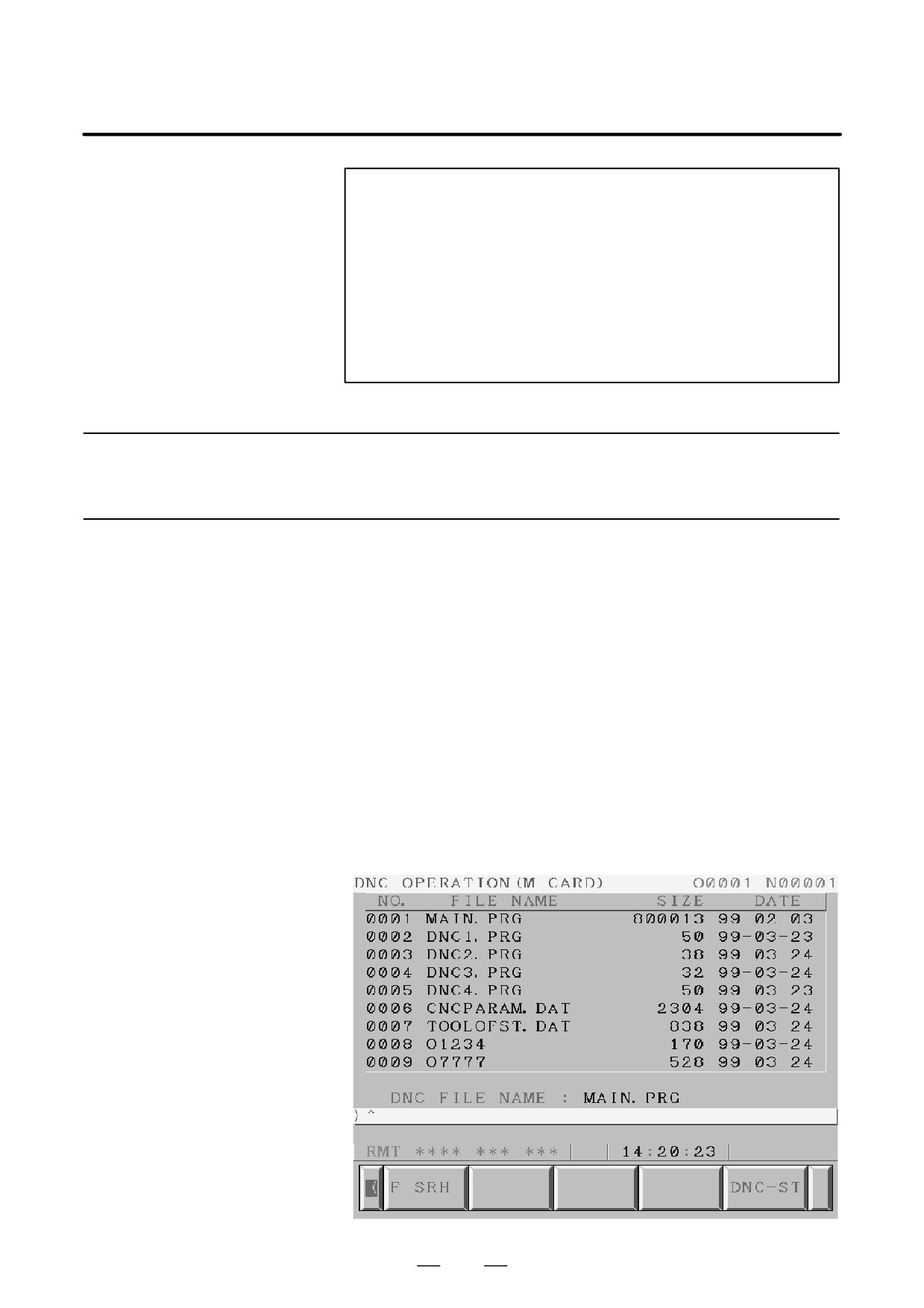
Procedure
Please set the parameter of No.20 to 4 in the setting screen in advance.
(1) Change to RMT mode.
(2) Push [PROGRAM] function key.
(3) Push [ > ] soft key (continuance menu).
(4) When [DNC-CD] soft key is pushed, the following screen is
displayed.
(5) The screen can be scrolled by page key. An arbitrary file number is
input, and [F SRH] soft key is pushed. Then the arbitrary file name
is displayed at the top of DNC operation (memory card) screen.
(6) When the file number that is executed is input and the [DNC-ST] soft
key is pushed, the file name that is selected is set to DNC FILE.
(7) When the cycle start is done, the program that is selected is executed.
546
B-63524EN/01
OPERATION
4. AUTOMATIC OPERATION
4.10.2.2
When the following block in a program in CNC memory is executed, a
subprogram file in memory card is called.
Subprogram call (M198)
Format
1. Normal format
M198 Pffff ∆∆∆∆ ;
File number for a file in
the memory card
Number of repetition
Memory card call instruction
2. FS15 tape format
M198 Pffff L∆∆∆∆ ;
File number of repetition
File number for a file in the
memory card
Memory card call instruction
Explanation
When the custom macro option is provided, both format 1 and 2 can be
used. A different M code can be used for a subprogram call depending
on the setting of parameter No. 6030. In this case, M198 is executed as
a normal M code. The file number is specified at address P. If the SBP
(bit 2) of parameter No. 3404 is set to 1, a program number can be
specified. When a file number is specified at address P, Fxxxx is indicated
instead of Oxxxx.
NOTE
Please set the parameter of No. 20 to 4 in the setting screen
in advance.
547
4. AUTOMATIC OPERATION
OPERATION
B-63524EN/01
4.10.3
(1) The memory card can not be accessed, such as display of memory card
list and so on, during the DNC operation with memory card.
Limitation and Notes
(2) It is possible to execute the DNC operation with memory card on multi
path system. However, it is not possible to call programs from the
plural paths at the same time.
(3) The selection of DNC operation file that is set at DNC OPERATION
screen is cleared by the power supply turn off and on. After the power
supply is turned on again, it is necessary to select the DNC operation
file again.
(4) Please do not pull out and insert memory card during the DNC
operation with memory card.
(5) It is not possible to call a program in the memory card from the DNC
operation program.
(6) In case of using this function, the PMCIA card attachment written at
section 6 must be used to prevent a poor connection of the memory
card from occurring by vibration of the machine.
(7) In case of the stand-alone type i series that the display unit is a Display
link unit, this function can not be used.
(8) The memory card interface on the stand-alone type controller is not
available. Please use the memory card interface on the display unit.
4.10.4
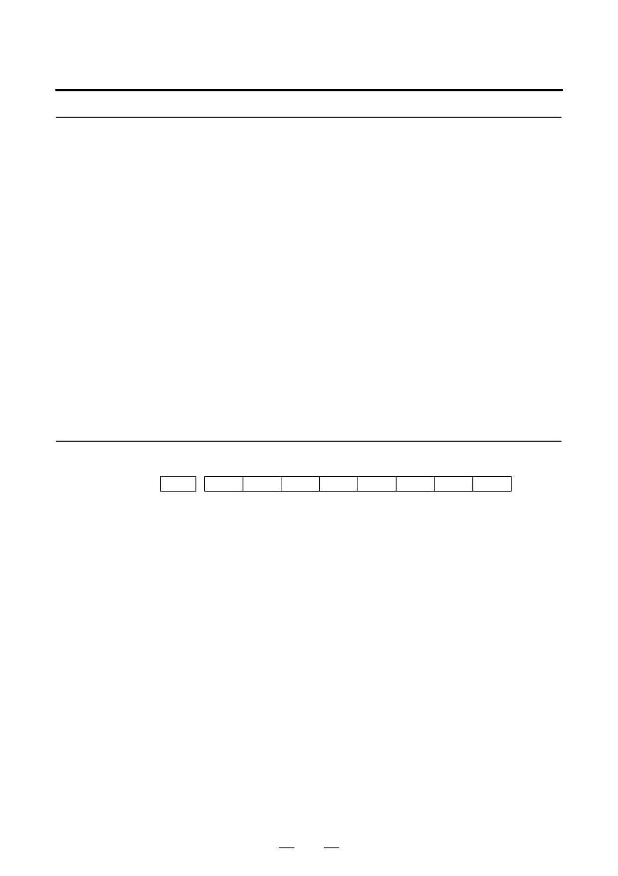
#7
#6
#5
#4
#3
#2
#1
#0
Parameter
0138
DNM
[Data type] Bit
#7 (DNM) The DNC operation with memory card function is
0 : disable.
1 : enable.
548