FANUC Series Series 16i-TB, Series 18i-TB, Series 160i-TB, Series 180i-TB. OPERATOR’S MANUAL - page 18
B-63524EN/01
OPERATION
3. MANUAL OPERATION
Explanations
D Manual per revolution
To enable manual per revolution feed, set bit 4 (JRV) of parameter No.
feed
1402 to 1.
During manual per revolution feed, the tool is jogged at the following
feedrate:
Feed distance per rotation of the spindle (mm/rev) (specified with
parameter No. 1423) x JOG feedrate override x actual spindle speed
(rev/min).
Restrictions
D Acceleration/decelera-
Feedrate, time constant and method of automatic acceleration/
tion for rapid traverse
deceleration for manual rapid traverse are the same as G00 in programmed
command.
D Change of modes
Changing the mode to the JOG feed mode while pressing a feed axis and
direction selection switch does not enable JOG feed. To enable JOG feed,
enter the JOG feed mode first, then press a feed axis and direction
selection switch.
D Rapid traverse prior to
If reference position return is not performed after power-on, pushing
reference position return
RAPID TRAVERSE button does not actuate the rapid traverse but the
remains at the manual continuous feedrate. This function can be disabled
by setting parameter RPD (No.1401#01).
489
3.MANUAL OPERATION
OPERATION
B-63524EN/01
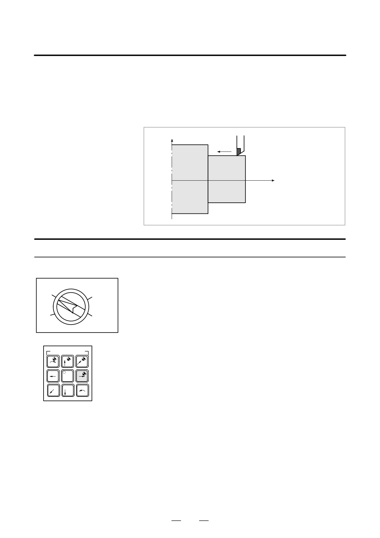
In the incremental (INC) mode, pressing a feed axis and direction
3.3
selection switch on the machine operator’s panel moves the tool one step
INCREMENTAL FEED
along the selected axis in the selected direction. The minimum distance
the tool is moved is the least input increment. Each step can be 10, 100,
or 1000 times the least input increment.
This mode is effective when a manual pulse generator is not
connected.
X
Tool
Each time a switch is
pressed, the tool moves
one step in the direction
specified by the switch.
Workpiece
Z
Procedure for Incremental Feed
1
Press the INC switch, one of the mode selection switches.
2
Select the distance to be moved for each step with the magnification
X10
X100
dial.
3
Press the feed axis and direction selection switch corresponding to the
axis and direction the tool is to be moved. Each time a switch is
X1
X1000
pressed, the tool moves one step. The feedrate is the same as the jog
feedrate.
4
Pressing the rapid traverse switch while pressing a feed axis and
AXIS DIRECTION
direction selection switch moves the tool at the rapid traverse rate.
Rapid traverse override by the rapid traverse override switch is
+C
+X
+Y
effective during rapid traverse.
–Z
rapid
+Z
The above is an example. Refer to the appropriate manual provided
-y
-X
-C
by the machine tool builder for the actual operations.
Explanation
D Travel distance
The distance the tool travels along the X-axis can be specified with a
specified with a
diameter.
diameter
490
B-63524EN/01
OPERATION
3. MANUAL OPERATION
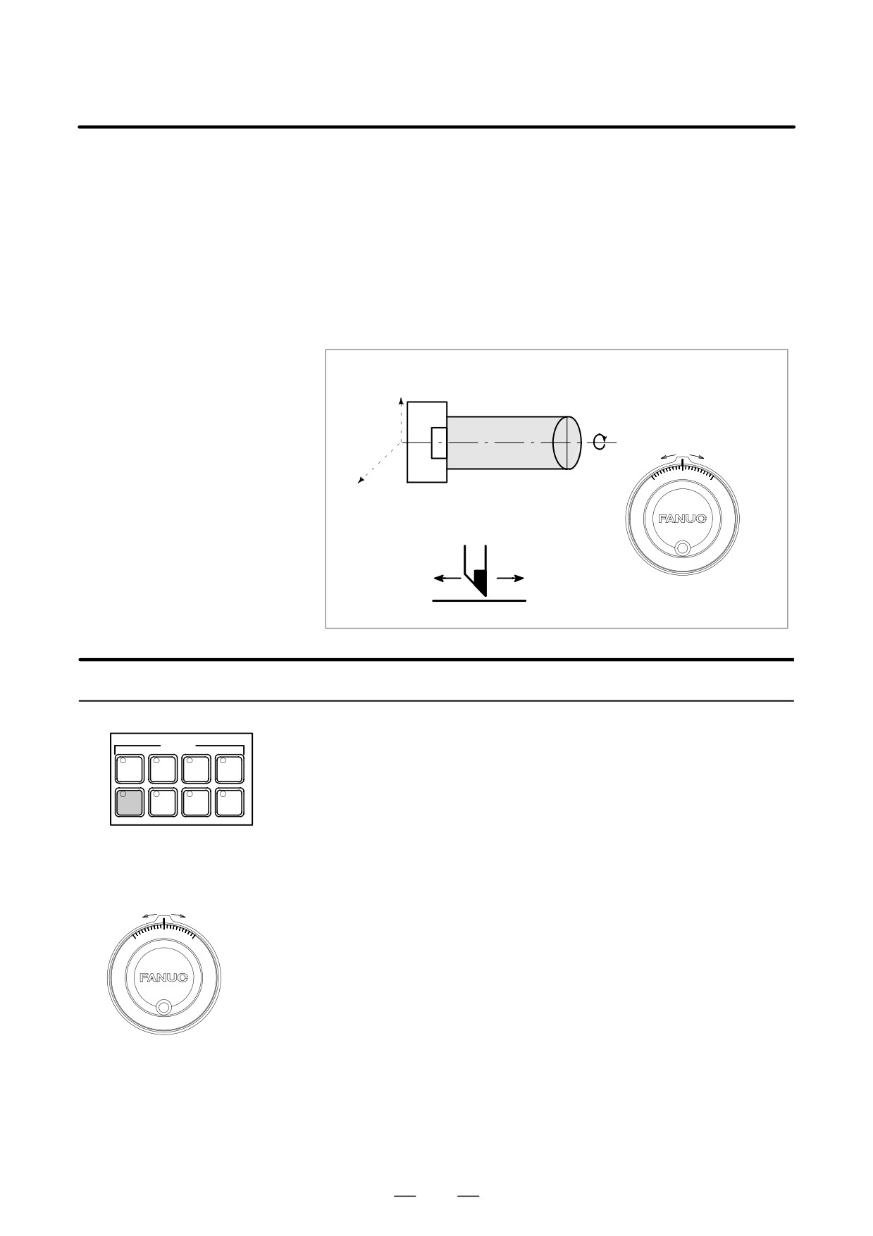
In the handle mode, the tool can be minutely moved by rotating the
3.4
manual pulse generator on the machine operator’s panel. Select the axis
MANUAL HANDLE
along which the tool is to be moved with the handle feed axis selection
FEED
switches.
The minimum distance the tool is moved when the manual pulse
generator is rotated by one graduation is equal to the least input increment.
Or the distance the tool is moved when the manual pulse generator is
rotated by one graduation can be magnified by 10 times or by one of the
two magnifications specified by parameters (No. 7113 and 7114).
X
Z
Y
Manual pulse generator
Procedure for Manual Handle Feed
1
Press the HANDLE switch, one of the mode selection switches.
MODE
EDIT
MEMORY
REMOTE
MDI
2
Select the axis along which the tool is to be moved by pressing a
handle feed axis selection switch.
HANDLE
JOG
ZERO
TEACH
RETURN
3
Select the magnification for the distance the tool is to be moved by
pressing a handle feed magnification switch. The minimum distance
the tool is moved when the manual pulse generator is rotated by one
graduation is equal to the least input increment.
4
Move the tool along the selected axis by rotating the handle. Rotating
the handle 360 degrees moves the tool the distance equivalent to 100
graduations.
The above is an example. Refer to the appropriate manual provided by
the machine tool builder for the actual operations.
Manual pulse generator
491
3.MANUAL OPERATION
OPERATION
B-63524EN/01
Explanation
D Availability of manual
Parameter JHD (bit 0 of No. 7100) enables or disables the manual pulse
pulse generator in Jog
generator in the JOG mode.
mode (JHD)
When the parameter JHD( bit 0 of No. 7100) is set 1,both manual handle
feed and incremental feed are enabled.
D Availability of manual
Parameter THD (bit 1 of No. 7100) enables or disables the manual pulse
pulse generator in
generator in the TEACH IN JOG mode.
TEACH IN JOG mode
(THD)
D A command to the MPG
Parameter HPF (bit 4 of No. 7100) or (No. 7117) specifies as follows:
exceeding rapid traverse
D Parameter HPF (bit 4 of No. 7100)
rate (HPF)
Set value 0 : The feedrate is clamped at the rapid traverse rate and
generated pulses exceeding the rapid traverse rate are
ignored. (The distance the tool is moved may not match
the graduations on the manual pulse generator.)
Set value 1 : The feedrate is clamped at the rapid traverse rate and
generated pulses exceeding the rapid traverse rate are not
ignored but accumulated in the CNC.
(No longer rotating the handle does not immediately
stop the tool. The tool is moved by the pulses
accumulated in the CNC before it stops.)
D Parameter HPF (No. 7177) (It is available when parameter HPF is 0.)
Set value 0 : The feedrate is clamped at the rapid traverse rate and
generated pulses exceeding the rapid traverse rate are
ignored. (The distance the tool is moved may not match
the graduations on the manual pulse generator.)
Other than 0 : The feedrate is clamped at the rapid traverse rate and
generated pulses exceeding the rapid traverse rate are not
ignored but accumulated in the CNC until the limit
specified in parameter No. 7117 is reached.
(No longer rotating the handle does not immediately
stop the tool. The tool is moved by the pulses
accumulated in the CNC before it stops.)
D Movement direction of
Parameter HNGx (bit 0 of No. 7102) switches the direction of MPG in
an axis to the rotation of
which the tool moves along an axis, corresponding to the direction in
MPG (HNGx)
which the handle of the manual pulse generator is rotated.
Restrictions
D Number of MPGs
Up to three manual pulse generators can be connected, one for each axis.
The three manual pulse generators can be simultaneously operated.
492
B-63524EN/01
OPERATION
3. MANUAL OPERATION
WARNING
Rotating the handle quickly with a large magnification such
as x100 moves the tool too fast. The feedrate is clamped
at the rapid traverse feedrate.
NOTE
Rotate the manual pulse generator at a rate of five rotations
per second or lower. If the manual pulse generator is
rotated at a rate higher than five rotations per second, the
tool may not stop immediately after the handle is no longer
rotated or the distance the tool moves may not match the
graduations on the manual pulse generator.
493
3.MANUAL OPERATION
OPERATION
B-63524EN/01
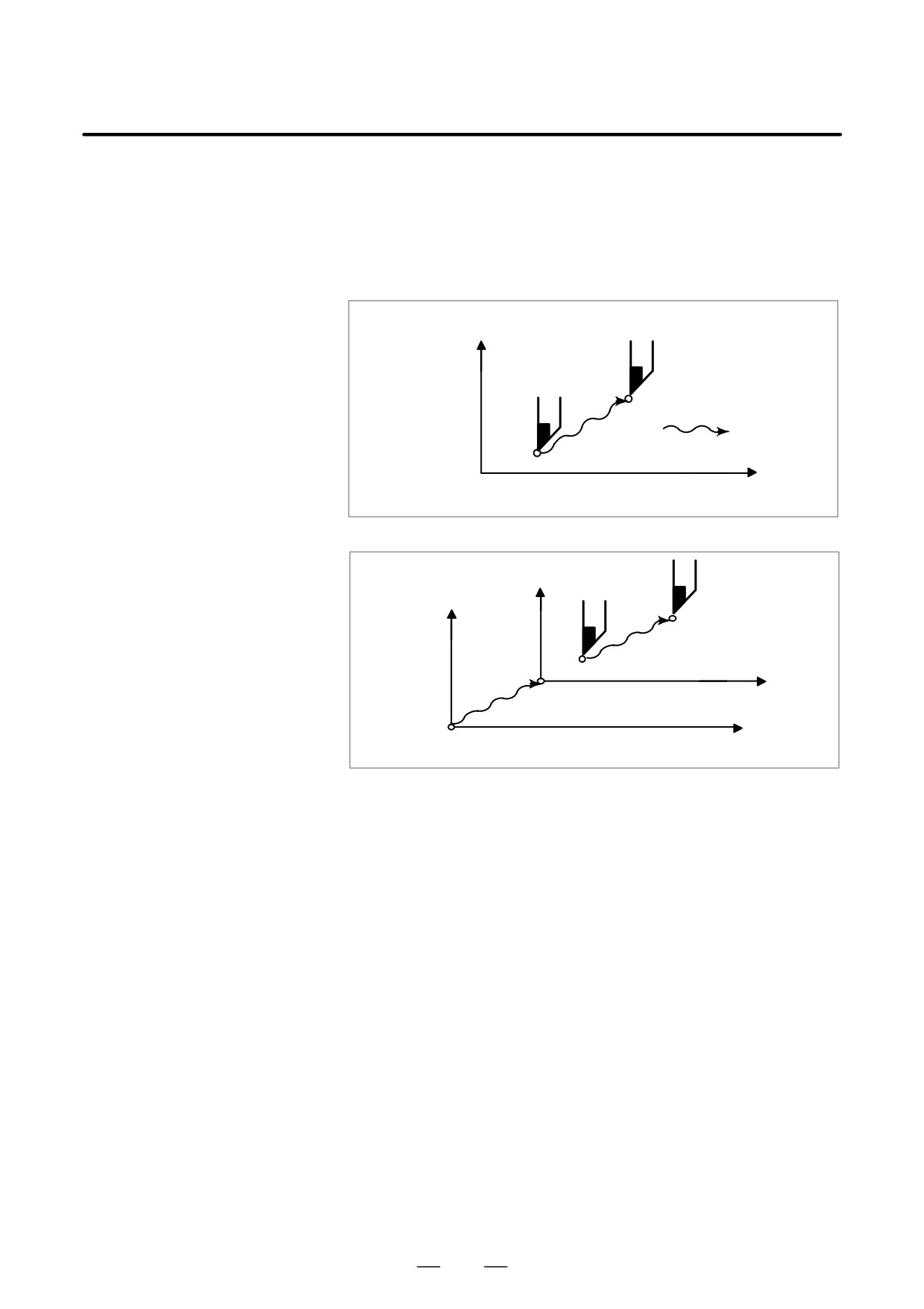
Whether the distance the tool is moved by manual operation is added to
3.5
the coordinates can be selected by turning the manual absolute switch on
MANUAL ABSOLUTE
or off on the machine operator’s panel. When the switch is turned on, the
ON AND OFF
distance the tool is moved by manual operation is added to the
coordinates. When the switch is turned off, the distance the tool is moved
by manual operation is not added to the coordinates.
X axis
P2
Manual operation
P1
O
Z axis
The coordinates values change by the amount of manual operation.
Fig. 3.5 (a) Coordinates with the switch ON
X2
X1
P2
O2
P1
Z2
Z1
O1
The coordinates do not change.
Fig. 3.5 (b) Coordinates with the switch OFF
494
B-63524EN/01
OPERATION
3. MANUAL OPERATION
Explanation
The following describes the relation between manual operation and
coordinates when the manual absolute switch is turned on or off, using a
program example.
G01G90 X100.0Z100.0F010
;
(1)
X200.0Z150.0
;
(2)
X300.0Z200.0
;
(3)
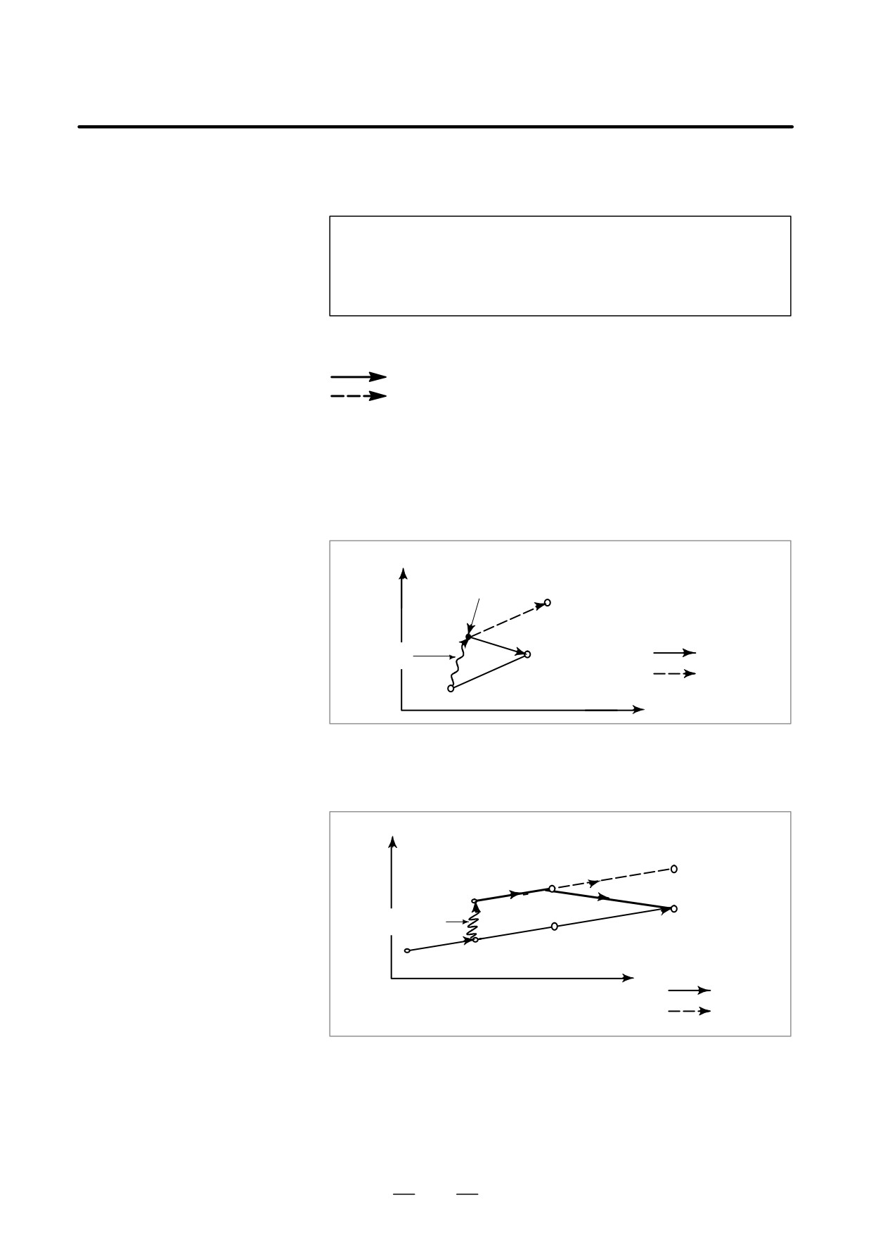
The subsequent figures use the following notation:
Movement of the tool when the switch is on
Movement of the tool when the switch is off
The coordinates after manual operation include the distance the tool is
moved by the manual operation. When the switch is off, therefore,
subtract the distance the tool is moved by the manual operation.
D Manual operation after
Coordinates when block (2) has been executed after manual operation
the end of block
(X-axis +20.0, Z-axis +100.0) at the end of movement of block (1).
X
(220.0 , 250.0)
(120.0 , 200.0)
Manual
Switch ON
(200.0 , 150.0)
operation
Switch OFF
(100.0 , 100.0)
Z
D Manual operation after a
Coordinates when the feed hold button is pressed while block (2) is being
feed hold
executed, manual operation (X-axis + 75.0) is performed, and the cycle
start button is pressed and released
X
(375.0 , 200.0)
(275.0 , 150.0)
(225.0 , 125.0)
Manual
operation
(200.0 , 150.0)
(300.0 , 200.0)
(150.0 , 125.0)
Z
Switch ON
Switch OFF
495
3.MANUAL OPERATION
OPERATION
B-63524EN/01
D When reset after a
Coordinates when the feed hold button is pressed while block (2) is being
manual operation
executed, manual operation (Y-axis +75.0) is performed, the control unit
following a feed hold
is reset with the RESET button, and block (2) is read again
X
(375.0 , 200.0)
(275.0,150.0)
(225.0 , 125.0)
Manual
(300.0 , 200.0)
operation
(200.0,150.0)
(100.0 , 100.0)
(150.0 , 125.0)
Switch ON
Z
Switch OFF
D When a movement
When there is only one axis in the following command, only the
command in the next
commanded axis returns.
block is only one axis
N1G01X100.0Z100.0F500;
X
(150.0 , 200.0)
N2Z200.0;
N3X150.0;
Manual
operation
N3
Switch ON
N2
(100.0 , 200.0)
Switch OFF
N1
(100.0 , 100.0)
Z
D When the next move
When the following commands are incremental commands, operation is
block is an incremental
the same as when the switch is OFF.
D Manual operation during
tool nose radius
compensation
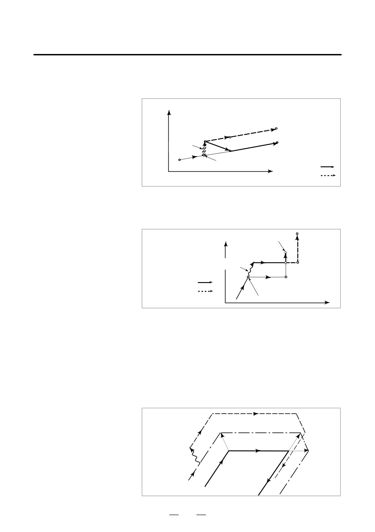
When the switch is OFF
After manual operation is performed with the switch OFF during tool
nose radius compensation, automatic operation is restarted then the tool
moves parallel to the movement that would have been performed if
manual movement had not been performed. The amount of separation
equals to the amount that was performed manually.
Cutter path after
manual operation
Manual
operation
Tool nose radius path
Programmed path
496
B-63524EN/01
OPERATION
3. MANUAL OPERATION
When the switch is ON during tool nose radius compensation
Operation of the machine upon return to automatic operation after manual
intervention with the switch is ON during execution with an absolute
command program in the tool nose radius compensation mode will be
described. The vector created from the remaining part of the current block
and the beginning of the next block is shifted in parallel. A new vector is
created based on the next block, the block following the next block and
the amount of manual movement. This also applies when manual
operation is performed during cornering.
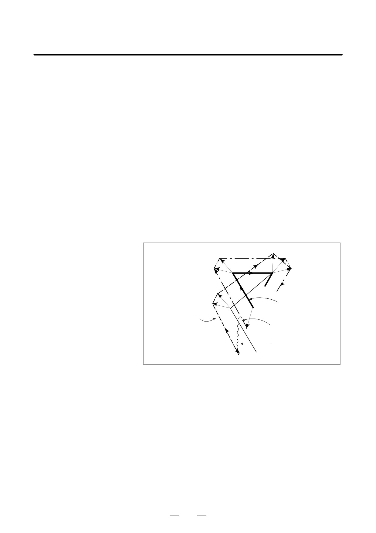
Manual operation performed in other than cornering
Assume that the feed hold was applied at point PH while moving from PA
to PB of programmed path PA, PB, and PC and that the tool was manually
moved to PH’. The block end point PB moves to the point PB’ by the
amount of manual movement, and vectors VB1 and VB2 at PB also move
to VB1’ and VB2’. Vectors VC1 and VC2 between the next two blocks PB
- PC and PC - PD are discarded and new vectors VC1’ and VC2’ (VC2’ =
VC2 in this example) are produced from the relation between PB’ - PC and
PC - PD. However, since VB2’ is not a newly calculated vector, correct
offset is not performed at block PB’ - PC. Offset is correctly performed
after PC.
VC1’
VB2
VC1
VB1
PB
PC
VC2
VB2’
PD
Programmed path
VB1’
(absolute com-
PA
P’B
mand)
PH
Tool nose radius
Tool nose radius
path after
path before
manual operation
manual operation
Manual operation
PH’
497
3.MANUAL OPERATION
OPERATION
B-63524EN/01
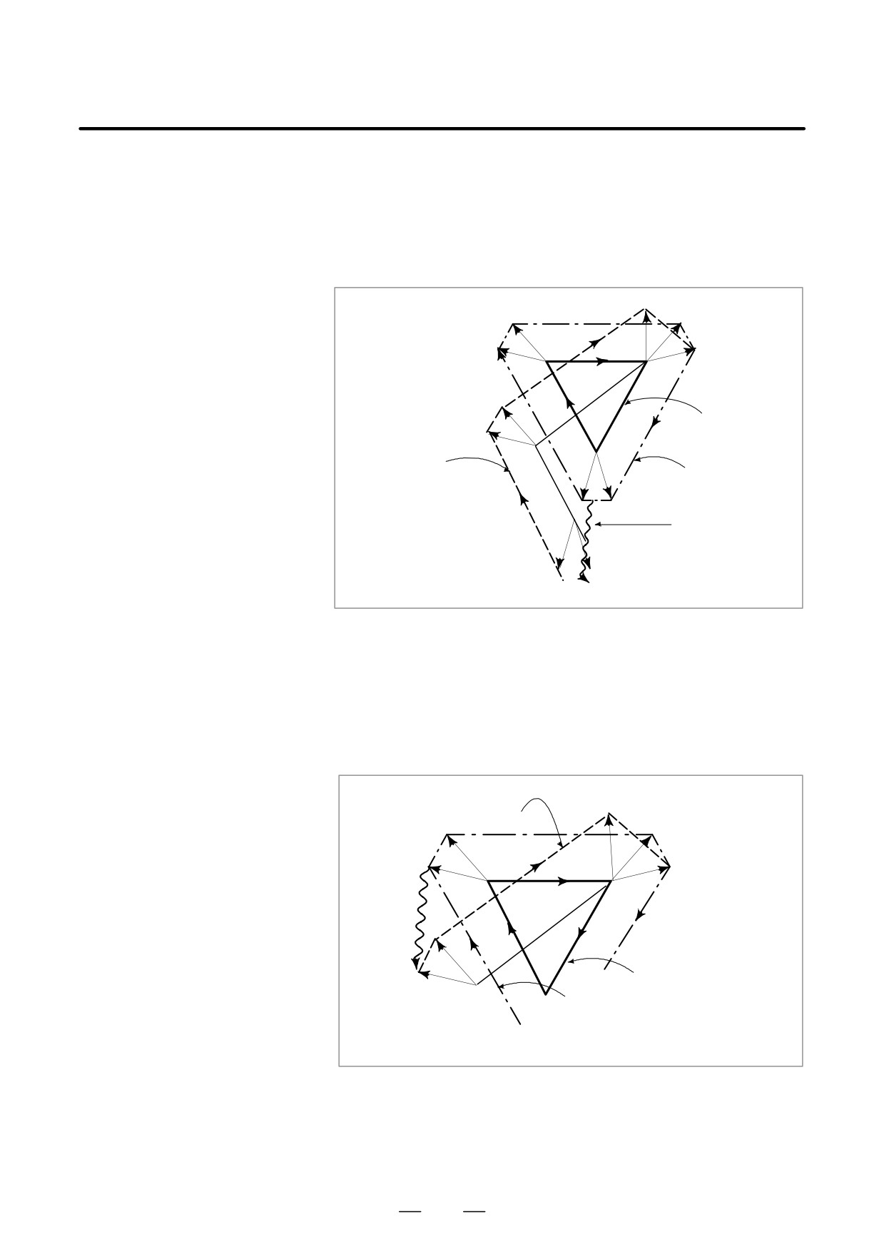
Manual operation during cornering
This is an example when manual operation is performed during cornering.
VA2’, VB1’, and VB2’ are vectors moved in parallel with VA2, VB1 and VB2
by the amount of manual movement. The new vectors are calculated
from VC1 and VC2. Then correct tool nose radius compensation is
performed for the blocks following Pc.
VC1’
VB2
VC1
VB1
PB
PC
VC2
VB2’
VB1’
Programmed path
(absolute command)
Tool nose radius
PA
path after
Tool nose radius
manual operation
path before
manual operation
VA2
VA1
PH
PA’
Manual operation
VA1’
VA2’
PH’
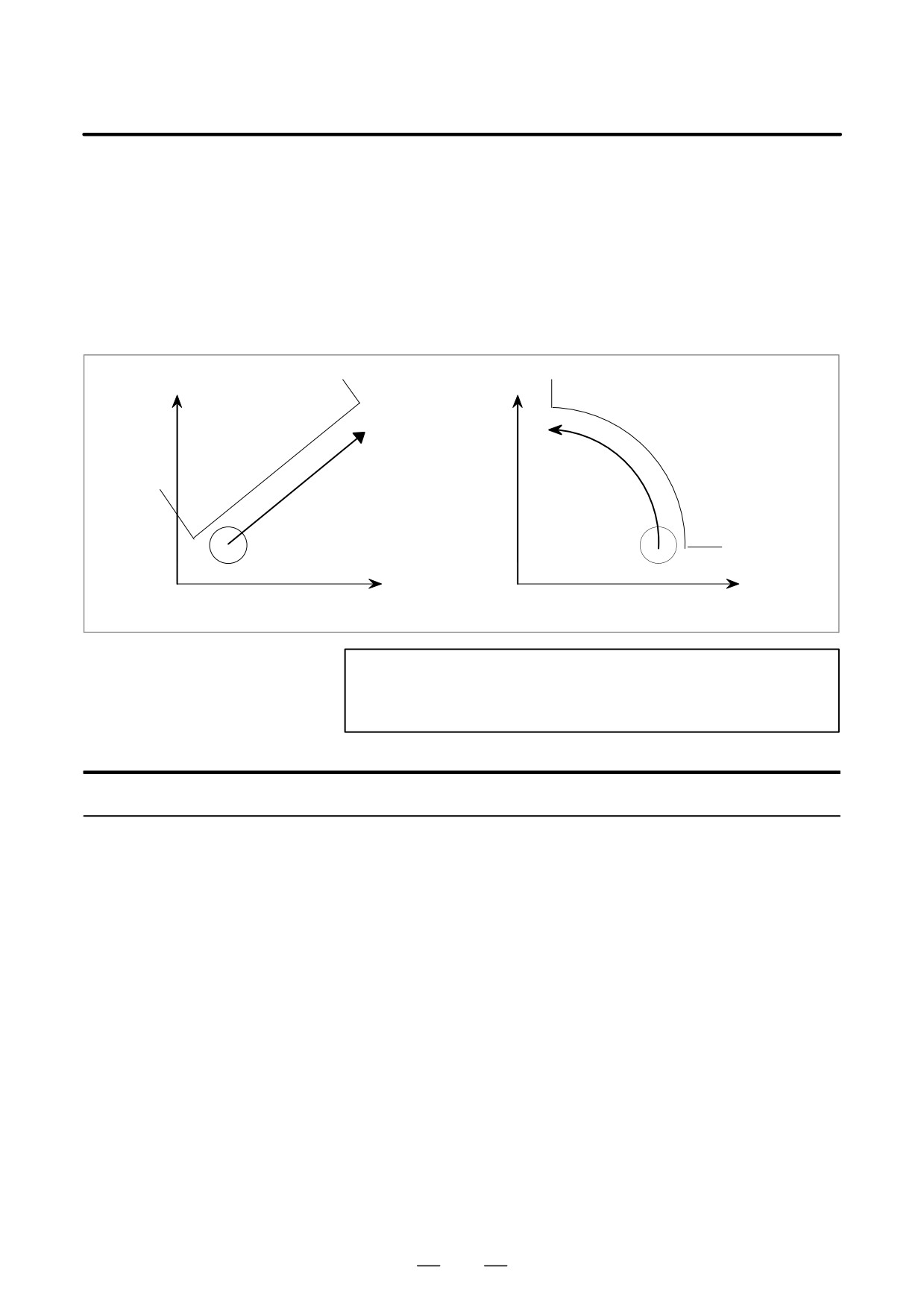
Manual operation after single block stop
Manual operation was performed when execution of a block was
terminated by single block stop.
Vectors VB1 and VB2 are shifted by the amount of manual operation.
Sub-sequent processing is the same as case a described above. An MDI
operation can also be interveneted as well as manual operation. The
movement is the same as that by manual operation.
Tool nose radius path after
VC1’
manual operation
VB2
VC1
VB1
PB
PC
VC2
Manual
operation
VB2’
Programmed path
VB1’
PB’
(absolute command)
PA Tool nose radius
path before
manual operation
498
B-63524EN/01
OPERATION
3. MANUAL OPERATION
In manual handle feed or jog feed, the following types of feed operations
3.6
are enabled in addition to the conventional feed operation along a
MANUAL
specified single axis (X-axis, Y-axis, Z-axis, and so forth) based on
LINEAR/CIRCULAR
simultaneous 1-axis control:
INTERPOLATION
D Feed along a tilted straight line in the XY plane (linear feed) based on
simultaneous 2-axis control
D Feed along a circle in the XY plane (circular feed) based on
simultaneous 2-axis control
Y
Y
Workpiece
Workpiece
Tool
Tool
X
X
<<Linear feed>>
<<Circular feed>>
NOTE
The X-axis and Y-axis must be the first controlled axis and
second controlled axis, respectively.
Procedure for Manual Linear/Circular Interpolation
Procedure
1
To perform manual handle feed, select manual handle feed mode. To
perform jog feed, select jog feed mode.
2
To perform manual handle feed, select a feed axis (for simultaneous
1-axis feed along the X-axis, Y-axis, or Z-axis, or for simultaneous
linear or circular 2-axis feed along a specified straight line or circle in
the XY plane) subject to manual handle feed operation. Use the
handle feed axis select switch for this selection.
To perform jog feed, select a feed axis and direction with the feed axis
direction select switch. While a feed axis and its direction are
specified, the tool moves in the specified axis direction or along a
straight line or circle at the jog feedrate specified in parameter No.
1423.
3
For manual handle feed
The tool is moved along a specified axis by turning the respective
manual handle. The feedrate depends on the speed at which the
manual handle is turned. A distance to be traveled by the tool when
the manual handle is turned by one pulse can be selected using the
manual handle feed travel distance magnification switch.
499
3.MANUAL OPERATION
OPERATION
B-63524EN/01
For jog feed
The feedrate can be overridden using the manual feedrate override
dial.
The procedure above is just an example. For actual operations, refer
to the relevant manual provided by the machine tool builder.
Explanations
D Definition of a straight
For feed along an axis, no straight line/circle definition is required. For
line/circle
linear feed or circular feed, a straight line or circle must be defined
beforehand. (For circular feed, for example, data such as a radius and the
center of a circle must be set.) For details, refer to the relevant manual
provided by the machine tool builder.
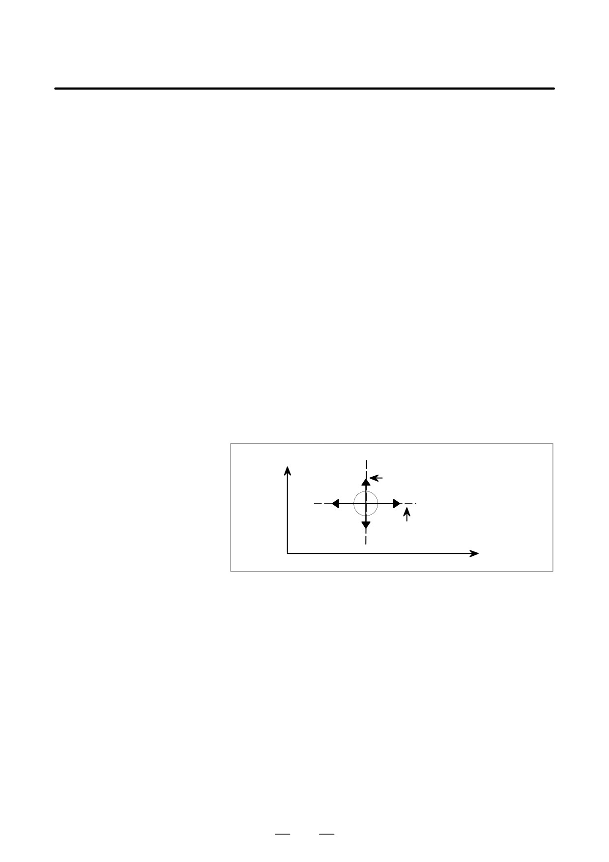
D Manual handle feed
In manual handle feed, the tool can be moved along a specified axis
(X-axis, Y-axis, Z-axis, ..., or the 8th axis), or can be moved along a
tilted straight line (linear feed) or a circle (circular feed).
(1) Feed along a specified axis (simultaneous 1-axis control)
By turning a manual handle, the tool can be moved along the desired
axis (such as X-axis, Y-axis, and Z-axis) on a simultaneous 1-axis
control basis. (This mode of feed is the conventional type of manual
handle feed.)
Y
Path of travel using the Y-axis handle
Path of travel using the X-axis handle
X
Feed along a specified axis
500
B-63524EN/01
OPERATION
3. MANUAL OPERATION
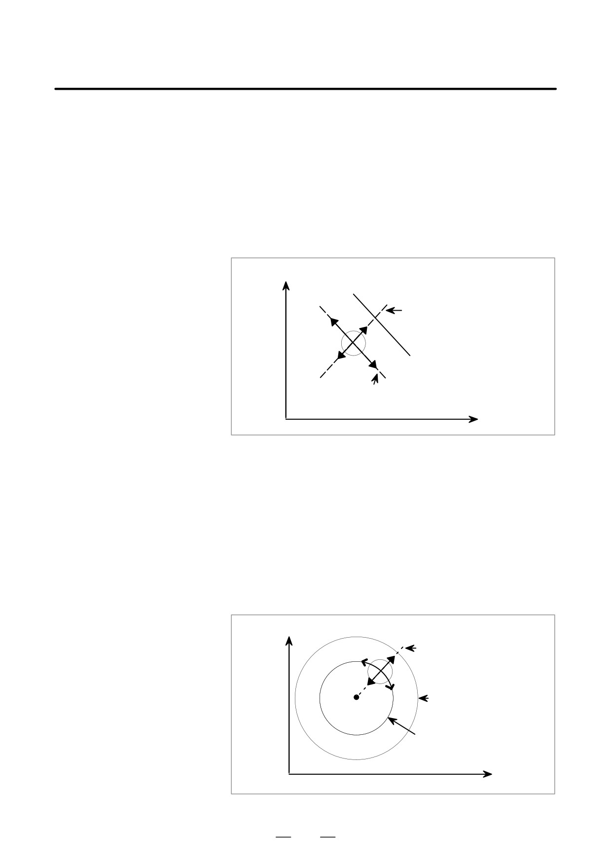
(2) Linear feed (simultaneous 2-axis control)
By turning a manual handle, the tool can be moved along the straight
line parallel to a specified straight line on a simultaneous 2-axis
control basis. This manual handle is referred to as the guidance handle.
Moreover, by turning another manual handle, the tool can be moved
at right angles to a specified straight line on a simultaneous 2-axis
control basis. This manual handle is referred to as the approach
handle. When the guidance handle or approach handle is turned
clockwise or counterclockwise, the tool travels forward or backward
along the respective path.
Y
Path of travel using
the approach handle
Tool
Specified straight line
Path of travel using the
guidance handle
X
Linear feed
(3) Circular feed (simultaneous 2-axis control)
By turning a manual handle, the tool can be moved from the current
position along the concentric circle that has the same center as a
specified circle on a simultaneous 2-axis control basis. This manual
handle is referred to as the guidance handle. Moreover, by turning
another manual handle, the tool can be moved along the normal to a
specified circle on a simultaneous 2-axis control basis. This manual
handle is referred to as the approach handle. When the guidance
handle or approach handle is turned clockwise or counterclockwise,
the tool travels forward or backward along the respective path.
Y
Path of travel using the
approach handle
Specified circle
Path of travel using the
guidance handle
X
Circular feed
501
3.MANUAL OPERATION
OPERATION
B-63524EN/01
D Feedrate for manual
Feedrate
handle feed
The feedrate depends on the speed at which a manual handle is turned.
A distance to be traveled by the tool (along a tangent in the case of linear
or circular feed) when a manual handle is turned by one pulse can be
selected using the manual handle feed travel distance magnification
switch.
The FS16/18 has three manual pulse generator interfaces to allow up to
D Manual handle selection
three manual handles to be connected. For information about how to use
the manual handles connected to the interfaces (whether to use each
manual handle as a handle for feed along an axis, as a guidance handle,
or as an approach handle), refer to the relevant manual provided by the
machine tool builder.
D Direction of movement
The user can specify the direction of the tool moved along a straight line
using manual handles
or circle (for example, whether to make a clockwise or counterclockwise
movement along a circle) when the guidance handle or approach handle
is turned clockwise or counterclockwise. For details, refer to the relevant
manual provided by the machine tool builder.
D Jog feed (JOG)
In jog feed, the tool can be moved along a specified axis (X-axis, Z-axis,
..., or the 8th axis), or can be moved along a tilted straight line (linear feed)
or a circle (circular feed).
(1) Feed along a specified axis (simultaneous 1-axis control)
While a feed axis and its direction are specified with the feed axis
direction select switch, the tool moves in the specified axis direction
at the feedrate specified in parameter No. 1423. The feedrate can be
overridden using the manual feedrate override dial.
(2) Linear feed (simultaneous 2-axis control)
By defining a straight line beforehand, the tool can be moved as
follows:
D While a feed axis and its direction are selected using the feed axis
direction select switch, the tool moves along a straight line parallel
to the specified straight line on a simultaneous 2-axis control basis.
D While a feed axis and its direction are selected using the feed axis
direction select switch, the tool moves at right angles to the
specified straight line on a simultaneous 2-axis control basis.
The feedrate in the tangential direction is specified in parameter No.
1410. The feedrate can be overridden using the manual feedrate
override dial.
(3) Circular feed (simultaneous 2-axis control)
By defining a circle beforehand, the tool can be moved as follows:
D While a feed axis and its direction are selected using the feed axis
direction select switch, the tool moves from the current position
along the concentric circle that has the same center as the specified
circle.
D While a feed axis and its direction are selected using the feed axis
direction select switch, the tool moves along the normal to the
specified circle.
The feedrate in the tangential direction is specified in parameter No.
1410. The feedrate can be overridden using the manual feedrate
override dial.
502
B-63524EN/01
OPERATION
3. MANUAL OPERATION
D Manual handle feed in
Even in JOG mode, manual handle feed can be enabled using bit 0 (JHD)
JOG mode
of parameter No. 7100. In this case, however, manual handle feed is
enabled only when the tool is not moved along any axis by jog feed.
Limitations
D Mirror image
Never use the mirror image function when performing manual operation.
(Perform manual operation when the mirror image switch is off, and
mirror image setting is off.)
503
3.MANUAL OPERATION
OPERATION
B-63524EN/01
The manual numeric command function allows data programmed
3.7
through the MDI to be executed in jog mode. Whenever the system is
MANUAL NUMERIC
ready for jog feed, a manual numeric command can be executed. The
COMMAND
following eight functions are supported:
(1) Positioning (G00)
(2) Linear interpolation (G01)
(3) Automatic reference position return (G28)
(4)2nd/3rd/4th reference position return (G30)
(5) M codes (miscellaneous functions)
(6) S codes (spindle functions)
(7) B codes (second auxiliary functions)
By setting the following parameters, the commands for axial motion and
the M, S, T, and B functions can be disabled:
(1) Positioning (G00)
(2) Linear interpolation (G01):
Bit 0 (JAXx) of
(3) Automatic reference position
return (G28):
parameter No. 7010
(4)2nd/3rd/4th reference position
return (G30):
(5) M codes (miscellaneous functions):
Bit 0 (JMF) of parameter No. 7002
(6) S codes (spindle functions):
Bit 1 (JSF) of parameter No. 7002
(7) B codes (second auxiliary functions):
Bit 3 (JBF) of parameter No. 7002
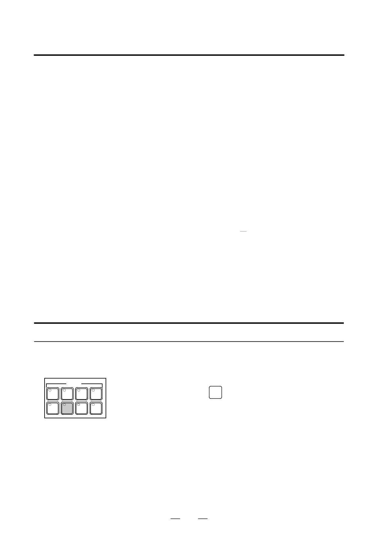
Procedure
Manual numeric command
Procedure
1
Press the jog switch (one of the mode selection switches).
MODE
EDIT
MEMORY
REMOTE
MDI
2
Press function key
PROG
HANDLE
JOG
ZERO
TEACH
RETURN
3
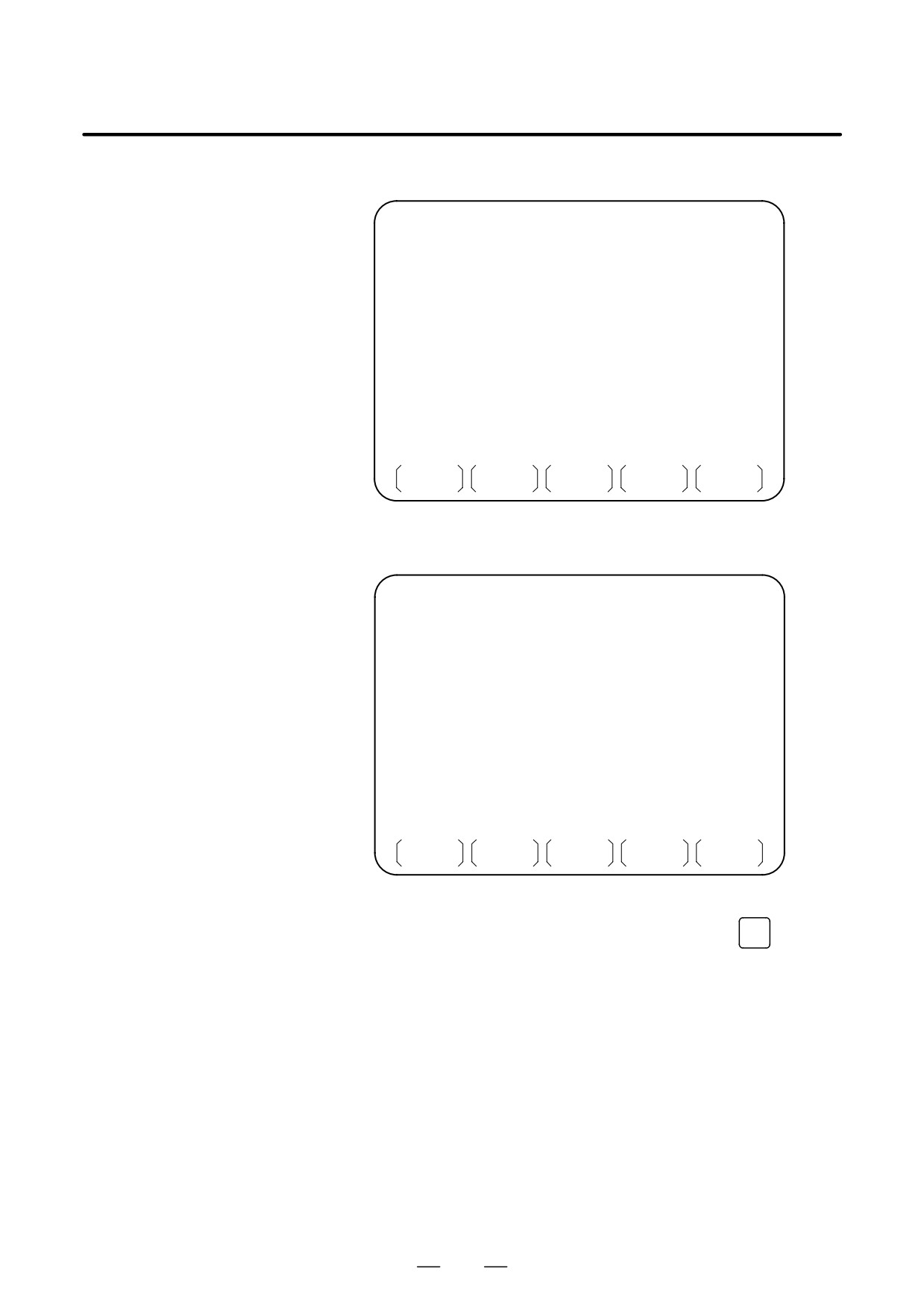
Press soft key [JOG] on the screen. The following manual numeric
command screen is displayed.
504
B-63524EN/01
OPERATION
3. MANUAL OPERATION
Example 1: When the maximum number of controlled axes is six
PROGRAM (JOG)
O0010 N00020
G00 P
(ABSOLUTE)
(DISTANCE TO GO)
X
X
0.000
X
0.000
Y
Y
0.000
Y
0.000
Z
Z
0.000
Z
0.000
U
U
0.000
U
0.000
V
V
0.000
V
0.000
W
W
0.000
W
0.000
M
S
T
B
>_
JOG
* * * *
* * *
* * *
00 : 00 : 00
PRGRM
JOG
CURRNT
NEXT
(OPRT)
Example 2: When the maximum number of controlled axes is 7 or 8
PROGRAM (JOG)
O0010 N00020
G00 P
(ABSOLUTE)
(DISTANCE TO GO)
X
X
0.000
X
0.000
Y
Y
0.000
Y
0.000
Z
Z
0.000
Z
0.000
U
U
0.000
U
0.000
V
V
0.000
V
0.000
W
W
0.000
W
0.000
A
A
0.000
A
0.000
C
C
0.000
C
0.000
M T
S
B
>_
JOG
* * * *
* * *
* * *
00 : 00 : 00
PRGRM
JOG
CURRNT
NEXT
(OPRT)
4
Enter the required commands by using address keys and numeric keys
on the MDI panel, then press soft key [INPUT] or the
INPUT
key to set
the entered data.
505
3.MANUAL OPERATION
OPERATION
B-63524EN/01
PROGRAM (JOG)
O0010 N00020
G00 P
(ABSOLUTE)
(DISTANCE TO GO)
X
10.000
X
0.000
X
0.000
Y
Y
0.000
Y
0.000
Z
Z
0.000
Z
0.000
U
U
0.000
U
0.000
V
V
0.000
V
0.000
W
W
0.000
W
0.000
M
S
T
B
>Z120.5_
JOG
* * * *
* * *
* * *
00 : 00 : 00
CLEAR
INPUT
The following data can be set:
1. G00: Positioning
2. G01: Linear interpolation
3. G28: Automatic reference position return
4. G30: 2nd/3rd/4th reference position return
5. M codes: Miscellaneous functions
6. S codes: Spindle functions
7. B codes: Second auxiliary functions
The set data is maintained even when the screen or mode is changed.
NOTE
When an alarm state exists, data cannot be set.
5
Press the cycle start switch on the machine operator’s panel to start
command execution. The status is indicated as “MSTR.” (When the
9″ screen is being used, the actual feedrate “ACT.F” and spindle
speed “SACT” appear on the key input line.) The automatic operation
signal, STL, can be turned on by setting bit 2 (JST) of parameter No.
7001.
ACT.F
1000 SACT
0
JOG MASTR***MTN
00:00:00
NOTE
If the cycle start switch is pressed while an alarm state
exists, a “START IMPOSSIBLE” warning is generated, and
the entered data cannot be executed.
6
Upon the completion of execution, the “MSTR” status indication is
cleared from the screen, and automatic operation signal STL is turned
off. The set data is cleared entirely. G codes are set to G00 or G01
according to the setting of bit 0 (G01) of parameter No. 3402.
506
B-63524EN/01
OPERATION
3. MANUAL OPERATION
Explanations
D Positioning
An amount of travel is given as a numeric value, preceded by an address
such as X, Y, or Z. This is always regarded as being an incremental
command, regardless of whether G90 or G91 is specified.
The tool moves along each axis independently at the rapid traverse rate.
Linear interpolation type positioning (where the tool path is linear) can
also be performed by setting bit 1 (LRP) of parameter No. 1401.
Manual rapid traverse selection switch
Off
On
Feedrate (parame-
Jog feedrate for each axis
Rapid traverse rate for
ter)
(No. 1423)
each axis (No. 1420)
Automatic accel-
Exponential acceleration/
Linear acceleration/decel-
eration/decelera-
deceleration in jog feed for
eration in rapid traverse for
tion (parameter)
each axis (No. 1624)
each axis (No. 1620)
Override
Manual feed override
Rapid traverse override
NOTE
When the manual rapid traverse selection switch is set to
the OFF position, the jog feedrate for each axis is clamped
such that a parameter-set feedrate, determined by bit 1
(LRP) of parameter No. 1401 as shown below, is not
exceeded.
LRP = 0 : Manual rapid traverse rate for each axis
(parameter No. 1424)
LRP = 1 : Rapid traverse rate for each axis
(parameter No. 1420)
D Linear interpolation
An amount of travel is given as a numeric value, preceded by an address
(G01)
such as X, Y, or Z. This is always regarded as being an incremental
command, regardless of whether G90 or G91 is specified. Axial
movements are always performed in incremental mode even during polar
coordinate interpolation. In addition, movement is always performed in
feed per minute mode regardless of the specification of G94 or G95.
Feedrate (parameter)
Dry run feedrate (No. 1410)
Automatic acceleration/
Exponential acceleration/
deceleration (parameter)
deceleration in cutting feed for each
axis (No. 1622)
Override
Manual feed override
NOTE
Since the feedrate is always set to the dry run feedrate,
regardless of the setting of the dry run switch, the feedrate
cannot be specified using F. The feedrate is clamped such
that the maximum cutting feedrate, set in parameter No.
1422, is not exceeded.
507
3.MANUAL OPERATION
OPERATION
B-63524EN/01
D Automatic reference
The tool returns directly to the reference position without passing through
position return (G28)
any intermediate points, regardless of the specified amount of travel. For
axes for which no move command is specified, however, a return
operation is not performed.
Feedrate (parameter)
Rapid traverse rate (No. 1420)
Automatic acceleration/
Linear acceleration/deceleration in
deceleration (parameter)
rapid traverse for each axis
(No. 1620)
Override
Rapid traverse override
D
2nd, 3rd, or 4th reference
The tool returns directly to the 2nd, 3rd, or 4th reference position without
position return (G30)
passing through any intermediate points, regardless of the specified
amount of travel. To select a reference position, specify P2, P3, or P4 in
address P. If address P is omitted, a return to the second reference position
is performed.
Feedrate (parameter)
Rapid traverse rate (No. 1420)
Automatic acceleration/
Linear acceleration/deceleration in
deceleration (parameter)
rapid traverse for each axis
(No. 1620)
Override
Rapid traverse override
NOTE
The function for 3rd/4th reference position return is optional.
S When the option is not selected
Return to the
2nd reference position is performed,
regardless of the specification of address P.
S When the option is selected
If neither P2, P3, nor P4 is specified in address P, a
“START IMPOSSIBLE” warning is generated, and the
entered data cannot be executed.
D M codes
After address M, specify a numeric value of no more than the number of
(miscellaneous
digits specified by parameter No. 3030. When M98 or M99 is specified,
functions)
it is executed but not output to the PMC.
NOTE
Neither subprogram calls nor custom macro calls can be
performed using M codes.
D S codes
After address S, specify a numeric value of no more than the number of
(spindle functions)
digits specified by parameter No. 3031.
NOTE
Subprogram calls cannot be performed using S codes.
508
B-63524EN/01
OPERATION
3. MANUAL OPERATION
D B codes
After address B, specify a numeric value of no more than the number of
(second auxiliary
digits specified by parameter No. 3033.
functions)
NOTE
1
B codes can be renamed “U,” “V,” “W,” “A,” or “C” by setting
parameter No. 3460. If the new name is the same as an axis
name address, “B” is used. When “B” is used, and axis
name “B” exists, “B” is used as the axis address. In this
case, no second auxiliary function can be specified.
2
Subprogram calls cannot be performed using B codes.
D Data input
(1) When addresses and numeric values of a command are typed, then soft
key [INPUT] is pressed, the entered data is set. In this case, the input
unit is either the least input increment or calculator-type input format,
according to the setting of bit 0 (DPI) of parameter No. 3401.
The
INPUT
key on the MDI panel can be used instead of soft key
[INPUT].
(2) Commands can be typed successively.
(3) Key entry is disabled during execution.
If soft key [INPUT] or the
INPUT
key on the MDI panel is pressed
during execution, an
“EXECUTION/MODE SWITCHING IN
PROGRESS” warning is output.
(4) If input data contains an error, the following warnings may appear:
Warning
Description
- A G code other than G00, G01, and G28 has
been entered.
FORMAT ERROR
- An address other than those displayed on the
manual numeric command screen has been
entered.
A value that exceeds the following limitations has
been entered.
- Address G: 2 digits
TOO MANY DIGITS
- Address P: 1 digit
- Axis address: 8 digits
- M, S, B: The parameter-set number of digits
NOTE
Even when the memory protection key is set, key input can
nevertheless be performed.
D Erasing data
(1) When soft key [CLEAR] is pressed, followed by soft key [EXEC], all
the set data is cleared. In this case, however, the G codes are set to G00
or G01, depending on the setting of bit 0 (G01) of parameter No. 3402.
Data can also be cleared by pressing the
RESET
key on the MDI panel.
(2) If soft key
[CLEAR] is pressed during execution, an
“EXECUTION/MODE SWITCHING IN PROGRESS” warning is
output.
509
3.MANUAL OPERATION
OPERATION
B-63524EN/01
D Halting execution
If one of the following occurs during execution, execution is halted, and
the data is cleared in the same way as when soft key [CLEAR] is pressed.
The remaining distance to be traveled is canceled.
(1) When a feed hold is applied
(2) When the mode is changed to other than jog feed mode
(3) When an alarm is generated
(4) When a reset or emergency stop is applied
The M, S, and B functions remain effective even upon the occurrence of
the above events, with the exception of (4).
D Modal information
Modal G codes and addresses used in automatic operation or MDI
operation are not affected by the execution of commands specified using
the manual numeric command function.
D Jog feed
When the tool is moved along an axis using a feed axis and direction
selection switch on the manual numeric command screen, the remaining
amount of travel is always shown as “0”.
Limitations
D Constant surface speed
S codes cannot be specified in constant surface speed control mode.
control
D T codes
T codes cannot be specified.
While automatic operation is halted, manual numeric commands can be
D M, S, and B functions
executed. In the following cases, however, a “START IMPOSSIBLE”
warning is output, and command execution is disabled.
(1) When an M, S, or B function is already being executed, a manual
numeric command containing an M, S, or B function cannot be
executed.
(2) When an M, S, or B function is already being executed, and that
function alone is specified or a block specifying that function also
contains another function
(such as a move command or dwell
function) which has already been completed, a manual numeric
command cannot be executed.
D Jog feed
When a manual numeric command is specified while the tool is being
moved along an axis by using a feed axis and direction selection switch,
the axial movement is interrupted, and the manual numeric command is
executed. Therefore, the tool cannot be moved along an axis by using a
feed axis and direction selection switch during execution of a manual
numeric command.
D Mirror image
A mirror image cannot be produced for the direction of a specified axial
movement.
D REF mode
The manual numeric command screen appears even when the mode is
changed to REF mode. If, however, an attempt is made to set and execute
data, a “WRONG MODE” warning is output and the attempt fails.
510
B-63524EN/01
OPERATION
3. MANUAL OPERATION
D Functions not supporting
Manual numeric commands cannot be specified for an axis being used for
manual numeric
spindle positioning, polygon turning, or synchronization/composite
commands
control. Attempting to execute a manual numeric command for such an
axis will result in a “START IMPOSSIBLE” warning being output.
511
4. AUTOMATIC OPERATION
OPERATION
B-63524EN/01
AUTOMATIC OPERATION
4
Programmed operation of a CNC machine tool is referred to as automatic
operation.
This chapter explains the following types of automatic operation:
S MEMORY OPERATION
Operation by executing a program registered in CNC memory
S MDI OPERATION
Operation by executing a program entered from the MDI panel
S DNC operation
Operation while reading a program from external input/output device
S PROGRAM RESTART
Restarting a program for automatic operation from an intermediate
point
S SCHEDULING FUNCTION
Scheduled operation by executing programs (files) registered in an
external input/output device (Handy File, Floppy Cassette, or FA
Card)
S SUBPROGRAM CALL FUNCTION
Function for calling and executing subprograms (files) registered in an
external input/output device (Handy File, Floppy Cassette, or FA
Card) during memory operation
S MANUAL HANDLE INTERRUPTION
Function for performing manual feed during movement executed by
automatic operation
S MIRROR IMAGE
Function for enabling mirror-image movement along an axis during
automatic operation
S MANUAL INTERVENTION AND RETURN
Function restarting automatic operation by returning the tool the
position where manual intervention was started during automatic
operation.
512

B-63524EN/01
OPERATION
4. AUTOMATIC OPERATION
Programs are registered in memory in advance. When one of these
4.1
programs is selected and the cycle start switch on the machine operator’s
MEMORY
panel is pressed, automatic operation starts, and the cycle start LED goes
OPERATION
on.
When the feed hold switch on the machine operator’s panel is pressed
during automatic operation, automatic operation is stopped temporarily.
When the cycle start switch is pressed again, automatic operation is
restarted.
When the
RESET
key on the MDI panel is pressed, automatic operation
terminates and the reset state is entered.
For the two-path control, the programs for the two tool posts can be
executed simultaneously so the two tool posts can operate independently
at the same time.
The following procedure is given as an example. For actual operation,
refer to the manual supplied by the machine tool builder.
Procedure for Memory Operation
1
Press the MEMORY mode selection switch.
2
Select a program from the registered programs. To do this, follow the
steps below.
2-1 Press
PROG
to display the program screen.
2-2 Press address
O
2-3 Enter a program number using the numeric keys.
2-4 Press the [O SRH] soft key.
For the two-path control, select the program for the tool post to
be operated. When operating the two tool posts at the same time,
select a program for each tool post.
3
For the two-path control, select the tool post to be operated with the
tool post selection switch on the machine operator’s panel.
4
Press the cycle start switch on the machine operator’s panel.
Automatic operation starts, and the cycle start LED goes on. When
automatic operation terminates, the cycle start LED goes off.
5
To stop or cancel memory operation midway through, follow the
steps below.
a. Stopping memory operation
Press the feed hold switch on the machine operator’s panel. The
feed hold LED goes on and the cycle start LED goes off. The
machine responds as follows:
(i) When the machine was moving, feed operation decelerates
and stops.
(ii) When dwell was being performed, dwell is stopped.
(iii) When M, S, or T was being executed, the operation is
stopped after M, S, or T is finished.
513
4. AUTOMATIC OPERATION
OPERATION
B-63524EN/01
When the cycle start switch on the machine operator’s panel is
pressed while the feed hold LED is on, machine operation
restarts.
b. Terminating memory operation
Press the
RESET
key on the MDI panel.
Automatic operation is terminated and the reset state is entered.
When a reset is applied during movement, movement decelerates
then stops.
Explanation
Memory operation
After memory operation is started, the following are executed:
(1) A one-block command is read from the specified program.
(2) The block command is decoded.
(3) The command execution is started.
(4) The command in the next block is read.
(5) Buffering is executed. That is, the command is decoded to allow
immediate execution.
(6) Immediately after the preceding block is executed, execution of the
next block can be started. This is because buffering has been executed.
(7) Hereafter, memory operation can be executed by repeating the steps
(4) to (6).
Stopping and terminating
Memory operation can be stopped using one of two methods: Specify a
memory operation
stop command, or press a key on the machine operator’s panel.
- The stop commands include M00 (program stop), M01 (optional
stop), and M02 and M30 (program end).
- There are two keys to stop memory operation: The feed hold key and
reset key.
D Program stop (M00)
Memory operation is stopped after a block containing M00 is executed.
When the program is stopped, all existing modal information remains
unchanged as in single block operation. The memory operation can be
restarted by pressing the cycle start button. Operation may vary
depending on the machine tool builder. Refer to the manual supplied by
the machine tool builder.
D Optional stop (M01)
Similarly to M00, memory operation is stopped after a block containing
M01 is executed. This code is only effective when the Optional Stop
switch on the machine operator’s panel is set to ON. Operation may vary
depending on the machine tool builder. Refer to the manual supplied by
the machine tool builder.
D Program end
When M02 or M30 (specified at the end of the main program) is read,
(M02, M30)
memory operation is terminated and the reset state is entered.
In some machines, M30 returns control to the top of the program. For
details, refer to the manual supplied by the machine tool builder.
D Feed hold
When Feed Hold button on the operator’s panel is pressed during memory
operation, the tool decelerates to a stop at a time.
514
B-63524EN/01
OPERATION
4. AUTOMATIC OPERATION
D Reset
Automatic operation can be stopped and the system can be made to the
reset state by using
RESET
key on the MDI or external reset signal. When
reset operation is applied to the system during a tool moving status, the
motion is slowed down then stops.
D Optional block skip
When the optional block skip switch on the machine operator’s panel is
turned on, blocks containing a slash (/) are ignored.
D Cycle start for the
For the two-path control, a cycle start switch is provided for each tool
two-path control
post. This allows the operator to activate a single tool posts to operate
them at the same time in memory operation or MDI operation. In general,
select the tool post to be operated with the tool post selection switch on
the machine operator’s panel and then press the cycle start button to
activate the selected tool post. (The procedure may vary with the machine
tool builder. Refer to the appropriate manual issued by the machine tool
builder.)
Calling a subprogram
A file (subprogram) in an external input/output device such as a Floppy
stored in an external
Cassette can be called and executed during memory operation. For
input/output device
details, see Section III-4.5.
515
4. AUTOMATIC OPERATION
OPERATION
B-63524EN/01
In the MDI mode, a program consisting of up to 10 lines can be created
4.2
in the same format as normal programs and executed from the MDI panel.
MDI OPERATION
MDI operation is used for simple test operations.
The following procedure is given as an example. For actual operation,
refer to the manual supplied by the machine tool builder.
Procedure for MDI Operation
1
Press the MDI mode selection switch.
For the two-path control, select the tool post for which a program is to
be created with the tool post selection switch. Create a separate
program for each tool post.
2
Press the
PROG
function key on the MDI panel to select the program
screen. The following screen appears:
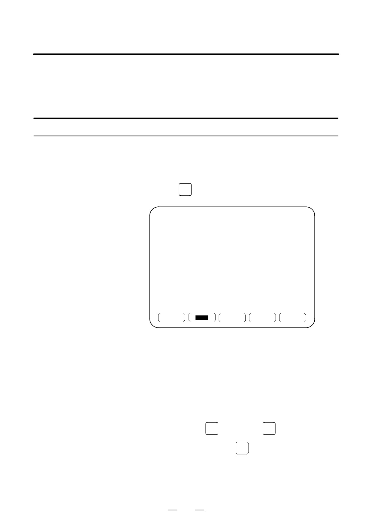
PROGRAM ( MDI )
0010
00002
O0000;
G00
G90
G94
G40
G80
G50
G54
G69
G17
G22
G21
G49
G98
G67
G64
G15
B HM
T
D
F
S
>_
MDI
* * * *
* * *
* * *
20 : 40 : 05
PRGRM
MDI
CURRNT
NEXT
(OPRT)
Program number O0000 is entered automatically.
3
Prepare a program to be executed by an operation similar to normal
program editing. M99 specified in the last block can return control to
the beginning of the program after operation ends. Word insertion,
modification, deletion, word search, address search, and program
search are available for programs created in the MDI mode. For
program editing, see Chapter III-9.
4
To entirely erase a program created in MDI mode,use one of the
following methods:
a. Enter address
O
, then press the
DELETE
key on the MDI panel.
b. Alternatively, press the
RESET
key. In this case, set bit 7 of
parameter 3203 to 1 in advance.
516
B-63524EN/01
OPERATION
4. AUTOMATIC OPERATION
5
To execute a program, set the cursor on the head of the program. (Start
from an intermediate point is possible.) Push Cycle Start button on
the operator’s panel. By this action, the prepared program will start.
(For the two-path control, select the tool post to be operated with the
tool post selection switch on the machine operator’s panel
beforehand.)
When the program end (M02, M30) or ER (%) is executed, the
prepared program will be automatically erased and the operation will
end.
By command of M99, control returns to the head of the prepared
program.
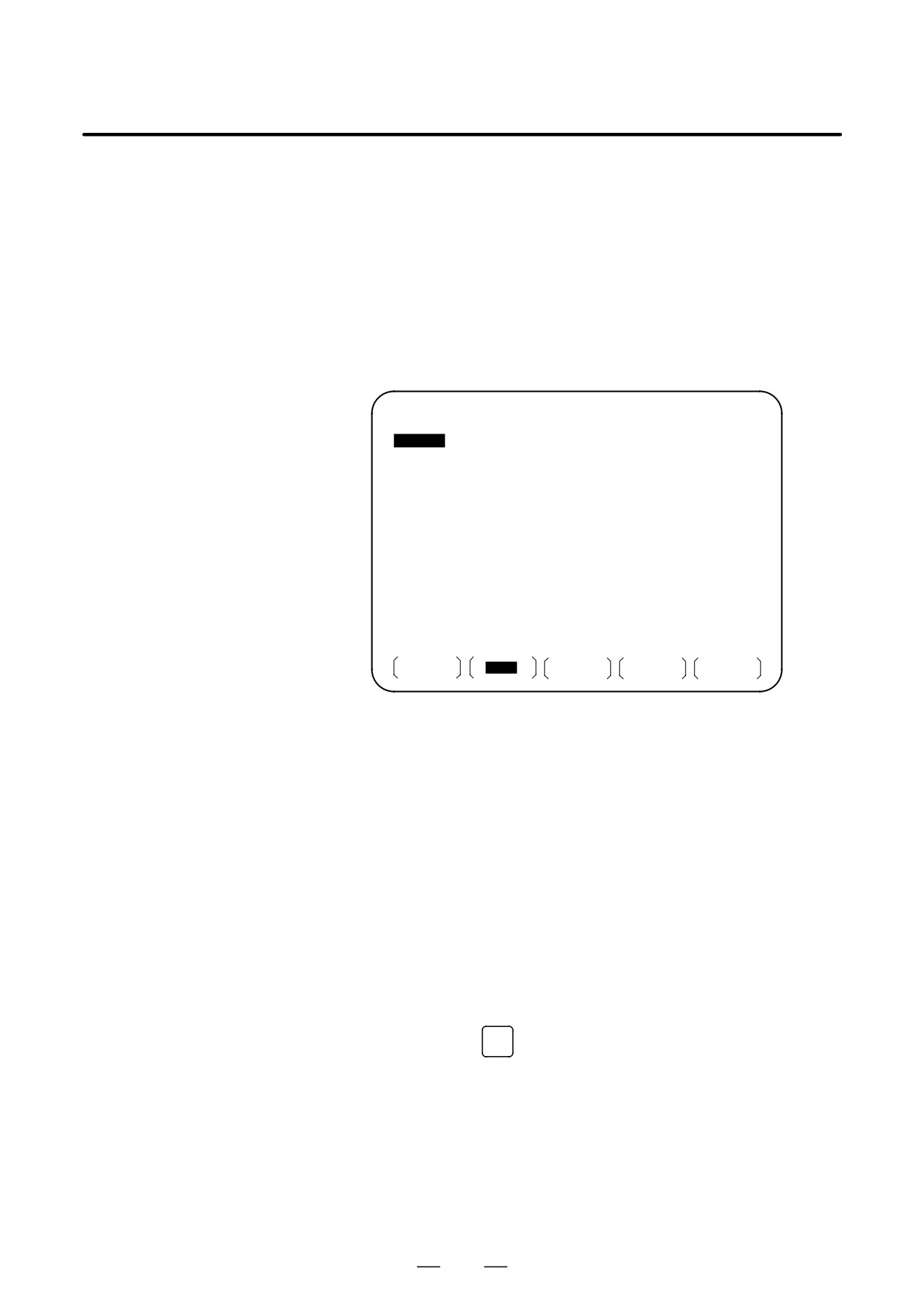
PROGRAM ( MDI )
O0001 N00003
O0000
G00 X100.0 Z200. ;
M03 ;
G01 Z120.0 F500 ;
M93 P9010 ;
G00 Z0.0 ;
%
G00
G90
G94
G40
G80
G50
G54
G69
G17
G22
G21
G49
G98
G67
G64
G15
B HM
T
D
F
S
>_
MDI
* * * *
* * *
* * *
12 : 42 : 39
PRGRM
MDI
CURRNT
NEXT
(OPRT)
6
To stop or terminate MDI operation in midway through, follow the
steps below.
a. Stopping MDI operation
Press the feed hold switch on the machine operator’s panel. The
feed hold LED goes on and the cycle start LED goes off. The
machine responds as follows:
(i) When the machine was moving, feed operation decelerates
and stops.
(ii) When dwell was being performed, dwell is stopped.
(iii) When M, S, or T was being executed, the operation is
stopped after M, S, or T is finished.
When the cycle start switch on the machine operator’s panel
is pressed, machine operation restarts.
b. Terminating MDI operation
Press the
RESET
key on the MDI panel.
Automatic operation is terminated and the reset state is entered.
When a reset is applied during movement, movement
decelerates then stops.
517
4. AUTOMATIC OPERATION
OPERATION
B-63524EN/01
Explanation
The previous explanation of how to execute and stop memory operation
also applies to MDI operation, except that in MDI operation, M30 does
not return control to the beginning of the program (M99 performs this
function).
D Erasing the program
Programs prepared in the MDI mode will be erased in the following cases:
D In MDI operation, if M02, M30 or ER(%) is executed.
(If bit 6 (MER) of parameter No. 3203 is set to 1, however, the program
is erased when execution of the last block of the program is completed
by single-block operation.)
D In MEMORY mode, if memory operation is performed.
D In EDIT mode, if any editing is performed.
D Background editing is performed.
D When the
O
and
DELETE
key are pressed,
D Upon reset when bit 7 (MCL) of parameter No. 3203 is set to 1
D Restart
After the editing operation during the stop of MDI operation was done,
operation starts from the current cursor position.
D Editing a program during
A program can be edited during MDI operation. The editing of a program,
MDI operation
however, is disabled until the CNC is reset, when bit 5 (MIE) of parameter
No. 3203 is set accordingly.
Limitation
D Program registration
Programs created in MDI mode cannot be registered.
D Number of lines in a
A program can have as many lines as can fit on one page of the screen.
program
A program consisting of up to six lines can be created. When parameter
MDL (No. 3107 #7) is set to 0 to specify a mode that suppresses the
display of continuous-state information, a program of up to 10 lines can
be created.
If the created program exceeds the specified number of lines, % (ER) is
deleted (prevents insertion and modification).
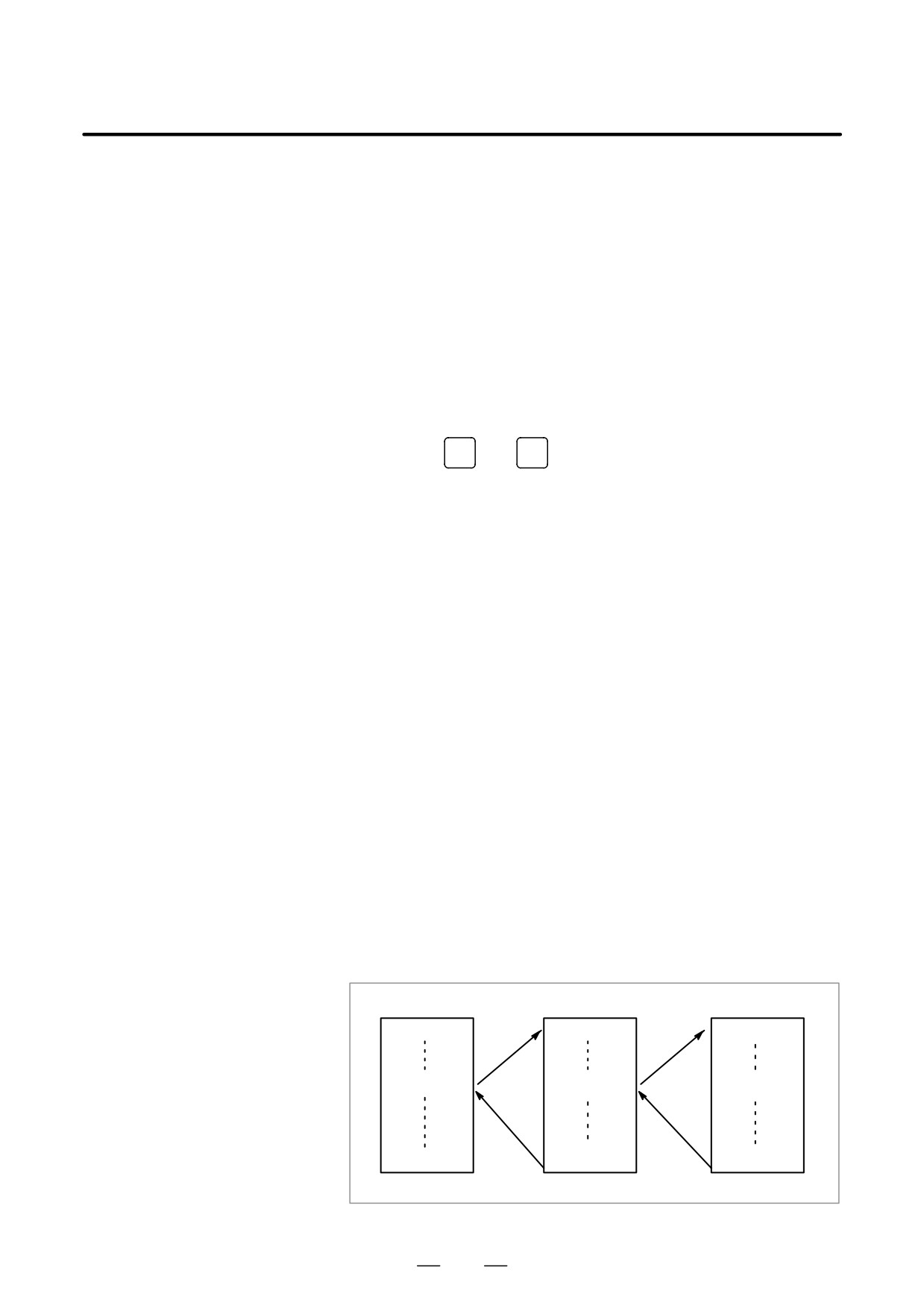
D Subprogram nesting
Calls to subprograms (M98) can be specified in a program created in the
MDI mode. This means that a program registered in memory can be
called and executed during MDI operation. In addition to the main
program executed by automatic operation, up to two levels of subprogram
nesting are allowed (when the custom macro option is provided, up to four
levels are allowed).
Main program
Subprogram
Subprogram
O0000;
O1000;
O2000;
M98P 1000;
M98P 2000;
M98P 3000;
M30;
M99;
M99;
One-level nesting
Two-level nesting
Fig. 4.2 Nesting Level of Subprograms Called from the MDI Program
518