FANUC Series Series 16i-TB, Series 18i-TB, Series 160i-TB, Series 180i-TB. OPERATOR’S MANUAL - page 8
13. FUNCTIONS TO SIMPLIFY
B-63524EN/01
PROGRAMMING
PROGRAMMING
Examples
M51 ;
Setting C-axis index mode ON
M3 S2000 ;
Rotating the drill
G00 X50.0 C0.0 ;
Positioning the drill along the X- and
C-axes
G83 Z-40.0 R-5.0 P500 F5.0 M31 ; Drilling hole 1
C90.0 M31 ;
Drilling hole 2
C180.0 M31 ;
Drilling hole 3
C270.0 M31 ;
Drilling hole 4
G80 M05 ;
Canceling the drilling cycle and
stopping drill rotation
M50 ;
Setting C-axis index mode off
13.3.2
This cycle performs tapping.
In this tapping cycle, when the bottom of the hole has been reached, the
Front Tapping Cycle
spindle is rotated in the reverse direction.
(G84) / Side Tapping
Cycle (G88)
Format
G84 X(U)_ C(H)_ Z(W)_ R_ P_ F_ K_ M_ ;
or
G88 Z(W)_ C(H)_ X(U)_ R_ P_ F_ K_ M_ ;
X_ C_ or Z_ C_ : Hole position data
Z_ or X_
: The distance from point R to the bottom of the hole
R_ : The distance from the initial level to point R level
P_ : Dwell time at the bottom of a hole
F_ : Cutting feedrate
K_ : Number of repeats (When it is needed.)
M_ : M code for C-axis clamp (when it is needed.)
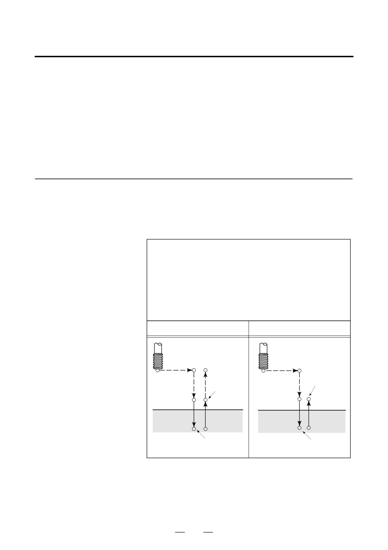
G84 or G88 (G98 mode)
G84 or G88 (G99 mode)
Mα
Initial level
Mα
Spindle CW
Spindle CW
M (a+1), P2
M (a+1), P2
Point R
Point R level
Point R
Point Z
Point Z
P1
P1
Spindle CCW
Spindle CCW
Explanations
Tapping is performed by rotating the spindle clockwise. When the bottom
of the hole has been reached, the spindle is rotated in the reverse direction
for retraction. This operation creates threads.
Feedrate overrides are ignored during tapping. A feed hold does not stop
the machine until the return operation is completed.
189
13. FUNCTIONS TO SIMPLIFY
PROGRAMMING
PROGRAMMING
B-63524EN/01
NOTE
Bit 6 (M5T) of parameter No. 5101 specifies whether the
spindle stop command (M05) is issued before the direction
in which the spindle rotates is specified with M03 or M04.
For details, refer to the operator’s manual created by the
machine tool builder.
Examples
M51
;
Setting C-axis index mode ON
M3 S2000 ;
Rotating the drill
G00 X50.0 C0.0 ;
Positioning the drill along the X- and
C- axes
G83 Z-40.0 R-5.0 P500 F5.0 M31 ; Drilling hole 1
C90.0 M31 ;
Drilling hole 2
C180.0 M31 ;
Drilling hole 3
C270.0 M31 ;
Drilling hole 4
G80 M05 ;
Canceling the drilling cycle and
stopping drill rotation
M50 ;
Setting C-axis index mode off
190
13. FUNCTIONS TO SIMPLIFY
B-63524EN/01
PROGRAMMING
PROGRAMMING
13.3.3
This cycle is used to bore a hole.
Front Boring Cycle
(G85) / Side Boring
Cycle (G89)
Format
G85 X(U)_ C(H)_ Z(W)_ R_ P_ F_ K_ M_ ;
or
G89 Z(W)_ C(H)_ X(U)_ R_ P_ F_ K_ M_ ;
X_ C_ or Z_ C_ : Hole position data
Z_ or X_
: The distance from point R to the bottom of the hole
R_ : The distance from the initial level to point R level
P_ : Dwell time at the bottom of a hole
F_ : Cutting feedrate
K_ : Number of repeats (When it is needed.)
M_ : M code for C-axis clamp (When it is needed.)
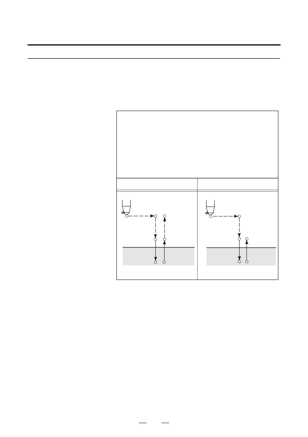
G85 or G89 (G98 mode)
G85 or G89 (G99 mode)
Mα
Initial level
Mα
Point R level
M (a)1), P2
Point R
Point R
M (a)1), P2
Point Z
Point Z
P1
P1
Explanations
After positioning, rapid traverse is performed to point R.
Drilling is performed from point R to point Z.
After the tool reaches point Z, it returns to point R at a feedrate twice the
cutting feedrate.
Examples
M5 1 ;
Setting C-axis index mode ON
M3 S2000 ;
Rotating the drill
G00 X50.0 C0.0 ;
Positioning the drill along the X- and
C-axes
G83 Z-40.0 R-5.0 P500 F5.0 M31 ; Drilling hole 1
C90.0 M31 ;
Drilling hole 2
C180.0 M31 ;
Drilling hole 3
C270.0 M31 ;
Drilling hole 4
G80 M05 ;
Canceling the drilling cycle and
stopping drill rotation
M50 ;
Setting C-axis index mode off
191

13. FUNCTIONS TO SIMPLIFY
PROGRAMMING
PROGRAMMING
B-63524EN/01
13.3.4
G80 cancels canned cycle.
Canned Cycle for
Drilling Cancel (G80)
Format
G80 ;
Explanations
Canned cycle for drilling is canceled to perform normal operation.
Point R and point Z are cleared. Other drilling data is also canceled
(cleared).
Examples
M51 ;
Setting C-axis index mode ON
M3 S2000 ;
Rotating the drill
G00 X50.0 C0.0 ;
Positioning the drill along the X- and
C-axes.
G83 Z-40.0 R-5.0 P500 F5.0 M31 ; Drilling hole 1
C90.0 M31 ;
Drilling hole 2
C180.0 M31 ;
Drilling hole 3
C270.0 M31 ;
Drilling hole 4
G80 M05 ;
Canceling the drilling cycle and
stopping drill rotation
M50 ;
Setting C-axis index mode off
192
13. FUNCTIONS TO SIMPLIFY
B-63524EN/01
PROGRAMMING
PROGRAMMING
13.3.5
Precautions to be
Taken by Operator
D Reset and emergency
Even when the controller is stopped by resetting or emergency stop in the
stop
course of drilling cycle, the drilling mode and drilling data are saved ; with
this mind, therefore, restart operation.
D Single block
When drilling cycle is performed with a single block, the operation stops
at the end points of operations 1, 2, 6 in Fig. 13.3 (a).
Consequently, it follows that operation is started up 3 times to drill one
hole. The operation stops at the end points of operations 1, 2 with the feed
hold lamp ON. The operation stops in the feed hold conditions at the end
point of operation 6 if the repeat remains, and it stops in stop conditions
in other cases.
D Feed hold
When “Feed Hold” is applied between operations 3 and 5 by G84/G88,
the feed hold lamp lights up immediately if the feed hold is applied again
to operation 6.
D Override
During operation with G84 and G88, the feedrate override is 100%.
193
13. FUNCTIONS TO SIMPLIFY
PROGRAMMING
PROGRAMMING
B-63524EN/01
There are four grinding canned cycles : the traverse grinding cycle (G71),
13.4
traverse direct fixed-dimension grinding cycle, oscillation grinding
CANNED GRINDING
cycle, and oscillation direct fixed-dimension grinding cycle.
CYCLE
With a machine tool that allows canned cycles for grinding to be used, the
multiple repetitive canned cycle for turning cannot be used.
(FOR GRINDING
MACHINE)
13.4.1
Traverse Grinding
Cycle (G71)
Format
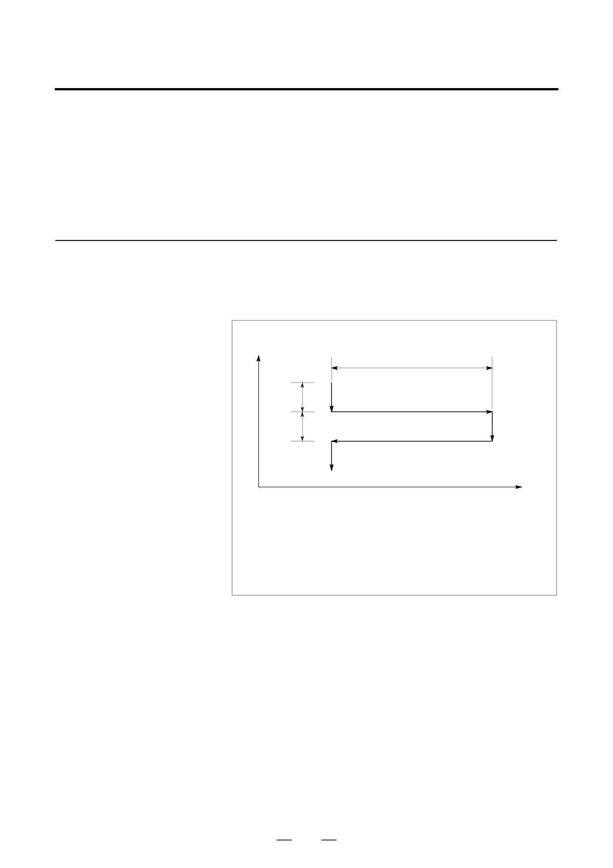
G71 A_ B_ W_ U_ I_ K_ H_ ;
X
W
(1) (I)
A
(3) (K)
(2)
U(dwell)
(4) (I)
B
(5)(dwell)
(6) (K)
Z
A : First depth of cut
B : Second depth of cut
W : Grinding range
U : Dwell time Maximum specification time : 99999.999 seconds
I : Feedrate of A and B
K : Feedrate of W
H : Number of repetitions Setting value : 1 to 9999
Explanations
The specification ranges and units of the canned cycle for grinding are
described below.
Move command Range : ±8 digits
Units : 1 µm/0.0001 inch
Feedrate Range
Feed per minute : 0.001 to 240000 mm/min
0.0001 to 9600 inch/min
(for 1 µm/0.0001 inch)
Feed per revolution :
0.00001 to 500 mm/rev
0.00001 to 9 inch/rev
A, B, and W are to be specified in an incremental mode.
In the case of a single block, the operations 1, 2, 3, 4, 5, and 6 are
performed with one cycle start operation.
A=B=0 results in a spark-out.
194
13. FUNCTIONS TO SIMPLIFY
B-63524EN/01
PROGRAMMING
PROGRAMMING
13.4.2
Traverse Direct
Fixed-dimension
Grinding Cycle (G72)
Format
G72 P_ A_ B_ W_ U_ I_ K_ H_ ;
P : Gauge number (1 to 4)
A : First depth of cut
B : Second depth of cut
W : Grinding range
U : Dwell time Maximum specification time : 99999.999seconds
I : Feedrate of A and B
K : Feedrate of W
H : Number of repetitions Setting value : 1 to 9999
Explanations
When the multistage skip operation is used, a gauge number can be
specified. The method of gauge number specification is the same as the
method of multistage skip function. When the multistage skip operation
is not used, the conventional skip signal is valid.
The same specifications as G71 apply except for gauge number
specification.
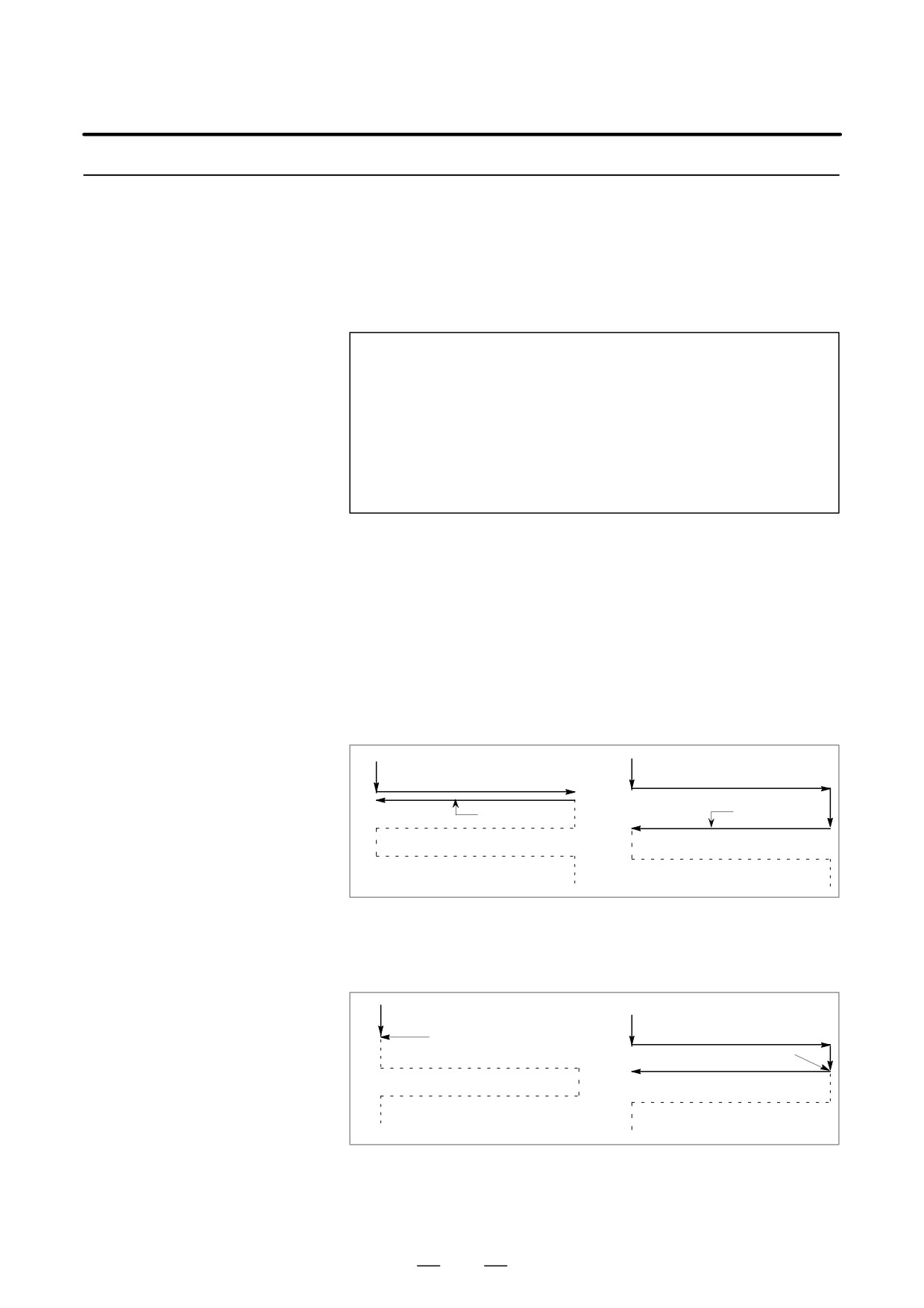
D Operation at the time of
1. When the tool moves along the Z-axis to grind a workpiece, if a skip
skip signal input
signal is input, the tool returns to the Z coordinate where the cycle
started after the tool reaches the end of the specified grinding area.
(Termination)
(Skip signal)
(Skip signal)
(Termination)
2. When the tool cuts a workpiece along the X-axis, if a skip signal is
input, the tool stops cutting immediately and returns to the Z
coordinate where the cycle started.
(Skip signal)
(Termination)
(Skip signal)
(Termination)
3. The skip signal is valid during dwell, without being affected by
parameters DS1 to DS8 (No. 6206#0 to #7). Dwell is immediately
stopped for return to the Z axis coordinate where the cycle started.
195
13. FUNCTIONS TO SIMPLIFY
PROGRAMMING
PROGRAMMING
B-63524EN/01
13.4.3
Oscillation Grinding
Cycle (G73)
Format
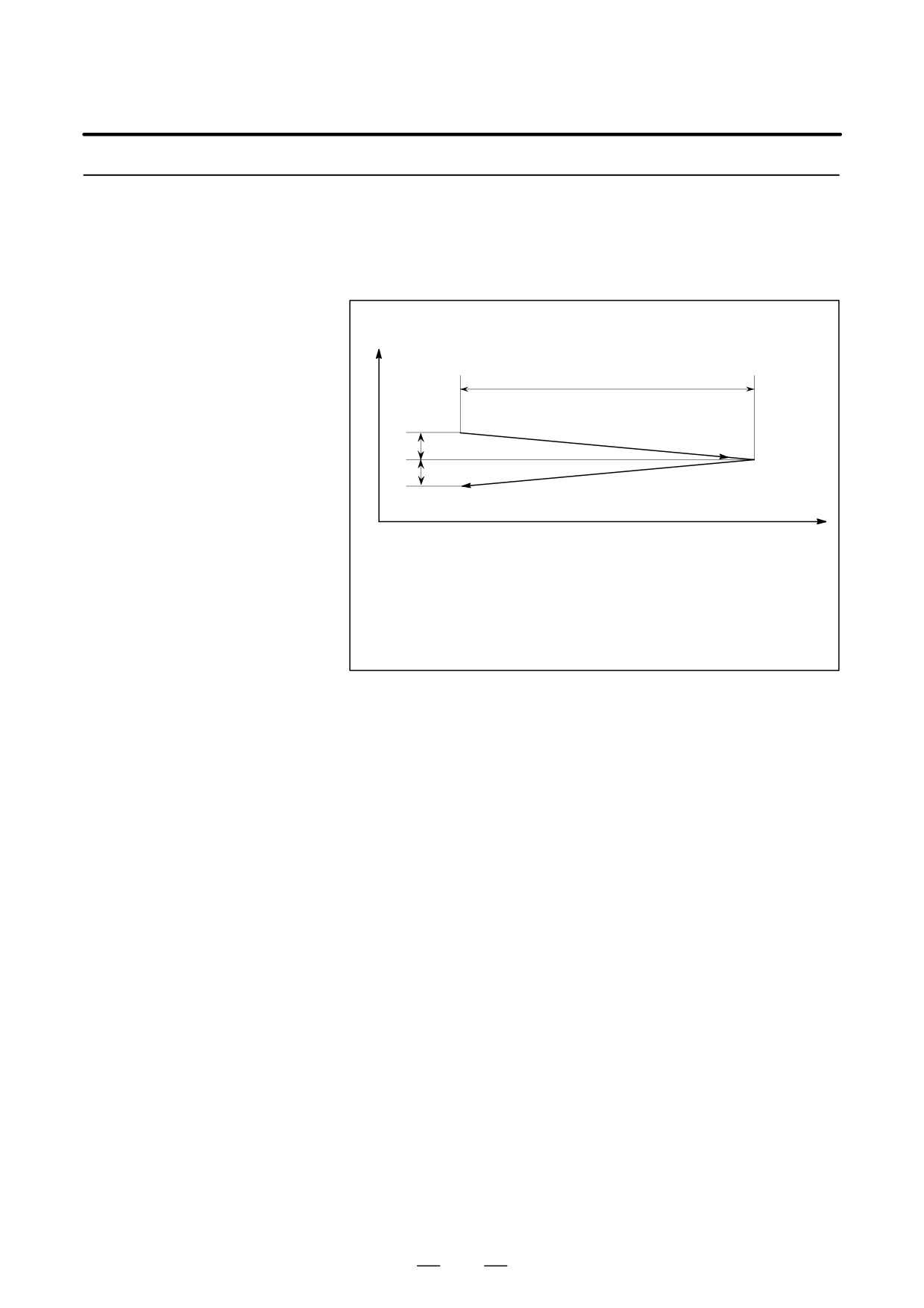
G73 A_ (B_) W_ U_ K_ H_ ;
Z
W
(1)
(2) (K)
U (dwell)
A
U (dwell)
(3)
(B)
(4) (K)
X
A : Depth of cut
B : Depth of cut
W : Grinding range
U : Dwell time
K : Feedrate
H : Number of repetitions Setting value : 1A9999
Explanations
A, B, and W are to be specified in an incremental mode.
In the case of a single block, the operations 1, 2, 3, and 4 are performed
with one cycle start operation.
The specification of B is valid only for a specified block. This is not
associated with B of the G71 or G72 cycle.
196
13. FUNCTIONS TO SIMPLIFY
B-63524EN/01
PROGRAMMING
PROGRAMMING
13.4.4
Oscillation Direct
Fixed-Dimension
Grinding Cycle
Format
G74 P_ A_ (B_) W_ U_ K_ H_ ;
P : Gauge number (1 to 4)
A : Depth of cut
B : Depth of cut
W : Grinding range
U : Dwell time
K : Feedrate of W
H : Number of repetitions Setting value : 1 to 9999
Explanations
When the multistage skip operation is used, a gauge number can be
specified. The method of gauge number specification is the same as the
method of multistage skip function. When the multistage skip operation
is not used, the conventional skip signal is valid.
The same specifications as G73 apply to the other items.
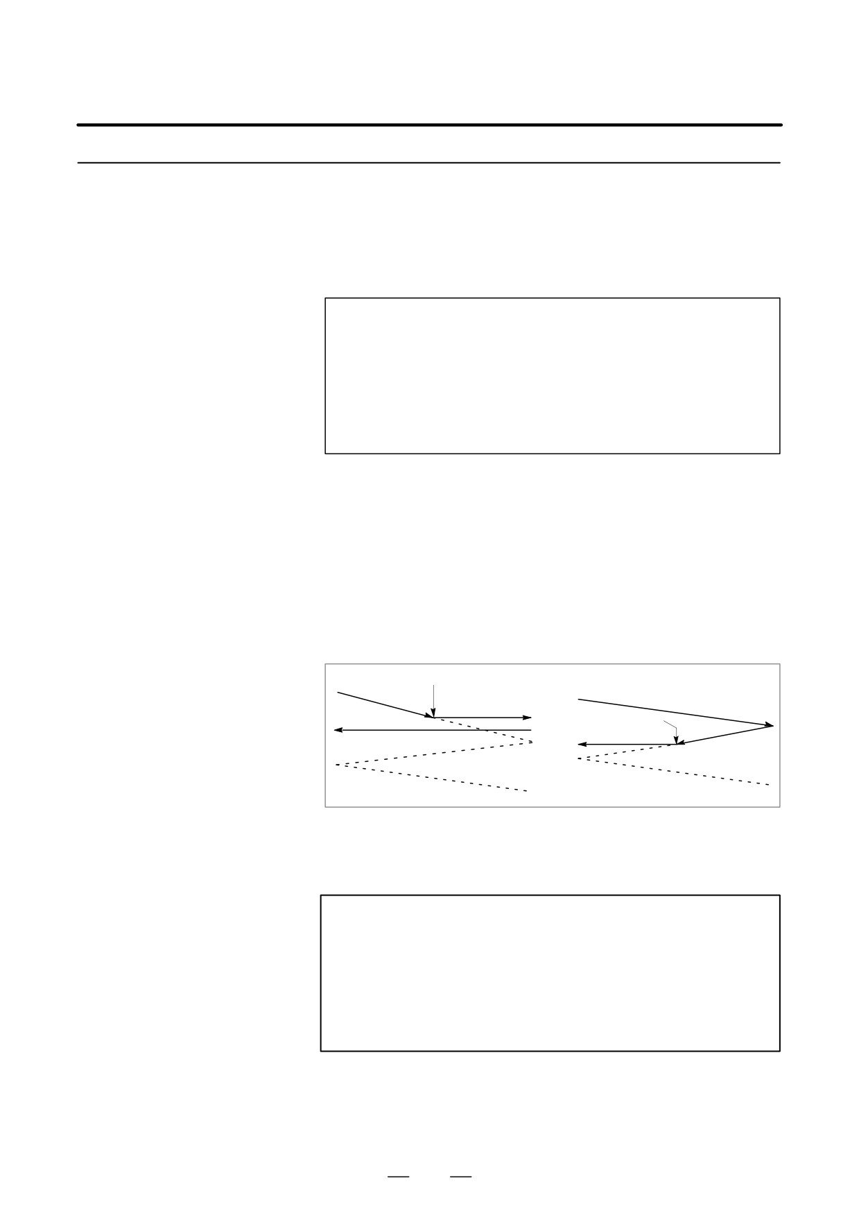
D Operation at the time of
1. When the tool moves along the Z-axis to grind a workpiece, if a skip
skip signal input
signal is input, the tool returns to the Z coordinate where the cycle
started after the tool reaches the end of the specified grinding area.
Skip signal
Skip signal
(Termination)
(Termination)
2. The skip signal is valid during dwell, without being affected by
parameters DS1 to DS8 (No. 6206#0 to #7). Dwell is immediately
stopped for return to the Z axis coordinate where the cycle started.
NOTE
1
The data items A, B, W, I, and K in a canned cycle are modal
values common to G71 through G74. The data items A, B,
W, U, I and K are cleared when a one-shot G code other
than G04 or a 01 group G code other than G71 to G74 is
specified.
2
No B code can be specified in the canned cycle mode.
197
13. FUNCTIONS TO SIMPLIFY
PROGRAMMING
PROGRAMMING
B-63524EN/01
A chamfer or corner can be inserted between two blocks which intersect
13.5
at a right angle as follows :
CHAMFERING AND
CORNER R
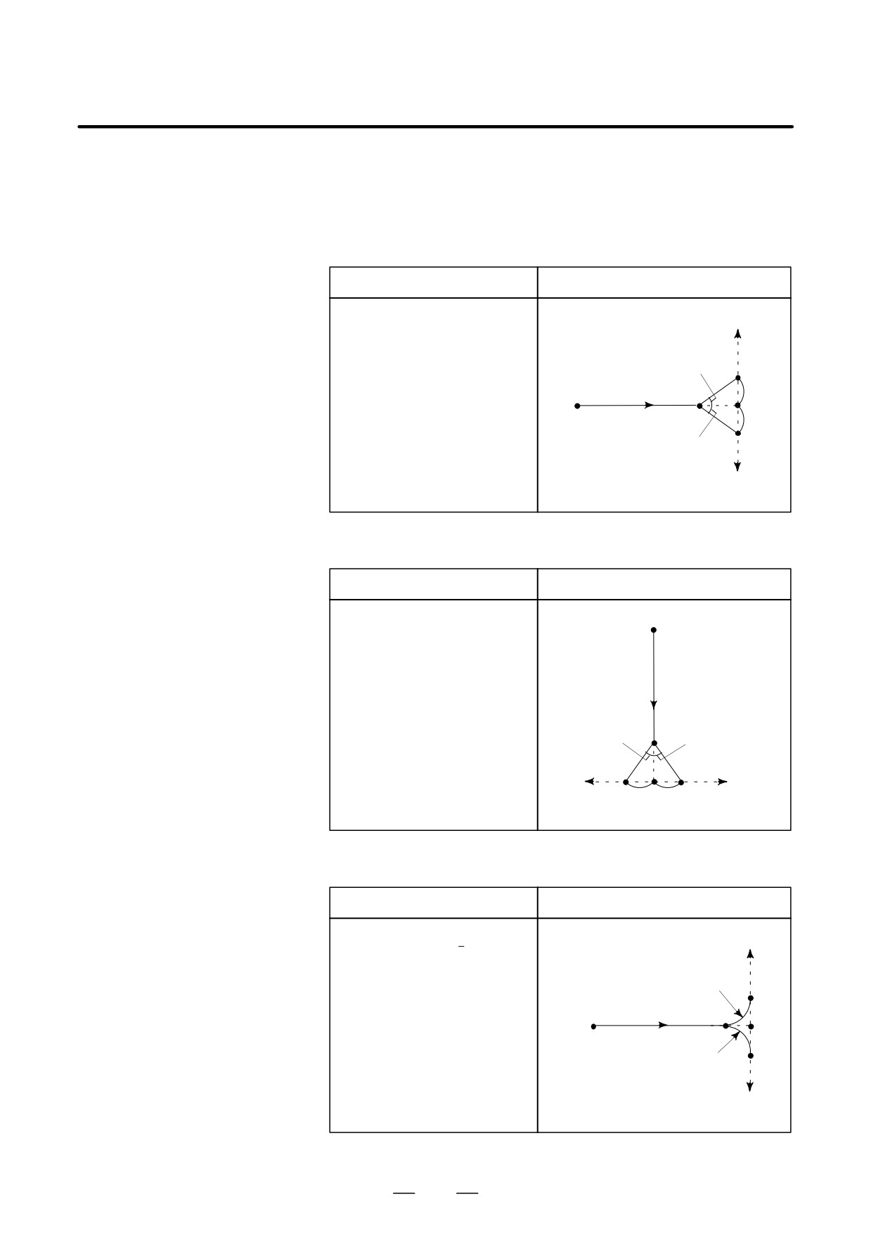
D Chamfering
Z → X
Format
Tool movement
G01 Z(W) _ I (C) ±i ;
+x
Specifies movement to point
b with an absolute or incremental
45°
command in the figure on the
c
right.
i
a
d
b
Start point
-i
c
45°
Moves as
a→d→c
-x
(For -X movement, -i)
Fig. 13.5 (a) Chamfering (Z→X)
D Chamfering
X → Z
Format
Tool movement
Start point
G01 X(U) _ K (C) ±k ;
a
Moves as
Specifies movement to point
a→d→c
b with an absolute or incremental
command in the figure on the
right.
d
45°
45°
-z
+z
c
b
c
-k
k
(For -Z movement, -k)
Fig. 13.5 (b) Chamfering (X→Z)
D Corner R
Z → X
Format
Tool movement
G01 Z(W) _ R ±r ;
+x
Specifies movement to point
b with an absolute or incremental
r
command in the figure on the
c
right.
a
d
b
Start point
c
-r
Moves as
a→d→c
-x
(For -X movement, -r)
Fig. 13.5 (c) Corner R (Z→X)
198
13. FUNCTIONS TO SIMPLIFY
B-63524EN/01
PROGRAMMING
PROGRAMMING
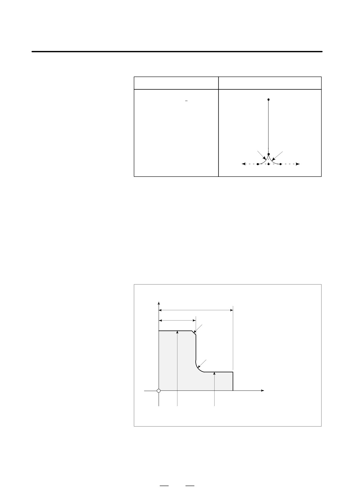
D Corner R
X → Z
Format
Tool movement
Start point
G01 X(U) _ R ±r ;
a
Specifies movement to point
b with an absolute or incremental
(For -x movement,
Moves as
command in the figure on the
-r)
a→d→c
right.
-r
d
r
-z
+z
c
b c
Fig. 13.5 (d) Corner R (X→Z)
Explanations
The movement for chamfering or corner R must be a single movement
along the X or Z axis in G01 mode. The next block must be a single
movement along the X or Z axis perpendicular to the former block.
I or K, and R always specify a radius value.
Note that the start point for a command specified in a block following a
chamfering or corner-R block is not point c but point b shown in Figs.
13.5 (a) to (d). In incremental programming, specify a distance from point
b.
Examples
N1Z270.0R6.0;
X
N2X860.0K-3.0;
530.0
N3Z0;
270.0
C3
N3
N2
R6
N1
Z
φ860
φ268
199

13. FUNCTIONS TO SIMPLIFY
PROGRAMMING
PROGRAMMING
B-63524EN/01
NOTE
1
The following commands cause an alarm.
1) One of I, K, or R is commanded when X and Z axes are
specified by G01.
(P/S alarm No. 054)
2) Move amount of X or Z is less than chamfering value and
corner R value in the block where chamfering and corner
R are specified.
(P/S alarm No. 055)
3) Next block to the block where chamfering and corner R
were specified, has not G01 command. (P/S alarm No.
051, 052)
4) If more than one of I, K, and R are specified in G01, P/S
alarm No. 053 is issued.
2
A single block stops at point c in Fig. 13.5 (a) — (d) not at
point d.
3
Chamfering and corner R cannot be applied to a thread
cutting block.
4
C can be used instead of I or K as an address for chamfering
on the system which does not use C as an axis name. To
use C for an address for chamfering, fix parameter CCR No.
3405#4 to 1.
5
If both C and R are specified with G01 in a block, the
address specified last is valid.
6
Neither chamfering nor corner-R machining can be
specified in direct drawing dimension programming.
200
13. FUNCTIONS TO SIMPLIFY
B-63524EN/01
PROGRAMMING
PROGRAMMING
13.6
MIRROR IMAGE FOR
DOUBLE TURRET
(G68, G69)
Format
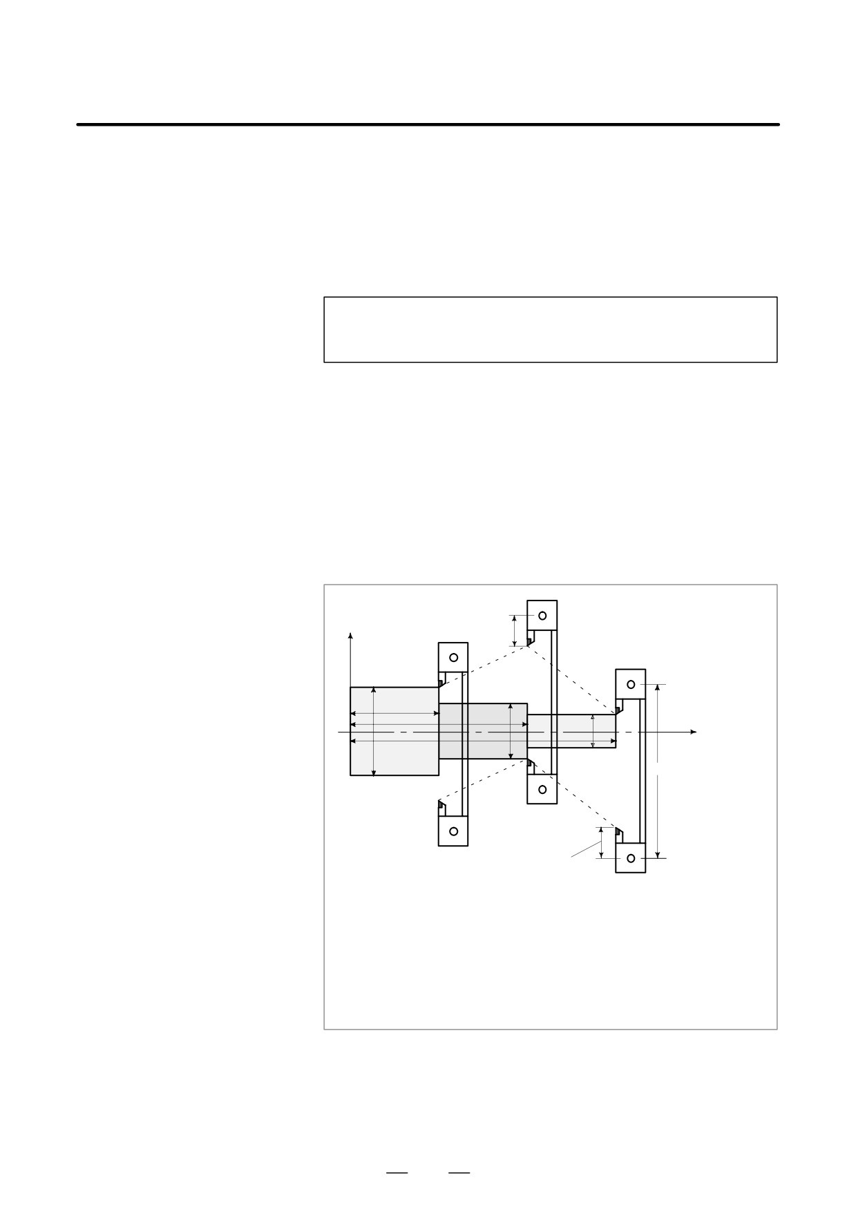
G68 : Double turret mirror image on
G69 : Mirror image cancel
Explanations
Mirror image can be applied to X-axis with G code.
When G68 is designated, the coordinate system is shifted to the mating
turret side, and the X-axis sign is reversed from the programmed
command to perform symmetrical cutting. To use this function, set the
distance between the two turrets to a parameter (No. 1290).
Examples
D Double turret
programming
X
Offset value of
tool post A
Tool post A
(3)
60
120
80φ
(1)
40φ
Z
180
120φ
120
(2)
Offset value of
tool post B
Tool post B
X40.0 Z180.0 T0101 ; Position turret A at (1)
G68 ;
Shift the coordinate system by the distance A to B
(120mm), and turn mirror image on.
X80.0 Z120.0 T0202 ; Position turret B at (2)
G69 ;
Shift the coordinate system by the distance B to A,
and turn mirror image cancel.
X120.0 Z60.0 T0101 ; Position turret A at (3)
201
13. FUNCTIONS TO SIMPLIFY
PROGRAMMING
PROGRAMMING
B-63524EN/01
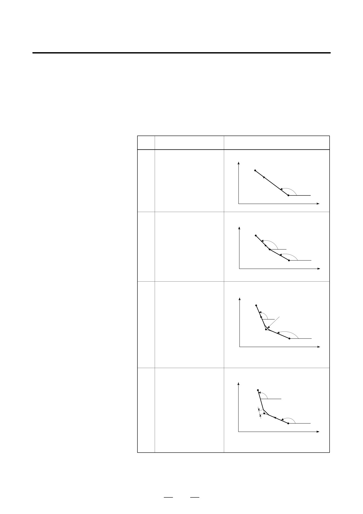
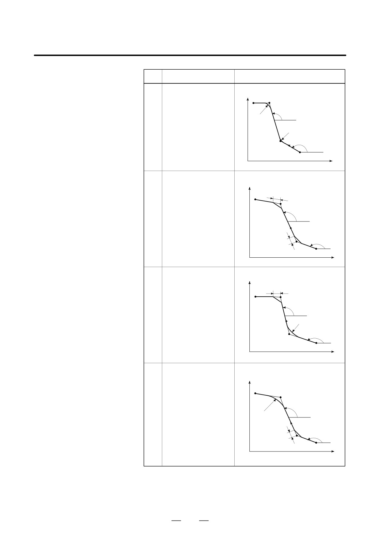
Angles of straight lines, chamfering value, corner rounding values, and
13.7
other dimensional values on machining drawings can be programmed by
DIRECT DRAWING
directly inputting these values. In addition, the chamfering and corner
DIMENSIONS
rounding can be inserted between straight lines having an optional angle.
PROGRAMMING
This programming is only valid in memory operation mode.
Format
Table 13.7 Commands table
Commands
Movement of tool
X
X2_ (Z2_), A_ ;
(X2 , Z2)
1
A
(X1 , Z1)
Z
X
,A1_
;
X
3_ Z3_, A2_ ;
(X3 , Z3)
A2
2
A1
(X2 , Z2)
(X1 , Z1)
Z
X2_ Z2_, R1_ ;
X
X3_ Z3_ ;
(X3 , Z3)
or
,A1_, R1_ ;
A2
R
X3_ Z3_, A2_ ;
3
1
A1
(X2 , Z2)
(X1 , Z1)
Z
X
X2_ Z2_, C1_ ;
X3_ Z3_ ;
(X3 , Z3)
or
A2
,A1_, C1_ ;
X3_ Z3_, A2_ ;
4
C1
A1
(X2 , Z2)
(X1 , Z1)
Z
202
13. FUNCTIONS TO SIMPLIFY
B-63524EN/01
PROGRAMMING
PROGRAMMING
Commands
Movement of tool
X
X2_ Z2_ , R1_ ;
(X4 , Z4)
(X3 , Z3)
X3_ Z3_ , R2_ ;
X4_ Z4_ ;
A2
or
R2
5
,A1_, R1_ ;
X3_ Z3_, A2_, R2_ ;
R
X4_ Z4_ ;
1
A1
(X2 , Z2)
(X1 , Z1)
Z
X
X2_ Z2_ , C1_ ;
X3_ Z3_ , C2_ ;
C2
X4_ Z4_ ;
or
(X4 , Z4)
(X3 , Z3)
,A1_, C1_ ;
A2
6
X3_ Z3_, A2_, C2_ ;
X4_ Z4_ ;
(X2 , Z2)
C1
A1
(X1 , Z1)
Z
X
X2_ Z2_ , R1_ ;
X3_ Z3_ , C2_ ;
C2
X4_ Z4_ ;
(X3 , Z3)
(X4 , Z4)
or
,A1_, R1_ ;
A2
7
X3_ Z3_, A2_, C2_ ;
X4_ Z4_ ;
R
1
A1
(X2 , Z2)
(X1 , Z1)
Z
X
X2_ Z2_ , C1_ ;
X3_ Z3_ , R2_ ;
(X4 , Z4)
X4_ Z4_ ;
(X3 , Z3)
or
,A1_, C1_ ;
A2
8
R2
X3_ Z3_, A2_, R2_ ;
X4_ Z4_ ;
(X2 , Z2)
C1
A1
(X1 , Z1)
Z
203
13. FUNCTIONS TO SIMPLIFY
PROGRAMMING
PROGRAMMING
B-63524EN/01
Explanations
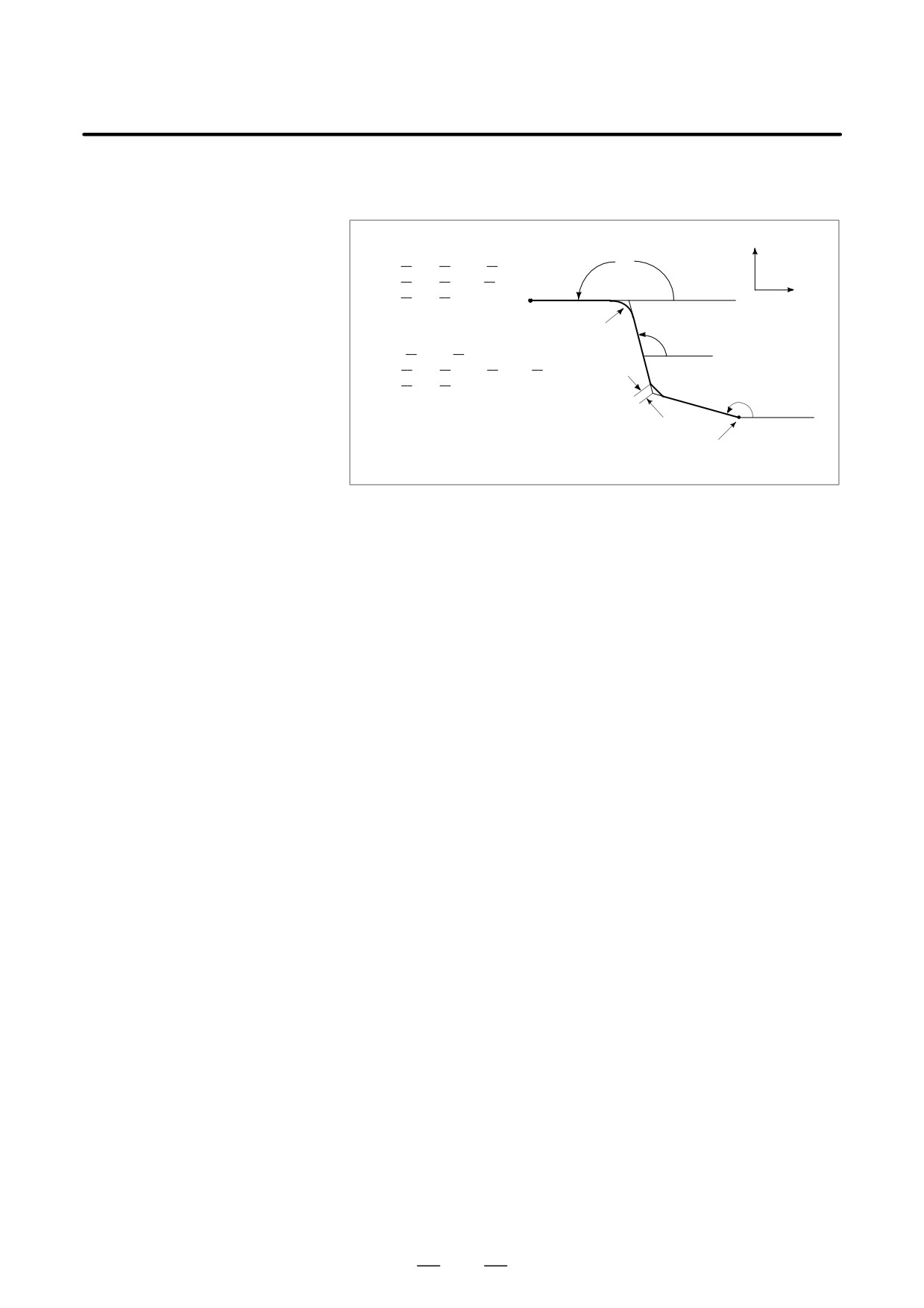
A program for machining along the curve shown in Fig. 13.7 (a) is as
follows :
+X
X (x2) Z (z2) , C (c1) ;
a3
X (x3) Z (z3) , R (r2) ;
X (x4) Z (z4) ;
(x3, z3)
+Z
(x4, z4)
o
r2
a2
,Ar(a1) , C (c1) ;
X (x3) Z (z3) , A (a2) , R (r2) ;
X (x4) Z (z4) ;
(x2, z2)
1
a
c1
(x1, z1)
Start point
Fig. 13.7 Machining Drawing (example)
For command a straight line, specify one or two out of X, Z, and A.
If only one is specified, the straight line must be primarily defined by a
command in the next block.
To command the degree of a straight line or the value of chamfering or
corner R, command with a comma (,) as follows :
, A_
, C_
, R_
By specifying 1 to parameter CCR No. 3405#4 on the system which does
not use A or C as an axis name, the degree of a straight line or the value
of chamfering or corner R can be commanded without a comma (,) as
follows :
A_
C_
R_
204

13. FUNCTIONS TO SIMPLIFY
B-63524EN/01
PROGRAMMING
PROGRAMMING
NOTE
1
The following G codes are not applicable to the same block
as commanded by direct input of drawing dimensions or
between blocks of direct input of drawing dimensions which
define sequential figures.
1) G codes (other than G04) in group 00.
2) G02, G03, G90, G92, and G94 in group 01.
2
Corner rounding cannot be inserted into a threading block.
3
Chamfering and corner R using the direct input of drawing
dimensions cannot be used simultaneously with the
chamfering and corner R described in Section 13.5.
(The
option for chamfering and corner R and that for the direct
input of drawing dimensions cannot be selected
simultaneously.)
4
When the end point of the previous block is determined in
the next block according to sequential commands of direct
input of drawing dimensions, the single block stop is not
done, but the feed hold stop is done at the end point of the
previous block.
5
The angle allowance in calculating the point of intersection
in the program below is ±1°.
(Because the travel distance to be obtained in this
calculation is too large.)
1) X_ , A_ ; (If a value within 0°±1°or 180°±1°is specified for
the angle instruction, the P/S alarm No.057 occurs.)
2) Z_ , A_ ; (If a value within 90°±1°or 270°±1°is specified
for the angle instruction, the P/S alarm No. 057 occurs.)
6
An alarm occurs if the angle made by the 2 lines is within
±1°when calculating the point of intersection.
7
Chamfering or corner % is ignored if the angle made by the
2 lines is within ±1°.
8
Both a dimensional command (absolute programming) and
angle instruction must be specified in the block following a
block in which only the angle instruction is specified.
(Example)
N1 X_, A_, R_ ;
N2, A_ ;
N3 X_ Z_, A_ ;
(In addition to the dimentional command, angle instruction
must be specified in block No. 3.)
205
13. FUNCTIONS TO SIMPLIFY
PROGRAMMING
PROGRAMMING
B-63524EN/01
Examples
X
R20
R15
R6
φ 300
φ 100
Z
φ 60
10°
1×45°
30
180
22°
(Diameter specification, metric input)
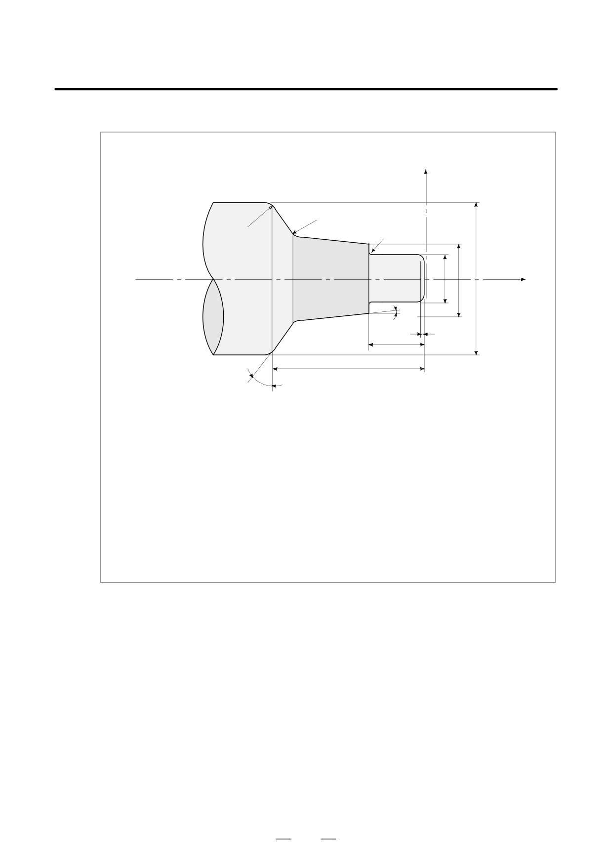
N001 G50 X0.0 Z0.0 ;
N002 G01 X60.0, A90.0, C1.0 F80 ;
N003 Z-30.0, A180.0, R6.0 ;
N004 X100.0, A90.0 ;
N005 ,A170.0, R20.0 ;
N006 X300.0 Z-180.0, A112.0, R15.0 ;
N007 Z-230.0, A180.0 ;
:
:
206
13. FUNCTIONS TO SIMPLIFY
B-63524EN/01
PROGRAMMING
PROGRAMMING
Front face tapping cycles (G84) and side face tapping cycles (G88) can
13.8
be performed either in conventional mode or rigid mode.
RIGID TAPPING
In conventional mode, the spindle is rotated or stopped, in
synchronization with the motion along the tapping axis according to
miscellaneous functions M03 (spindle CW rotation), M04 (spindle CCW
rotation), and M05 (spindle stop).
In rigid mode, the spindle motor is controlled in the same way as a control
motor, by the application of compensation to both motion along the
tapping axis and that of the spindle.
For rigid tapping, each turn of the spindle corresponds to a certain amount
of feed (screw lead) along the spindle axis. This also applies to
acceleration/deceleration. This means that rigid tapping does not demand
the use of float tappers as in the case of conventional tapping, thus
enabling high-speed, high-precision tapping.
When the system is equipped with the optional multispindle control
function, the second spindle can be used for rigid tapping.
207
13. FUNCTIONS TO SIMPLIFY
PROGRAMMING
PROGRAMMING
B-63524EN/01
13.8.1
Controlling the spindle motor in the same way as a servo motor in rigid
mode enables high-speed tapping.
Front Face Rigid
Tapping Cycle (G84) /
Side Face Rigid
Tapping Cycle (G88)
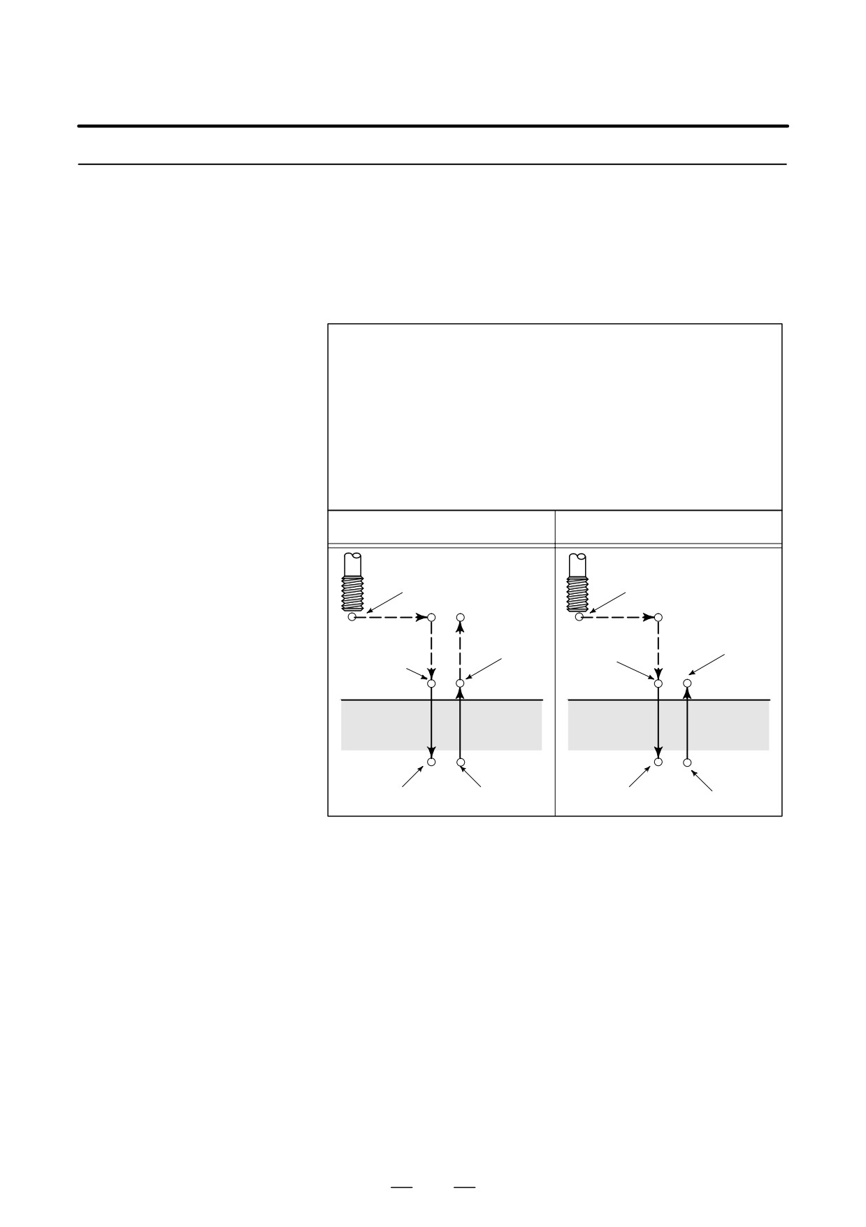
Format
G84 X(U)_ C(H)_ Z(W)_ R_ P_ F_ M_ K_ ;
or
G88 Z(W)_ C(H)_ X(U)_ R_ P_ F_ M_ K_ ;
X_ C_ or Z_ C_ : Hole position data
Z_ or X_
: The distance from point R to the bottom of the hole
R_ : The distance from the initial level to point R level
P_ : Dwell time at the bottom of a hole
F_ : Cutting feedrate
K_ : Number of repeats (When it is needed.)
M_ : M code for C-axis clamp (when it is needed.)
G84 or G88 (G98 mode)
G84 or G88 (G99 mode)
Spindle stop
Spindle stop
Initial level
Operation 1
Operation 6
Operation 2
Spindle stop
Spindle CW
Spindle
Spindle CW
P
P
stop
Point R level
Point R
Point R
Operation 3
Operation 5
Point Z
Point Z
P
P
Operation 4
Spindle stop
Spindle stop
Spindle CCW
Spindle CCW
Explanations
Once positioning for the X-axis (G84) or Z-axis (G88) has been
completed, the spindle is moved, by rapid traverse, to point R. Tapping
is performed from point R to point Z, after which the spindle stops and
observes a dwell time. Then, the spindle starts reverse rotation, retracts
to point R, stops rotating, then moves to the initial level by rapid traverse.
During tapping, the feedrate override and spindle override are assumed
to be 100%. For retraction (operation 5), however, a fixed override of up
to 2000% can be applied by setting parameter No. 5211 (RGOVR), bit 4
(DOV) of parameter No. 5200, and bit 3 (OVU) of parameter of No. 5201.
D Rigid mode
Rigid mode can be specified by applying any of the following methods:
D Specifying M29S***** before a tapping block
D Specifying M29S***** within a tapping block
D Handling G84 or G88 as a G code for rigid tapping (Set bit 0 (G84) of
parameter No. 5200 to 1.)
208

13. FUNCTIONS TO SIMPLIFY
B-63524EN/01
PROGRAMMING
PROGRAMMING
D Thread lead
In feed per minute mode, the feedrate divided by the spindle speed is equal
to the thread lead. In feed per rotation mode, the feedrate is equal to the
thread lead.
Limitations
D S commands
When a value exceeding the maximum rotation speed for the gear being
used is specified, P/S alarm No. 200 is issued. For an analog spindle,
when a command is specified such that more than 4095 pulses are
generated during 8 ms (detection unit), P/S alarm No. 202 is issued. For
a serial spindle, when a command is specified such that more than 32767
pulses are generated during 8 ms (detection unit), P/S alarm No. 202 is
issued.
<Example>
For a built-in motor equipped with a detector having a resolution of
4095 pulses per rotation, the maximum spindle speed during rigid
tapping is as follows:
For an analog spindle
(4095×1000÷8×60)÷4095 = 7500 (rpm)
For a serial spindle
(32767×1000÷8×60)÷4095 = 60012 (rpm) [Note: Ideal value]
D F commands
Specifying a value larger than the upper limit for cutting feed will cause
P/S alarm No. 201 to be issued.
D M29
Specifying an S command or axis movement between M29 and M84 will
cause P/S alarm No. 203 to be issued. Specifying M29 during a tapping
cycle will cause P/S alarm No. 204 to be issued.
D Rigid tapping command
The M code used to specify rigid tapping mode is usually set in parameter
M code
No. 5210. To set a value of more than 255, however, use parameter No.
5212.
D Maximum position
The maximum position deviation during movement along the tapping
deviation during
axis in rigid tapping mode is usually set in parameter No. 5310. Use
movement along the
parameter No. 5314, however, when setting a value of more than 32767,
tapping axis
for example, according to the resolution of the detector being used.
D R
The value of R must be specified in a block which performs drilling. If
the value is specified in a block which does not perform drilling, it is not
stored as modal data.
D Cancellation
G00 to G03 (G codes in group 01) must not be specified in a block
containing G84 or G88. If specified, G84 or G88 in that block is canceled.
D Tool position offset
Any tool position offset is ignored in canned cycle mode.
D Units for F
Metric input
Inch input
Remark
G98
1 mm/min
0.01inch/min
Decimal point allowed
G99
0.01mm/rev
0.0001inch/rev
Decimal point allowed
209
13. FUNCTIONS TO SIMPLIFY
PROGRAMMING
PROGRAMMING
B-63524EN/01
Examples
Tapping axis feedrate:
1000 mm/min
Spindle speed:
1000 min-1
Screw lead: 1.0 mm
<Programming for feed per minute>
G98 ;
Command for feed per minute
G00 X100.0 ;
Positioning
M29 S1000 ;
Command for specifying rigid mode
G84 Z-100.0 R-20.0 F1000 ; Rigid tapping
<Programming for feed per rotation>
G99 ;
Command for feed per rotation
G00 X100.0 ;
Positioning
M29 S1000 ;
Command for specifying rigid mode
G84 Z-100.0 R-20.0 F1.0 ;
Rigid tapping
210
13. FUNCTIONS TO SIMPLIFY
B-63524EN/01
PROGRAMMING
PROGRAMMING
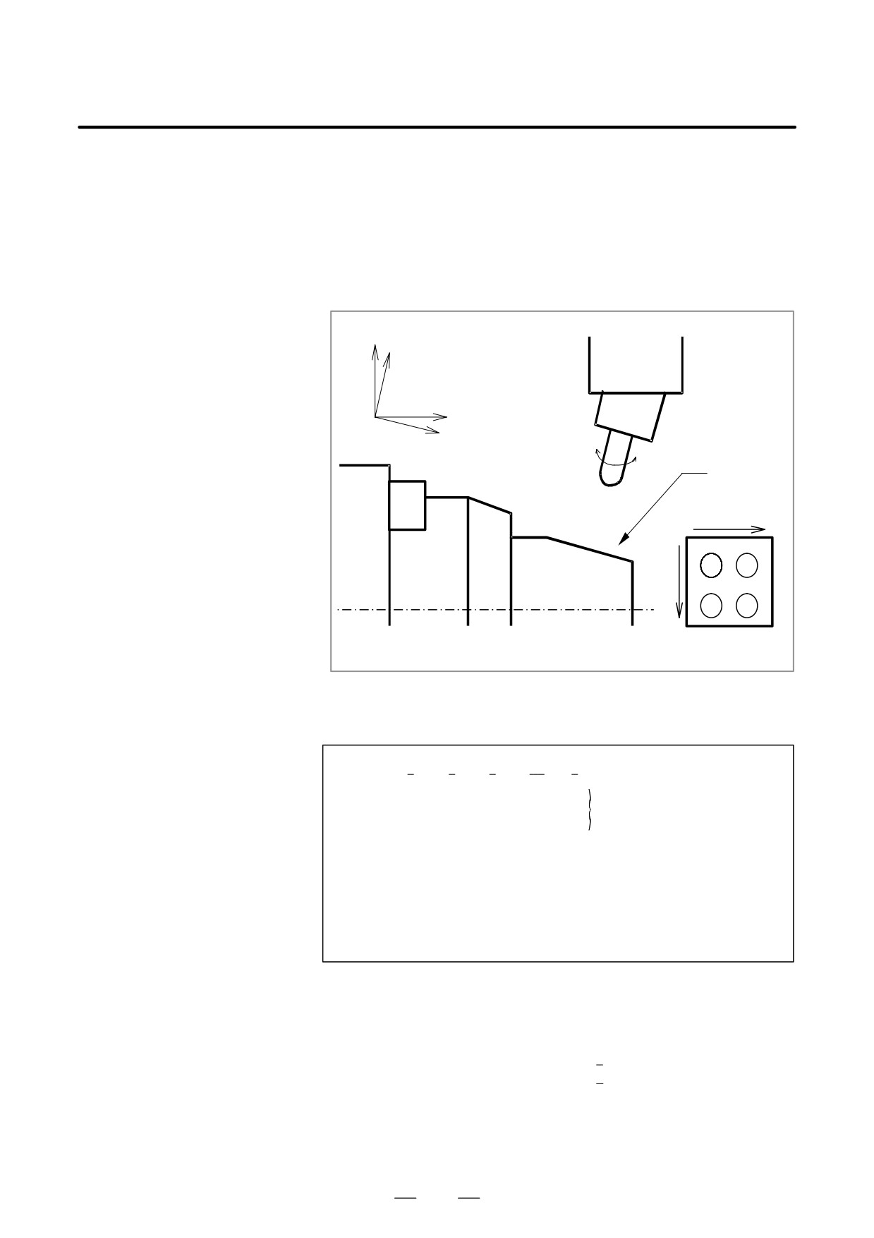
Coordinate conversion about an axis can be carried out if the center of
13.9
rotation, direction of the axis of rotation, and angular displacement are
THREE-
specified. This function is very useful for three-dimensional machining
DIMENSIONAL
such as B-axis machining. For example, if a program specifying
COORDINATE
machining on the ZX plane is converted by the three-dimensional
coordinate conversion function, the identical machining can be executed
CONVERSION
on a desired plane in three-dimensional space.
(G68.1, G69.1)
X
X*
Z
Z*
B
Surface to
be machined
Z
#1
#4
#2
#3
Y
Machining such as milling, pocketing, and
drilling is performed.
Format
G68.1 Xp x1 Yp y1 Zp z1 Ii1 J j1 K k1 Rα ; Starting three-dimensional
coordinate conversion
@
@
@
Three-dimensional coordi-
@
nate conversion mode
G69.1 ;
Canceling three-dimensional
coordinate conversion
Xp, Yp, Zp : Center of rotation (absolute coordinates) on the X, Y, and Z
axis or parallel axes
I, J, K :
Direction of the axis of rotation
R
:
Angular displacement
Explanations
D Command for
N1 G68.1 Xp x1 Yp y1 Zp z1 I i1 J j1 K k1 R α ;
three-dimensional
N2 G68.1 Xp x2 Yp y2 Zp z2 I i2 J j2 K k2 R β ;
coordinate conversion
N3
(program coordinate
:
system)
Nn G69.1 ;
Three-dimensional coordinate conversion can be executed twice.
211
13.
FUNCTIONS TO SIMPLIFY
PROGRAMMING
PROGRAMMING
B-63524EN/01
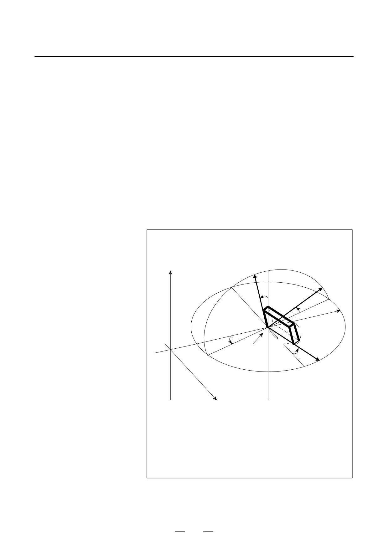
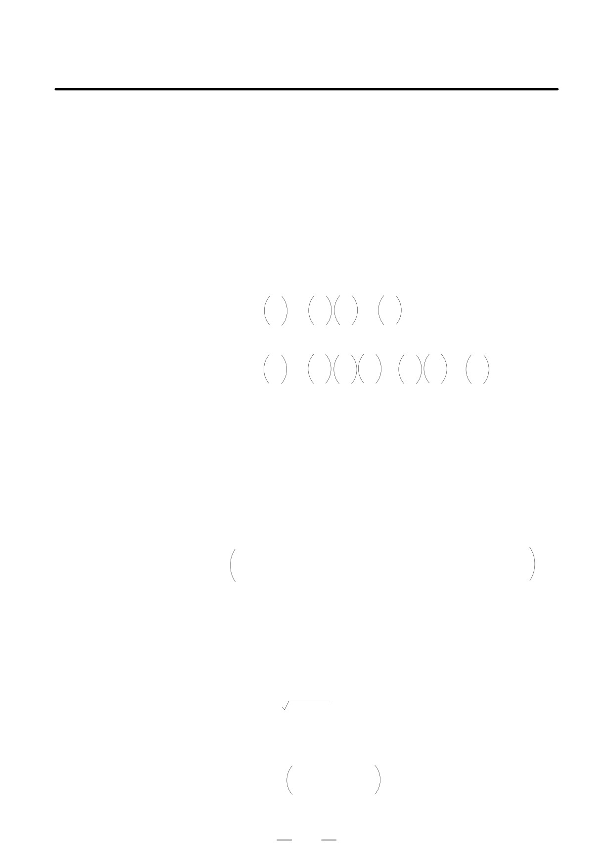
In the N1 block, specify the center, direction of the axis of rotation, and
angular displacement of the first rotation. When this block is executed,
the center of the original coordinate system is shifted to (x1, y1, z1), then
rotated around the vector (i1, j1, k1) by angular displacement α. The new
coordinate system is called X’Y’Z’. In the N2 block, specify the center,
direction of the axis of rotation, and angular displacement of the second
rotation. In the N2 block, specify coordinates and the angle with the
coordinate system formed after the N1 block in Xp, Yp, Zp, I, J, K, and
R. When the N2 block is executed, the X’Y’Z’ coordinate system is
shifted to (x2, y2, z2), then rotated around the vector (i2, j2, k2) by angular
displacement β . The newest coordinate system is called X’’Y’’Z’’. In the
subsequent N3 block, coordinates in the X’’Y’’Z’’ coordinate system are
specified with Xp, Yp, and Zp. The X’’Y’’Z’’ coordinate system is called
the program coordinate system.
If (Xp, Yp, Zp) is not specified in the N2 block, (Xp, Yp, Zp) in the N1
block is assumed to be the center of the second rotation (the N1 and N2
blocks have a common center of rotation). If the coordinate system is to
be rotated only once, the N2 block need not be specified.
Example) G68.1 Xx0 Yy0 Zz0 I0 J0 K1 Rα ;
G68.1 I1 J0 K0 Rβ ;
Z
Z’
Z"
Y"
β
Y’
β
P (x, y, z)
z
α
x
Y
y
O (x0, y0, z0)
α
X
X, Y, Z
:
Workpiece coordinate system
X’, Y’, Z’ :
Coordinate system formed after the first conversion
X”, Y”, Z”
:
Coordinate system formed after the second conversion
α:
Angular displacement of the first rotation
β :
Angular displacement of the second rotation
O (x0, y0, z0):
Center of rotation
P (x, y, z)
: Coordinates in the X’’Y’’Z’’ coordinate system (program
coordinate system)
212
13. FUNCTIONS TO SIMPLIFY
B-63524EN/01
PROGRAMMING
PROGRAMMING
D Format error
If one of the following format errors is detected, P/S alarm No. 5044 occurs:
1. When I, J, or K is not specified in a block with G68.1
(a parameter of coordinate system rotation is not specified)
2. When I, J, and K are all set to 0 in a block with G68.1
3. When R is not specified in a block with G68.1
D Center of rotation
Specify absolute coordinates with Xp, Yp, and Zp in the G68.1 block.
D Equation for
The following equation shows the general relationship between (x, y, z)
three-dimensional
in the program coordinate system and (X, Y, Z) in the original coordinate
coordinate conversion
system (workpiece coordinate system).
X
x
x1
Y
= M1
y1
y
+
Z
z
z1
When conversion is carried out twice, the relationship is expressed as follows:
X
x
x2
x1
Y
= M1
M2
M1
y2
y1
y
+
+
Z
z
z2
z1
X, Y, Z
: Coordinates in the original coordinate system
(workpiece coordinate system or machine coordinate system)
x, y, z : Programmed value
(coordinates in the program coordinate system)
x1, y1, z1
: Center of rotation of the first conversion
x2, y2, z2
: Center of rotation of the second conversion
(coordinates in the coordinate system formed after the
first conversion)
M1
: First conversion matrix
M2
: Second conversion matrix
M1 and M2 are conversion matrices determined by an angular displacement and
rotation axis. Generally, the matrices are expressed as shown below:
n12+(1-n12) cosθ
n1n2 (1-cosθ)-n3sinθ n1n3 (1-cosθ)+n2sinθ
n1 n2 (1-cosθ)+n3 sinθ
n22+(1-n22) cosθ
n2 n3 (1-cosθ)-n1 sinθ
n1 n3 (1-cosθ)-n2 sinθ n2 n3 (1-cosθ)+n1 sinθ n32+(1-n32) cosθ
i
n1
: Cosine of the angle made by the rotation axis and X-axis
p
j
n2
: Cosine of the angle made by the rotation axis and Y-axis
p
k
n3
: Cosine of the angle made by the rotation axis and Z-axis
p
θ: Angular displacement
Value p is obtained by the following:
p = i2+j2+k2
Conversion matrices for rotation on two-dimensional planes are shown below:
(1) Coordinate conversion on the XY plane
cosθ
-sinθ
0
M= sinθ cosθ
0
0
ă0
1
213
13. FUNCTIONS TO SIMPLIFY
PROGRAMMING
PROGRAMMING
B-63524EN/01
(2) Coordinate conversion on the ZY plane
1
0
0
M=
0
cosθ
-sinθ
0
sinθ
cosθ
(3) Coordinate conversion on the ZX plane
cosθ
0
sinθ
M=
0
1
0
–sinθ
0
cosθ
D Three basic axes and
Three-dimensional coordinate conversion can be applied to a desired
their parallel axes
combination of three axes selected out of the basic three axes (X, Y, Z) and
their parallel axes. The three-dimensional coordinate system subjected
to three-dimensional coordinate conversion is determined by axis
addresses specified in the G68.1 block. If Xp, Yp, or Zp is not specified,
X, Y, or Z of the basic three axes is assumed. However, if the basic three
axes are not specified in parameter 1022, P/S alarm No. 048 occurs.
In a single G68.1 block, both a basic axis and a parallel axis cannot be
specified. If this is attempted, P/S alarm No.047 occurs.
(Example)
When U-axis, V-axis, and W-axis are parallel to the X-axis, Y-axis, and
Z-axis respectively (when G code system B or C is used.)
G68.1 X_ I_ J_ K_ R_ ;
XYZ coordinate system
G68.1 U_V_ Z_ I_ J_ K_ R_ ; UVZ coordinate system
G68.1 W_ I_ J_ K_ R_ ;
XYW coordinate system
D Specifying the second
Three-dimensional coordinate conversion can be executed twice. The
conversion
center of rotation of the second conversion must be specified with the axis
addresses specified for the first conversion. If the axis addresses of the
second conversion are different from the axis addresses of the first
conversion, the different axis addresses are ignored. An attempt to
execute three-dimensional coordinate conversion three or more times
causes P/S alarm No.5043.
A positive angular displacement R indicates a clockwise rotation along
D Angular displacement R
the axis of rotation. Specify angular displacement R in 0.001 degrees
within the range of -360000 to 360000.
214
13. FUNCTIONS TO SIMPLIFY
B-63524EN/01
PROGRAMMING
PROGRAMMING
D G codes that can be
The following G codes can be specified in the three-dimensional
specified
coordinate conversion mode:
G00
Positioning
G01
Linear interpolation
G02
Circular interpolation (clockwise)
G03
Circular interpolation (counterclockwise)
G04
Dwell
G10
Data setting
G17
Plane selection (XY)
G18
Plane selection (ZX)
G19
Plane selection (YZ)
G28
Reference position return
G29
Return from the reference position
G30
Return to the second, third, or fourth reference position
G40
Canceling tool nose radius compensation
G41
Tool nose radius compensation to the left
G42
Tool nose radius compensation to the right
G53
Selecting the machine coordinate system
G65
Custom macro calling
G66
Continuous-state custom macro calling
G67
Canceling continuous-state custom macro calling
G80
Canceling a drilling cycle
G83 to G89
Drilling cycle
G90
Absolute mode (when G code system B or C is used.)
G91
Incremental mode (when G code system B or C is used.)
G94
Feed per minute (when G code system B or C is used.)
G95
Feed per rotation (when G code system B or C is used.)
G98
Canned cycle (return to the initial level) (when G code system B or
C is used.)
G99
Canned cycle (return to the level of point R) (when G code system B
or C is used.)
D Rapid traverse rate in
In three-dimensional coordinate conversion mode, rapid traverse rate in
drilling of a canned cycle
drilling by a canned cycle for drilling equals the cutting feedrate specified
for drilling
in parameter 5412. If the parameter is set to 0, the rapid traverse rate
equals the maximum cutting feedrate.
D Compensation functions
If tool nose radius compensation is specified with three-dimensional
(tool nose radius
coordinate conversion, compensation is performed first, followed by
compensation)
three-dimensional coordinate conversion.
D Relationship between
Three-dimensional and two-dimensional coordinate conversion use
three-dimensional and
identical G codes (G68.1 and G69.1). A G code specified with I, J, and
two-dimensional
K is processed as the command for three-dimensional coordinate
coordinate conversion
conversion. A G code not specified with I, J, and K is processed as the
(G68.1, G69.1)
command for two-dimensional coordinate conversion.
D Custom macro system
Coordinates on the workpiece coordinate system are assigned to system
variables
variables #5041 to #5048 (current position on each axis).
215
13. FUNCTIONS TO SIMPLIFY
PROGRAMMING
PROGRAMMING
B-63524EN/01
D Reset
If a reset occurs during three-dimensional coordinate conversion mode,
the mode is canceled and the continuous-state G code is changed to
G69.1.
The D3R bit (bit 2 of parameter 5400) determines whether just the G69.1
code is used to cancel the three-dimensional coordinate conversion mode
(G68.1). When this setting is selected, a CNC reset by a reset operation
or by an input signal from the PMC will not cancel the three-dimensional
coordinate conversion mode.
D Three-dimensional rigid
By specifying the rigid tapping command in three-dimensional
tapping
coordinate conversion mode, tapping can be executed in the direction of
the angle programmed by the three-dimensional coordinate conversion
command.
In three-dimensional coordinate conversion mode, ”Position Error Z”,
displayed on the spindle adjustment screen, is taken from the longitudinal
tapping axis after three-dimensional conversion.
Positioning in three-dimensional coordinate conversion mode must be
linear interpolation positioning (the LRP bit (bit 1 of parameter 1401) is
set to 1).
Three-dimensional rigid tapping cannot be executed for an axis under
simple synchronous control.
Limitations
D manual intervention
Three-dimensional coordinate conversion does not affect the degree of
manual handle interrupt.
D Positioning in the
Three-dimensional coordinate conversion does not affect positioning in
machine coordinate
the machine coordinate system (e.g. specified with G28, G30, or G53).
system
D Specifying rapid traverse
Specify linear rapid traverse when three-dimensional coordinate
conversion is executed. (Set the LRP bit, bit 1 of parameter No.1401, to
1.)
D Block with G68.1 or
In a block with G68.1 or G69.1, other G codes must not be specified.
G69.1
G68.1 must be specified with I, J, and K.
D Mirror image
External mirror image (mirror image by the mirror image signal or
setting) cannot be specified.
D Position display and
To display the absolute position when three-dimensional coordinate
compensation
conversion is executed, set bits 4 to 7 of parameter DRL, DRC, DAL, and
DAC No.3104 to 0.
D Three-dimensional
Canned cycles G41 or G42 must be nested between G68.1 and G69.1.
coordinate conversion
(Example)
and other
G68.1 X100. Y100. Z100. I0. J0. K1. R45. ;
continuous-state
commands
G41 X_ Z_ I_ K_ ;
L
G40 ;
L
G69.1 ;
L
216
13. FUNCTIONS TO SIMPLIFY
B-63524EN/01
PROGRAMMING
PROGRAMMING
D Relationship between
When using a tool offset command, nest the tool offset command within
three-dimensional
the three-dimensional coordinate conversion mode.
coordinate conversion
(Example)
and tool offset
G68.1 X100. Y100. Z100. I0. J0. K1. R45. ;
L
T0101 ;
L
T0100 ;
L
G69.1 ;
D PMC axis control
In the three-dimensional coordinate conversion mode, PMC axis control
cannot be performed for the three axes related to the conversion (P/S
alarm).
D Manual operation
When manual feeding is performed during a three-dimensional
coordinate conversion, the tangent velocity in the coordinate system after
conversion (program coordinate system) equals the lowest feedrate of
those on the selected axes.
D Workpiece coordinate
Avoid changing the workpiece coordinate system in the three-dimensional
system
coordinate conversion mode.
D Manual reference
Avoid making a manual reference position return in the three-dimensional
position return
coordinate conversion mode.
D Cs contour axis
When specifying the Cs contour axis and rapid traverse at the same time
in the three-dimensional coordinate conversion mode, make a reference
position return on the Cs contour axis in advance. If a reference position
return is made in the first rapid traverse after the Cs contour axis is
selected (bit NRF (bit 1 of parameter 3700) is set to 0), avoid specifying
the reference position return command in the three-dimensional
coordinate conversion mode.
217
13. FUNCTIONS TO SIMPLIFY
PROGRAMMING
PROGRAMMING
B-63524EN/01
Examples
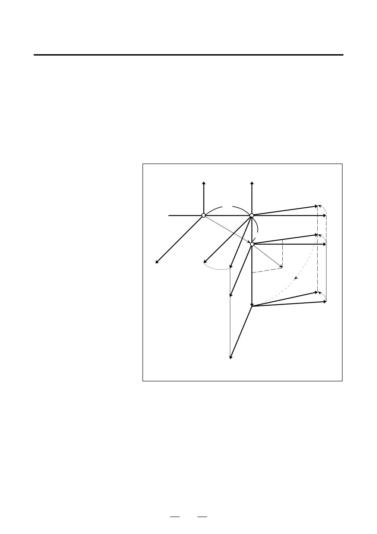
An example of G code system B is described below.
N1 G90 X0 Y0 Z0 ;
Carries out positioning to zero point H.
N2 G68.1 X10. Y0 Z0 I0 J1 K0 R30. ;
Forms new coordinate system X’Y’Z’.
N3 G68.1 X0 Y-10. Z0 I0 J0 K1 R-90. ; Forms other coordinate system X’’Y’’Z’’.
The origin agrees with
(0,
-10,
0) in
coordinate system X’Y’Z.
N4 G90 X0 Y0 Z0 ;
Carries out positioning to zero point H’’ on
coordinate system X’’Y’’Z’’.
N5 X10. Y10. Z0 ;
Carries out positioning to (10, 10, 0) on
coordinate system X’’Y’’Z’’.
Y
Y’
X’
10
30°
H
H’
X
N4
Y”
-10
H”
N5
Z
Z’
(10, 10, 0)
30°
Z”
X”
218