FANUC Series Series 16i-TB, Series 18i-TB, Series 160i-TB, Series 180i-TB. OPERATOR’S MANUAL - page 7
13. FUNCTIONS TO SIMPLIFY
B-63524EN/01
PROGRAMMING
PROGRAMMING
WARNING
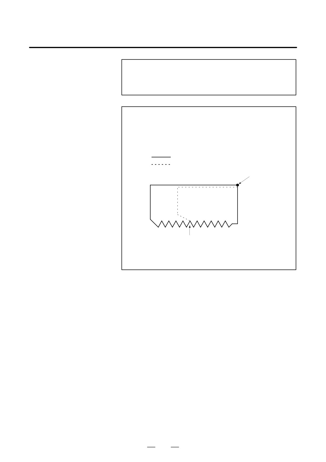
Notes on this thread cutting are the same as in thread
cutting in G32. However, a stop by feed hold is as follows;
Stop after completion of path 3 of thread cutting cycle.
CAUTION
The tool retreats while chamfering and returns to the start
point on the X axis then the Z axis, as soon as the feed hold
status is entered during thread cutting (motion 2) when the
“Thread Cutting Cycle retract” option is used.
Ordinary cycle
Motion at feed hold
Stop point
Rapid traverse
Feed hold is effected here.
Another feed hold cannot be made during retreat. The
chamfered amount is the same as that at the end point.
159
13. FUNCTIONS TO SIMPLIFY
PROGRAMMING
PROGRAMMING
B-63524EN/01
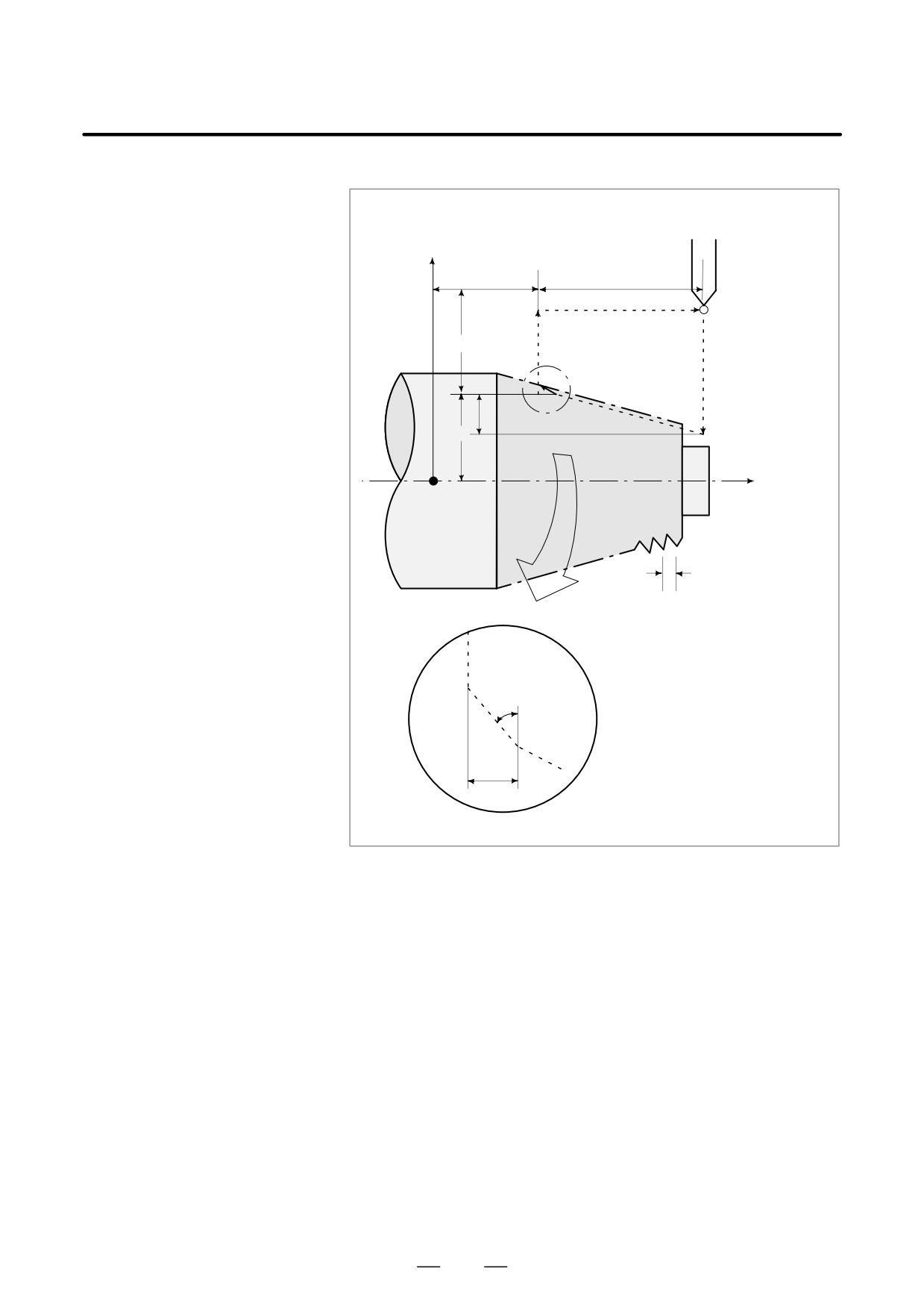
D Taper thread cutting
cycle
G92X(U)__ Z(W)__ R__ F__ ; Lead (L) is specified.
X axis
Z
W
4(R)
(R) 0Rapid traverse
U/2
(F) 0Specified by
3(R)
1(R)
F code
2(F)
R
X/2
Z axis
L
(The chamfered angle in the left figure
is 45 degrees or less because of the
delay in the servo system.
Approx. 45°
r
Detailed chamfered thread
Fig. 13.1.2 (b) Taper thread cutting cycle
160
13. FUNCTIONS TO SIMPLIFY
B-63524EN/01
PROGRAMMING
PROGRAMMING
13.1.3
End Face Turning
Cycle (G94)
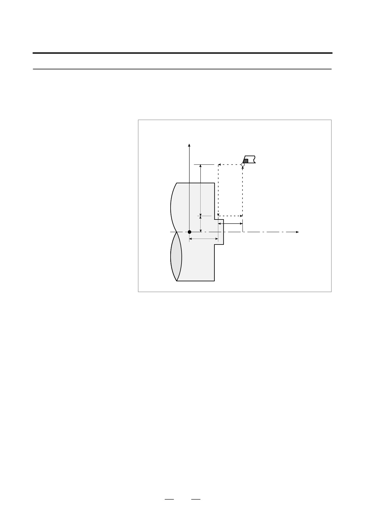
D Face cutting cycle
G94X(U)__ Z(W)__ F__ ;
X axis
(R)……Rapid traverse
(F)……Specified by F code
1(R)
2(F)
4(R)
U/2
3(F)
X/2
X/2
0
W
Z axis
Z
Fig. 13.1.3 (a) Face Cutting Cycle
In incremental programming, the sign of numbers following addresses U
and W depends on the direction of paths 1 and 2. That is, if the direction
of the path is in the negative direction of the Z axis, the value of W is
negative.
In single block mode, operations 1, 2, 3, and 4 are performed by pressing
the cycle start button once.
161
13. FUNCTIONS TO SIMPLIFY
PROGRAMMING
PROGRAMMING
B-63524EN/01
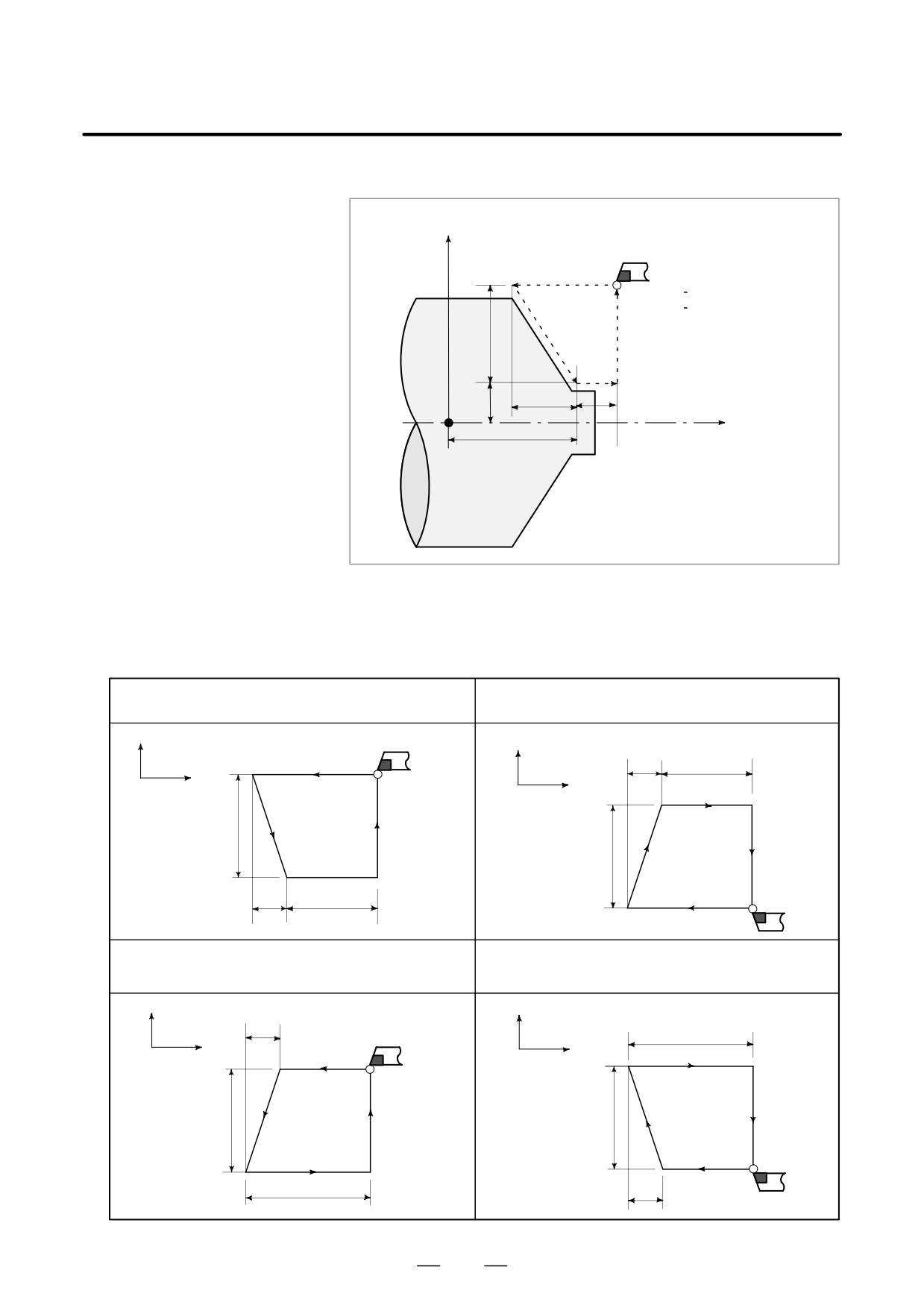
D Taper face cutting cycle
X axis
1(R)
(R) Rapid traverse
(F) Specified by F code
2(F)
4(R)
U/2
3(F)
X/2
R
W
Z axis
Z
Fig. 13.1.3 (b)
D Signs of numbers
In incremental programming, the relationship between the signs of the
specified in the taper
numbers following address U, W, and R, and the tool paths are as follows:
cutting cycle
1. U < 0, W < 0, R < 0
2. U > 0, W < 0, R < 0
X
X
1(R)
R
W
Z
Z
3(F)
U/2
2(F)
4(R)
U/2
2(F)
4(R)
3(F)
1(R)
R
W
3. U < 0, W < 0, R > 0
4. U > 0, W < 0, R<0
at R x
W
at R x W
X
X
R
W
Z
Z
3(F)
1(R)
U/2
2(F)
4(R)
U/2
2(F)
4(R)
3(F)
1(R)
W
R
162
13. FUNCTIONS TO SIMPLIFY
B-63524EN/01
PROGRAMMING
PROGRAMMING
NOTE
1
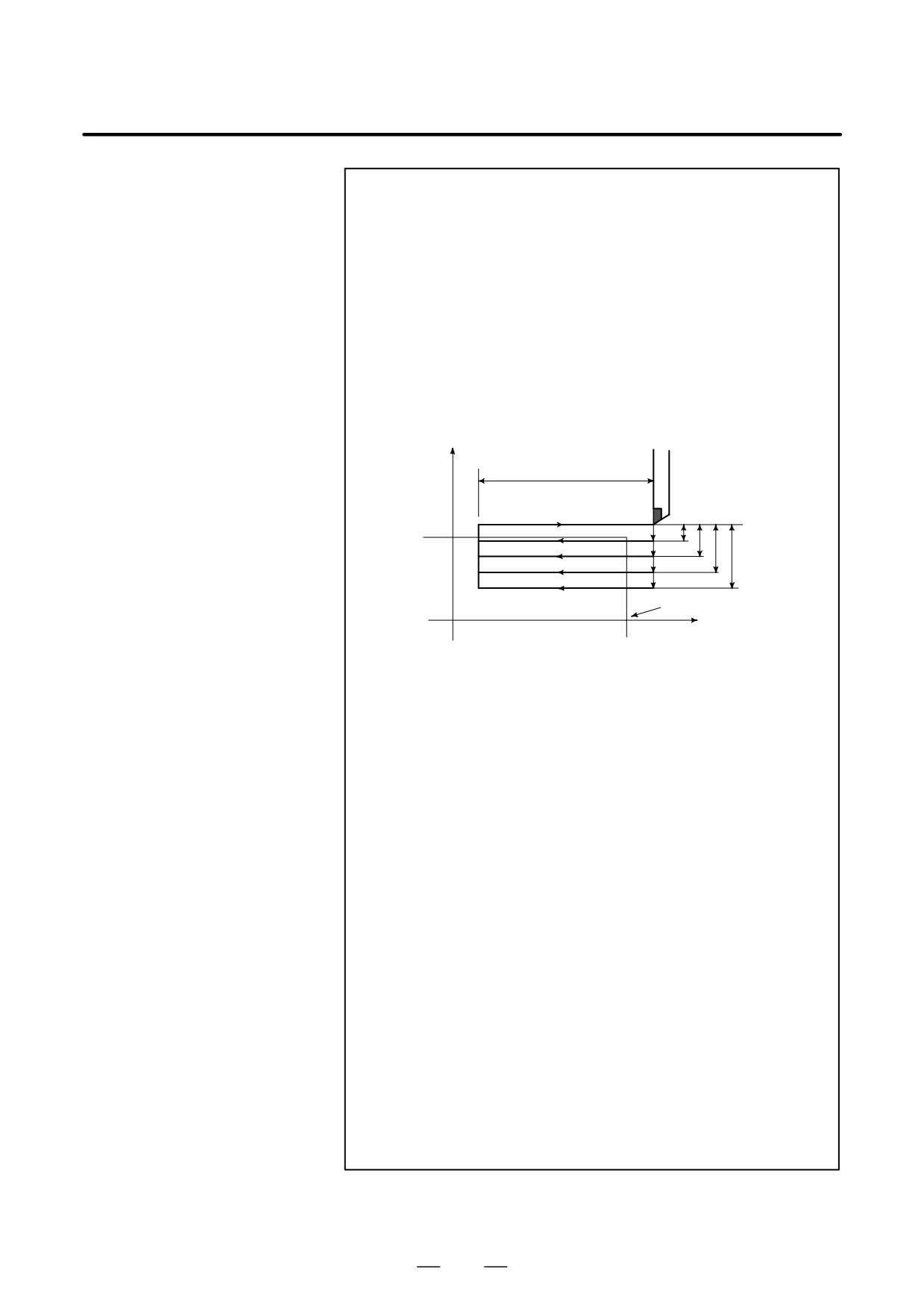
Since data values of X (U), Z (W) and R during canned cycle are
modal, if X (U), Z (W), or R is not newly commanded, the previously
specified data is effective. Thus, when the Z axis movement
amount does not vary as in the example below, a canned cycle can
be repeated only by specifying the movement commands for the
X-axis.
However, these data are cleared, if a one-shot G code expect for
G04 (dwell) or a G code in the group 01 except for G90, G92, G94
is commanded.
(Example)
X axis
66
4
8
12
16
Workpiece
0
Z axis
The cycle in the above figure is executed by the following program.
N030
G90 U-8.0 W-66.0 F0.4 ;
N031
U-16.0 ;
N032
U-24.0 ;
N033
U-32.0 ;
2
The following two applications can be performed.
(1) If an EOB or zero movement commands are specified for the
block following that specified with a canned cycle, the same
canned cycle is repeated.
(2) If the M, S, T function is commanded during the canned cycle
mode, both the canned cycle and M, S, or T function can be
performed simultaneously. If this is inconvenient, cancel the
canned cycle once as in the program examples below (specify
G00 or G01) and execute the M, S, or T command. After the
execution of M, S, or T terminates, command the canned cycle
again.
(Example)
N003 T0101 ;
:
:
N010
G90 X20.0 Z10.0 F0.2 ;
N011
G00 T0202 ;
N012
G90 X20.5 Z10.0 ;
163
13. FUNCTIONS TO SIMPLIFY
PROGRAMMING
PROGRAMMING
B-63524EN/01
13.1.4
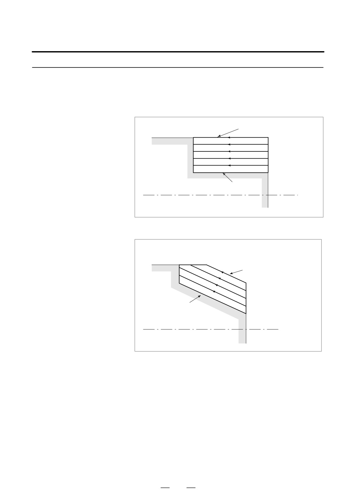
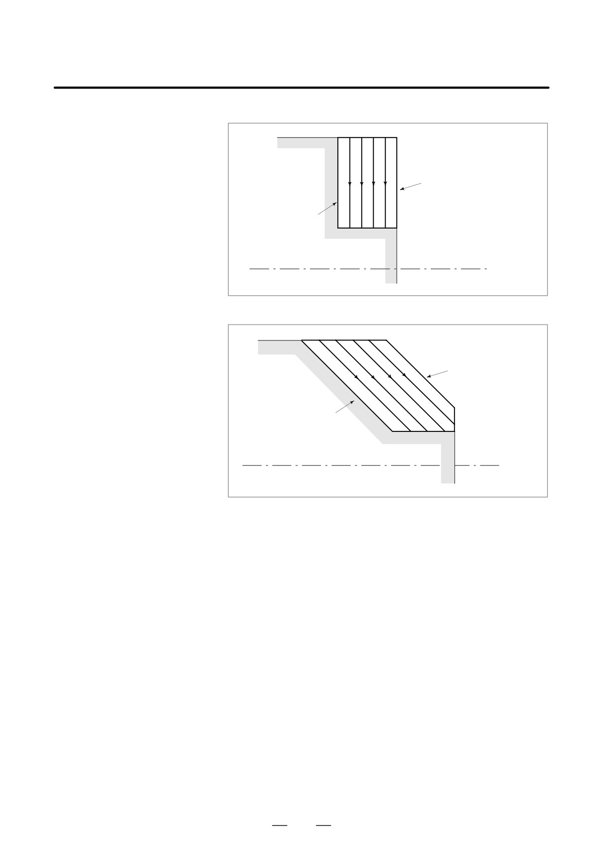
An appropriate canned cycle is selected according to the shape of the
material and the shape of the product.
How to Use Canned
Cycles (G90, G92, G94)
D Straight cutting cycle
(G90)
Shape of material
Shape of product
D Taper cutting cycle (G90)
Shape of material
Shape of product
164
13. FUNCTIONS TO SIMPLIFY
B-63524EN/01
PROGRAMMING
PROGRAMMING
D Face cutting cycle (G94)
Shape of material
Shape of product
D Face taper cutting cycle
(G94)
Shape of material
Shape of product
165
13. FUNCTIONS TO SIMPLIFY
PROGRAMMING
PROGRAMMING
B-63524EN/01
This option canned cycles to make CNC programming easy. For instance,
13.2
the data of the finish work shape describes the tool path for rough
MULTIPLE
machining. And also, a canned cycles for the thread cutting is available.
REPETITIVE CYCLE
(G70-G76)
13.2.1
There are two types of stock removals in turning : Type I and II.
Stock Removal in
Turning (G71)
D Type I
If a finished shape of A to A′ to B is given by a program as in the figure
below, the specified area is removed by ∆d (depth of cut), with finishing
allowance ∆u/2 and ∆w left.
C
B
(R)
A
∆d
(R)
(F)
45,
e
(F)
Program command
(F) : Cutting feed
∆u/2
(R) : Rapid traverse
∆w
A′
G71 U (∆d) R (e) ;
G71 P (ns) Q (nf) U (∆u) W (∆w) F (f ) S (s ) T (t)
N (ns)⋅⋅⋅⋅⋅⋅⋅⋅⋅⋅⋅
⋅⋅⋅⋅⋅⋅⋅⋅⋅⋅⋅⋅⋅⋅⋅⋅
F____
The move command between A and B is
S____
specified in the blocks from sequence
T____
number ns to nf.
N (nf)⋅⋅⋅⋅⋅⋅⋅⋅⋅⋅⋅;
∆d
: Depth of cut (radius designation)
Designate without sign. The cutting direction depends on the direction AA′. This
designation is modal and is not changed until the other value is designated. Also
this value can be specified by the parameter (No. 5132), and the parameter is
changed by the program command.
e
: Escaping amount
This designation is modal and is not changed until the other value is designated.
Also this value can be specified by the parameter (No. 5133), and the parameter
is changed by the program command.
ns
: Sequence number of the first block for the program of finishing shape.
nf
: Sequence number of the last block for the program of finishing shape.
∆u
: Distance and direction of finishing allowance in X direction (diameter / radius
designation).
∆w : Distance and direction of finishing allowance in Z direction.
f,s,t
: Any F , S, or T function contained in blocks ns to nf in the cycle is ignored, and the
F, S, or T function in this G71 block is effective.
Fig. 13.2.1 (a) Cutting Path in Stock Removal in Turning (Type I)
166
13. FUNCTIONS TO SIMPLIFY
B-63524EN/01
PROGRAMMING
PROGRAMMING
NOTE
1
While both ∆d and ∆u, are specified by address U, the
meanings of them are determined by the presence of
addresses P and Q.
2
The cycle machining is performed by G71 command with P
and Q specification.
F, S, and T functions which are specified in the move
command between points A and B are ineffective and those
specified in G71 block or the previous block are effective.
When an option of constant surface speed control is
selected, G96 or G97 command specified in the move
command between points A and B are ineffective, and that
specified in G71 block or the previous block is effective.
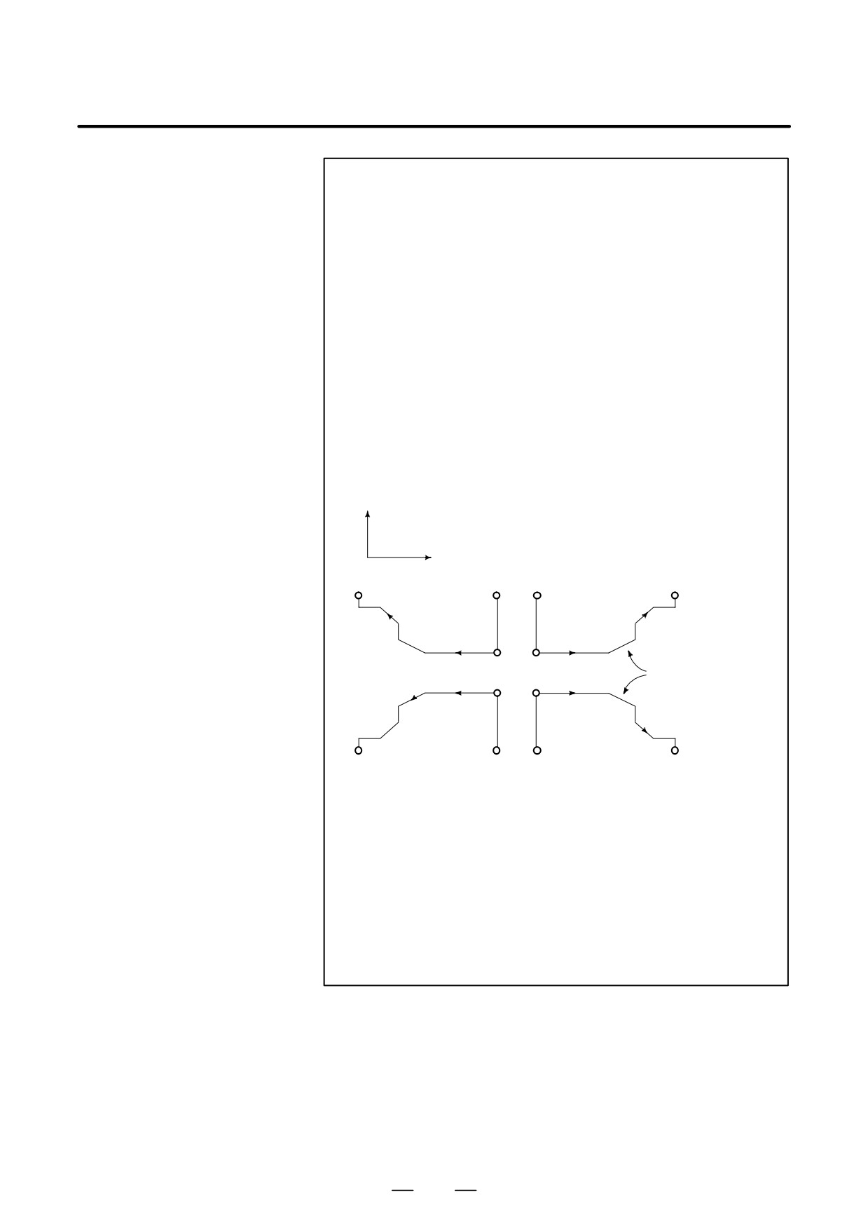
The following four cutting patterns are considered. All of
these cutting cycles are made paralleled to Z axis and the
sign of ∆u and ∆w are as follows:
+X
+Z
B
A
A
U(+)…W(+)
U(+)…W(-)
A′
A′
Both linear and cir-
A′ A′
cular interpolation
are possible
U(-)…W(+)
U(-)…W(-)
A
A
The tool path between A and A′ is specified in the block with
sequence number “ns” including G00 or G01, and in this
block, a move command in the Z axis cannot be specified.
The tool path between A′ and B must be steadily increasing
or decreasing pattern in both X and Z axis. When the tool
path between A and A′ is programmed by G00/G01, cutting
along AA′ is performed in G00/G01 mode respectively.
3
The subprogram cannot be called from the block between
sequence number “ns” and “nf”.
167
13. FUNCTIONS TO SIMPLIFY
PROGRAMMING
PROGRAMMING
B-63524EN/01
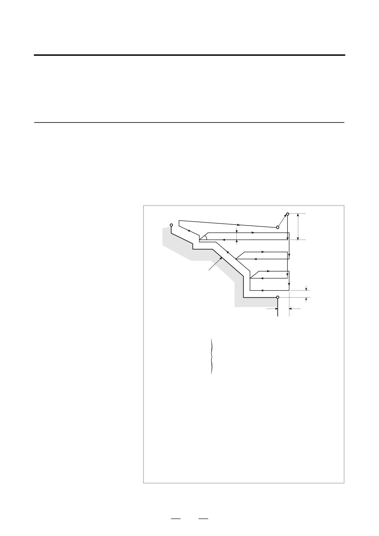
D Type II
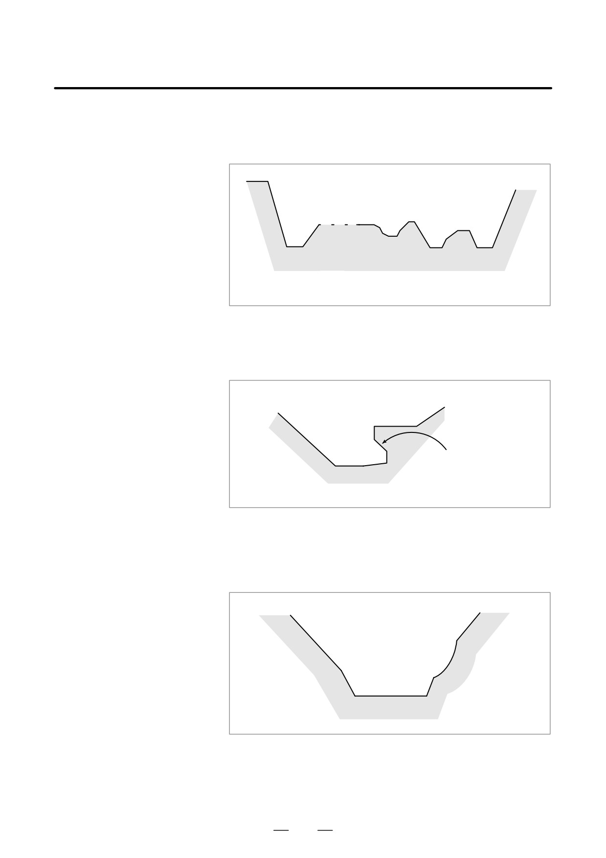
Type II differs from type I in the following : The profile need not show
monotone increase or monotone decrease along the X axis, and it may
have up to 10 concaves (pockets).
10
3
2
1
Fig. 13.2.1 (b) Number of Pockets in Stock Removal in Turning (Type II)
Note that, however, the profile must have monotone decrease or increase
along the Z axis. The following profile cannot be machined:
Monotone change is not
observed along the Z axis
Fig. 13.2.1 (c) Figure Which Cannot Be Machined in Stock Removal in
Turning (Type II)
The first cut portion need not be vertical ; any profile is permitted if
monotone change is shown along the Z axis.
Fig. 13.2.1 (d) Figure Which Can Be Machined (Monotonic change) in
Stock Removal in Turning (Type II)
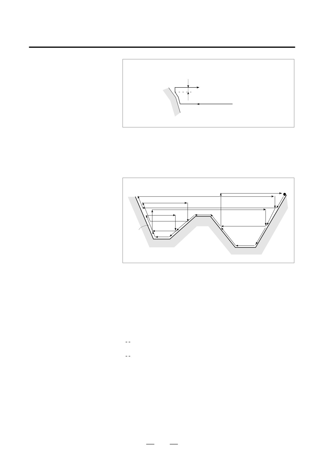
After turning, a clearance is provided by cutting along the workpiece
profile.
168
13. FUNCTIONS TO SIMPLIFY
B-63524EN/01
PROGRAMMING
PROGRAMMING
e (set by a parameter)
Fig. 13.2.1 (e) Chamfering in Stock Removal in Turning (Type II)
The clearance e (specified in R) to be provided after cutting can also be
set in parameter No. 5133.
A sample cutting path is given below:
30
4
3
13
5
1
29
2
12
18
14
9
24
10
6
23
8
25
11
19
15
7
16
17
22
20
26
21
28
27
Fig. 13.2.1 (f) Cutting Path in Stock Removal in Facing
The offset of the tool tip radius is not added to finishing allowances
∆u and ∆w. In turning, the offset of the tool tip radius is assumed to be
zero.
W=0 must be specified ; otherwise, the tool tip may cut into one wall side.
For the first block of a repetitive portion, two axes X (U) and Z (W) must
be specified. When Z motion is not performed, W0 is also specified.
D Distinction between type
When only one axis is specified in the first block of a repetitive portion
I and type II
Type I
When two axes are specified in the first block of a repetitive portion
Type II
When the first block does not include Z motion and type IIis to be used,
W0 must be specified.
(Example)
TYPE I
TYPE II
G71 V10.0 R5.0 ;
G71 V10.0 R5.0 ;
G71 P100 Q200
; G71 P100 Q200
;
N100X (U)___;
N100X (U)___ Z(W)___;
:
:
:
:
N200
;
N200
;
169
13. FUNCTIONS TO SIMPLIFY
PROGRAMMING
PROGRAMMING
B-63524EN/01
13.2.2
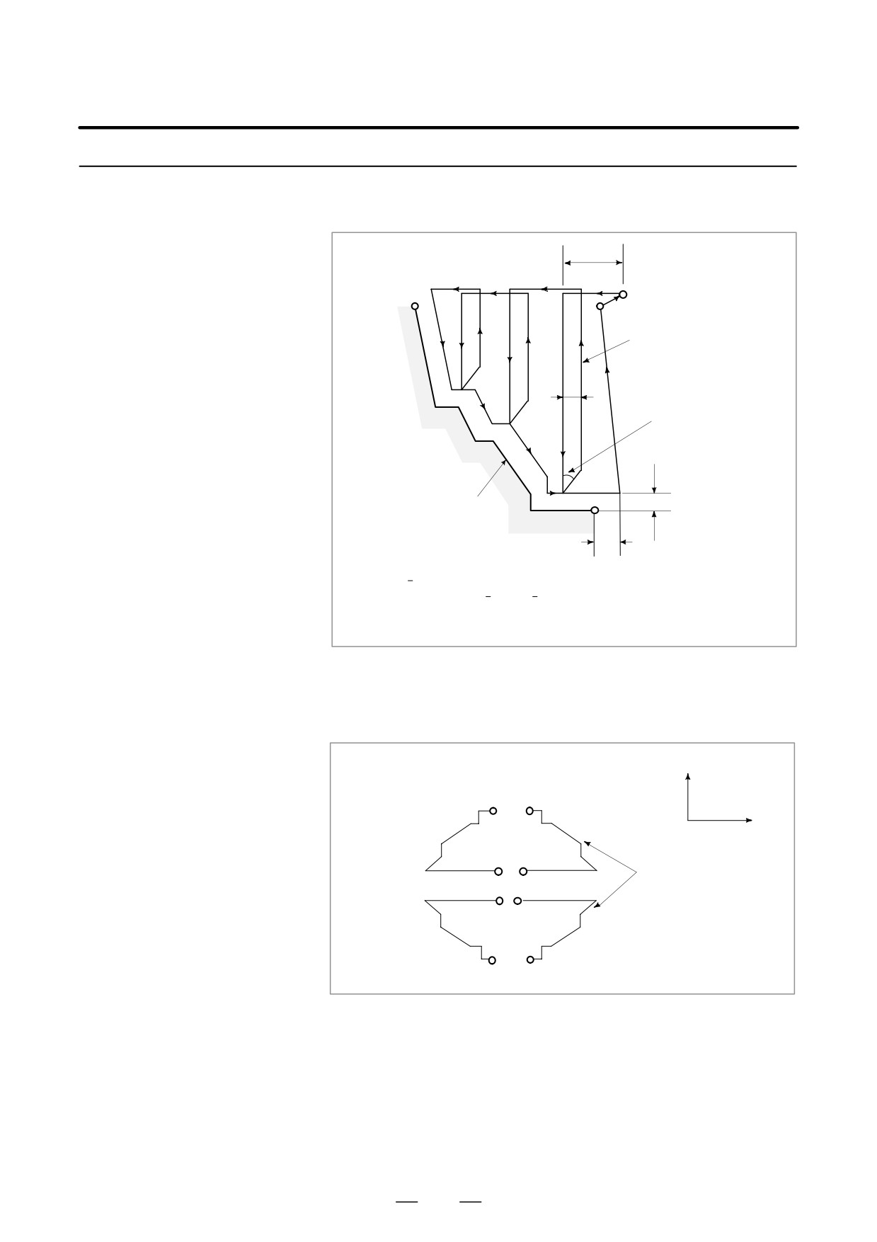
As shown in the figure below, this cycle is the same as G71 except that
cutting is made by a operation parallel to X axis.
Stock Removal in
Facing (G72)
∆d
C
A′
A
Tool path
(F)
(R)
e
(R)
45°
(F)
Program command
∆u/2
B
∆w
G72 W(∆d) R(e) ;
G72 P(ns) Q(nf) U(∆u) W(∆w) F(f) S(s) T(t) ;
The meanings of ∆d, e, ns, nf, ∆u,∆w, f, s, and t are the same as
those in G71.
Fig. 13.2.2 (a) Cutting Path in Stock Removal in Facing
D Signs of specified
The following four cutting patterns are considered. All of these cutting
numbers
cycles are made parallel to X axis and the sign of ∆u and ∆w are as follows:
+X
B
B
+Z
U(-)…W(+)…
U(-)…W(-)…
Both linear and circular
A′
A
A
A′
interpolation are possible
A
A
A′
A′
U(+)…W(+)…
U(+)…W(-)…
B B
Fig. 13.2.2 (b)
Signs of Numbers Specified with U and W in Stock Removal in Facing
The tool path between A and A′ is specified in the block with sequence
number “ns” including G00 or G01, and in this block, a move command
in the X axis cannot be specified. The tool path between A′ and B must
be steadily increasing and decreasing pattern in both X and Z axes.
Whether the cutting along AA′ is G00 or G01 mode is determined by the
command between A and A′, as described in item 13.2.1.
170
13. FUNCTIONS TO SIMPLIFY
B-63524EN/01
PROGRAMMING
PROGRAMMING
13.2.3
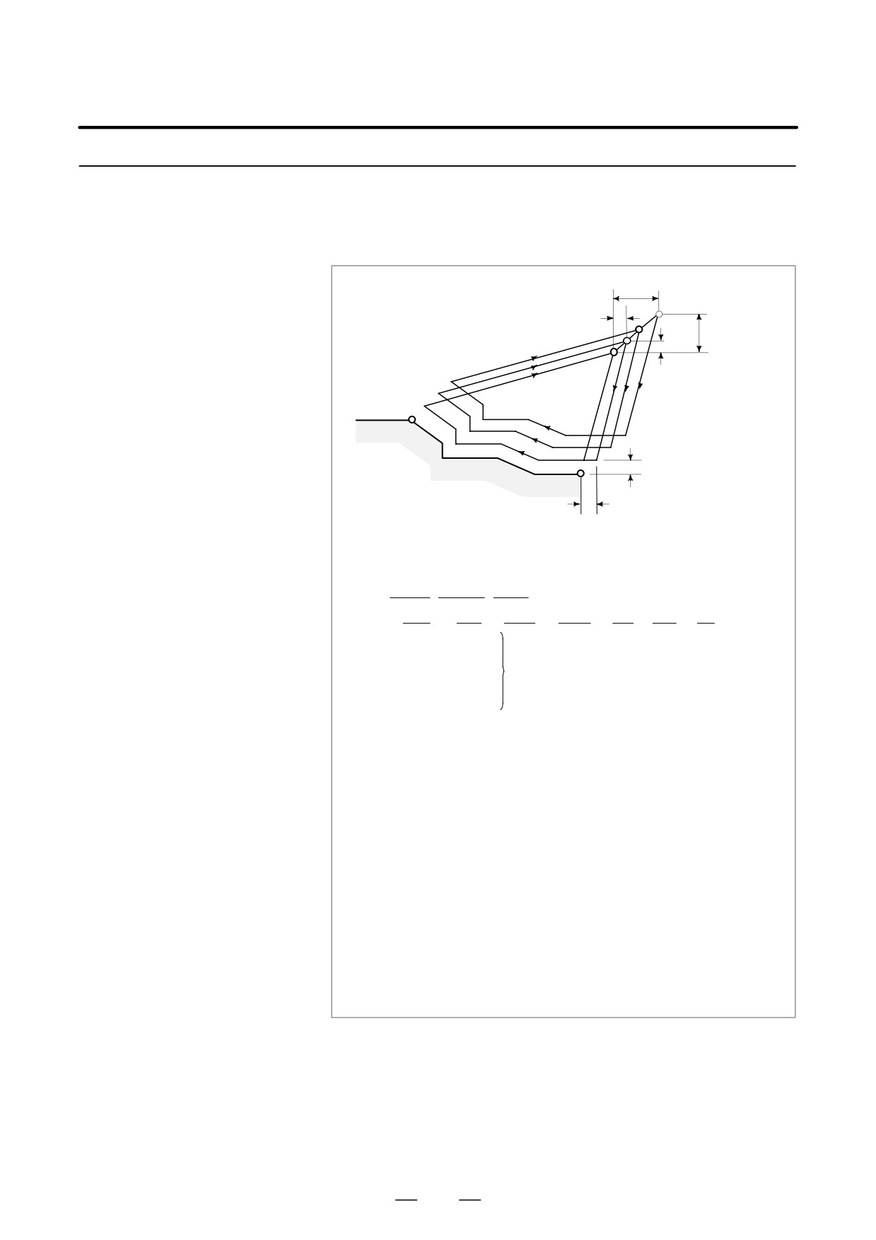
This function permits cutting a fixed pattern repeatedly, with a pattern
being displaced bit by bit. By this cutting cycle, it is possible to efficiently
Pattern Repeating
cut work whose rough shape has already been made by a rough
(G73)
machining, forging or casting method, etc.
∆k+∆w
D
∆w
∆i+∆u/2
C
∆u/2
A
(R)
B
∆u/2
A′
∆w
The pattern commanded in the program should be as follows.
A→A′→B
G73 U (ni) W (nk) R (d) ;
G73 P (ns) Q (nf) U (nu) W (nw) F (f ) S (s ) T (t) ;
N (ns)⋅⋅⋅⋅⋅⋅⋅⋅⋅⋅⋅
⋅⋅⋅⋅⋅⋅⋅⋅⋅⋅⋅⋅⋅⋅⋅⋅
The move command between A and B is
F____
specified in the blocks from sequence
S____
number ns to nf.
T____
N (nf)⋅⋅⋅⋅⋅⋅⋅⋅⋅⋅⋅;
∆i
: Distance and direction of relief in the X axis direction (Radius designation).
This designation is modal and is not changed until the other value is designated.
Also this value can be specified by the parameter No. 5135, and the parameter
is changed by the program command.
∆k
: Distance and direction of relief in the Z axis direction.
This designation is modal and is not changed until the other value is designated.
Also this value can be specified by the parameter No. 5136, and the parameter
is changed by the program command.
d
: The number of division
This value is the same as the repetitive count for rough cutting. This designation
is modal and is not changed until the other value is designated. Also, this value
can be specified by the parameter No. 5137, and the parameter is changed by
the program command.
ns
: Sequence number of the first block for the program of finishing shape.
nf
: Sequence number of the last block for the program of finishing shape.
nu : Distance and direction of finishing allowance in X direction (diameter/radius
designation)
nw : Distance and direction of finishing allowance in Z direction
f,s,t
: Any F, S, and T function contained in the blocks between sequence number “ns”
and “nf” are ignored, and the F, S, and T functions in this G73 block are effective.
Fig. 13.2.3 Cutting path in Pattern Repeating
171
13. FUNCTIONS TO SIMPLIFY
PROGRAMMING
PROGRAMMING
B-63524EN/01
NOTE
1
While the values ∆i and ∆k, or ∆u and ∆w are specified by
address U and W respectively, the meanings of them are
determined by the presence of addresses P and Q in G73
block. When P and Q are not specified in a same block,
addresses U and W indicates ∆i and ∆k respectively. When
P and Q are specified in a same block, addreses U and W
indicates ∆u and ∆w respectively.
2
The cycle machining is performed by G73 command with P
and Q specification.
The four cutting patterns are considered. Take care of the
sign of ∆u, ∆w, ∆k, and ∆i.
When the machining cycle is terminated, the tool returns to
point A.
13.2.4
After rough cutting by G71, G72 or G73, the following command permits
finishing.
Finishing Cycle (G70)
Format
G70P (ns) Q (nf) ;
(ns) : Sequence number of the first block for the program of
finishing shape.
(nf) : Sequence number of the last block for the program of
finishing shape.
NOTE
1
F, S, and T functions specified in the block G71, G72, G73
are not effective but those specified between sequence
numbers “ns” and “nf” are effective in G70.
2
When the cycle machining by G70 is terminated, the tool is
returned to the start point and the next block is read.
3
In blocks between “ns” and “nf” referred in G70 through
G73, the subprogram cannot be called.
172
13. FUNCTIONS TO SIMPLIFY
B-63524EN/01
PROGRAMMING
PROGRAMMING
Examples
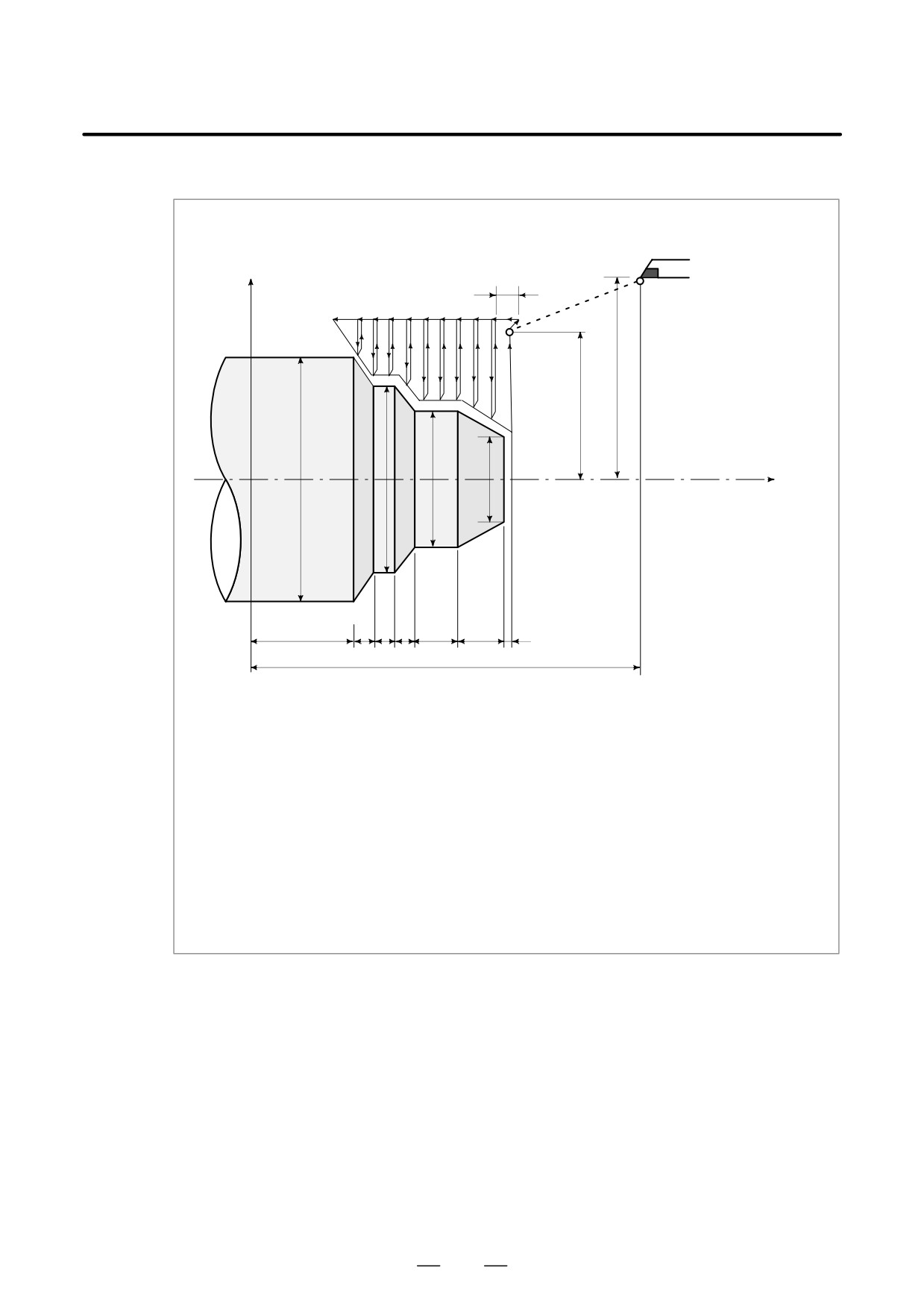
Stock Removal In Facing (G72)
X axis
7
Start point
88
110
Z axis
φ160
φ120
φ80
φ40
Å
ÅÅÅ
ÅÅÅ
ÅÅÅ
ÅÅ
Å
40
10
10 10
20
20
2
190
(Diameter designation, metric input)
N010 G50 X220.0 Z190.0 ;
N011 G00 X176.0 Z132.0 ;
N012 G72 W7.0 R1.0 ;
N013 G72 P014 Q019 U4.0 W2.0 F0.3 S550 ;
N014 G00 Z58.0 S700 ;
N015 G01 X120.0 W12.0 F0.15 ;
N016
W10.0 ;
N017
X80.0 W10.0 ;
N018
W20.0 ;
N019
X36.0 W22.0 ;
N020 G70 P014 Q019 ;
173
13. FUNCTIONS TO SIMPLIFY
PROGRAMMING
PROGRAMMING
B-63524EN/01
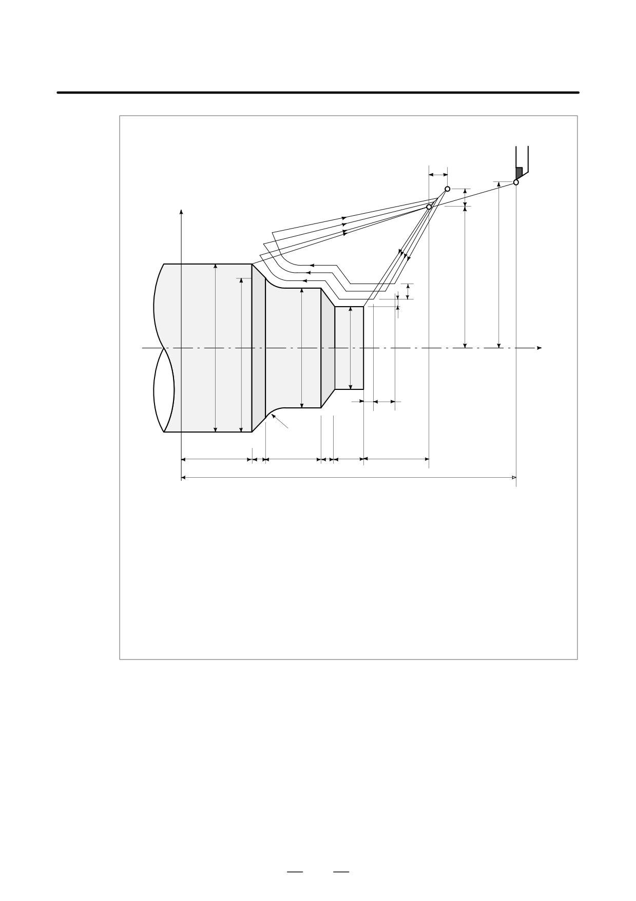
Pattern Repeating (G73)
16
B
X axis
16
110
130
14
2
Z axis
0
φ180
φ160
φ120
φ80
ÅÅ
ÅÅ
ÅÅ
2
14
ÅÅ
ÅÅ
20
ÅÅ
220
(Diameter designation, metric input)
N010 G50 X260.0 Z220.0 ;
N011 G00 X220.0 Z160.0 ;
N012 G73 U14.0 W14.0 R3 ;
N013 G73 P014 Q019 U4.0 W2.0 F0.3 S0180 ;
N014 G00 X80.0 W-40.0 ;
N015 G01 W-20.0 F0.15 S0600 ;
N017 W-20.0 S0400 ;
N018 G02 X160.0 W-20.0 R20.0 ;
N019 G01 X180.0 W-10.0 S0280 ;
N020 G70 P014 Q019 ;
174
13. FUNCTIONS TO SIMPLIFY
B-63524EN/01
PROGRAMMING
PROGRAMMING
13.2.5
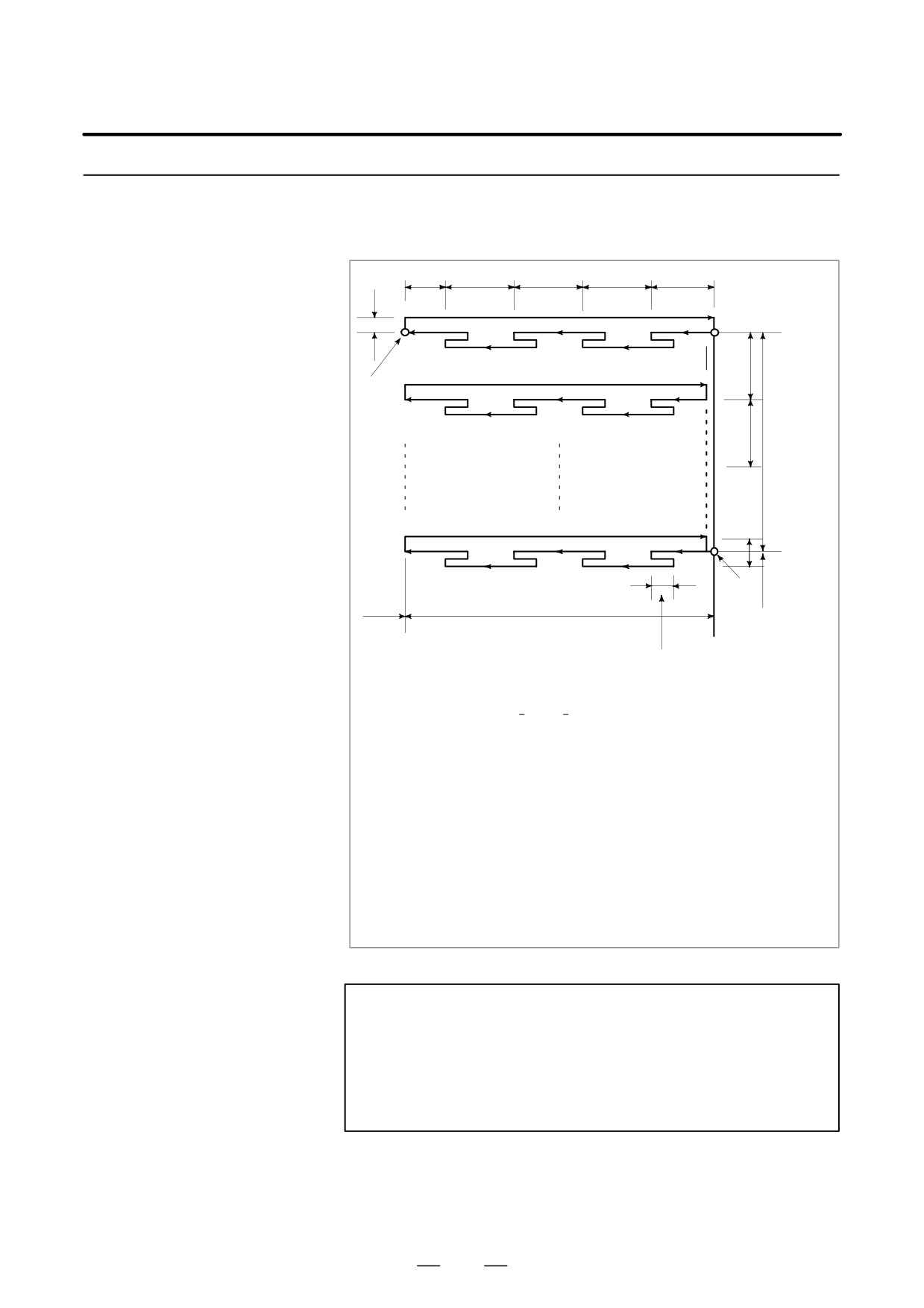
The following program generates the cutting path shown in Fig. 13.2.5.
Chip breaking is possible in this cycle as shown below. If X (U) and Pare
End Face Peck Drilling
omitted, operation only in the Z axis results, to be used for drilling.
Cycle (G74)
Dk′
Dk
Dk
Dk
Dk
Dd
A
[0<Dk′xDk]
Di
C
(R)
(R)
(R)
(R)
(R)
(R)
(F)
U/2
(F)
(F)
(F)
(F)
Di
Di′
X
B
[0<Di′xDi]
W
Z
e
G74R (e) ;
G74X(U)_ Z(W)_ P(ni) Q(nk) R(nd) F (f ) ;
e
: Return amount
This designation is modal and is not changed until the other value is
designated. Also this value can be specified by the parameter No. 5139, and
the parameter is changed by the program command.
X
: X component of point B
U
: Incremental amount from A to B
Z
: Z component of point C
W
: Increment amount from A to C
∆i
: Movement amount in X direction (without sign)
∆k
: Depth of cut in Z direction (without sign)
∆d
: Relief amount of the tool at the cutting bottom. The sign of ∆d is always plus
(+). However, if address X (U) and ∆i are omitted, the relief direction can be
specified by the desired sign.
f
: Feed rate
Fig. 13.2.5 Cutting Path in End Face Peek Drilling Cycle
NOTE
1
While both e and nd are specified by address R, the
meanings of them are determined by the present of address
X (U). When X(U) is specified, nd is used.
2
The cycle machining is performed by G74 command with X
(U) specification.
175
13. FUNCTIONS TO SIMPLIFY
PROGRAMMING
PROGRAMMING
B-63524EN/01
13.2.6
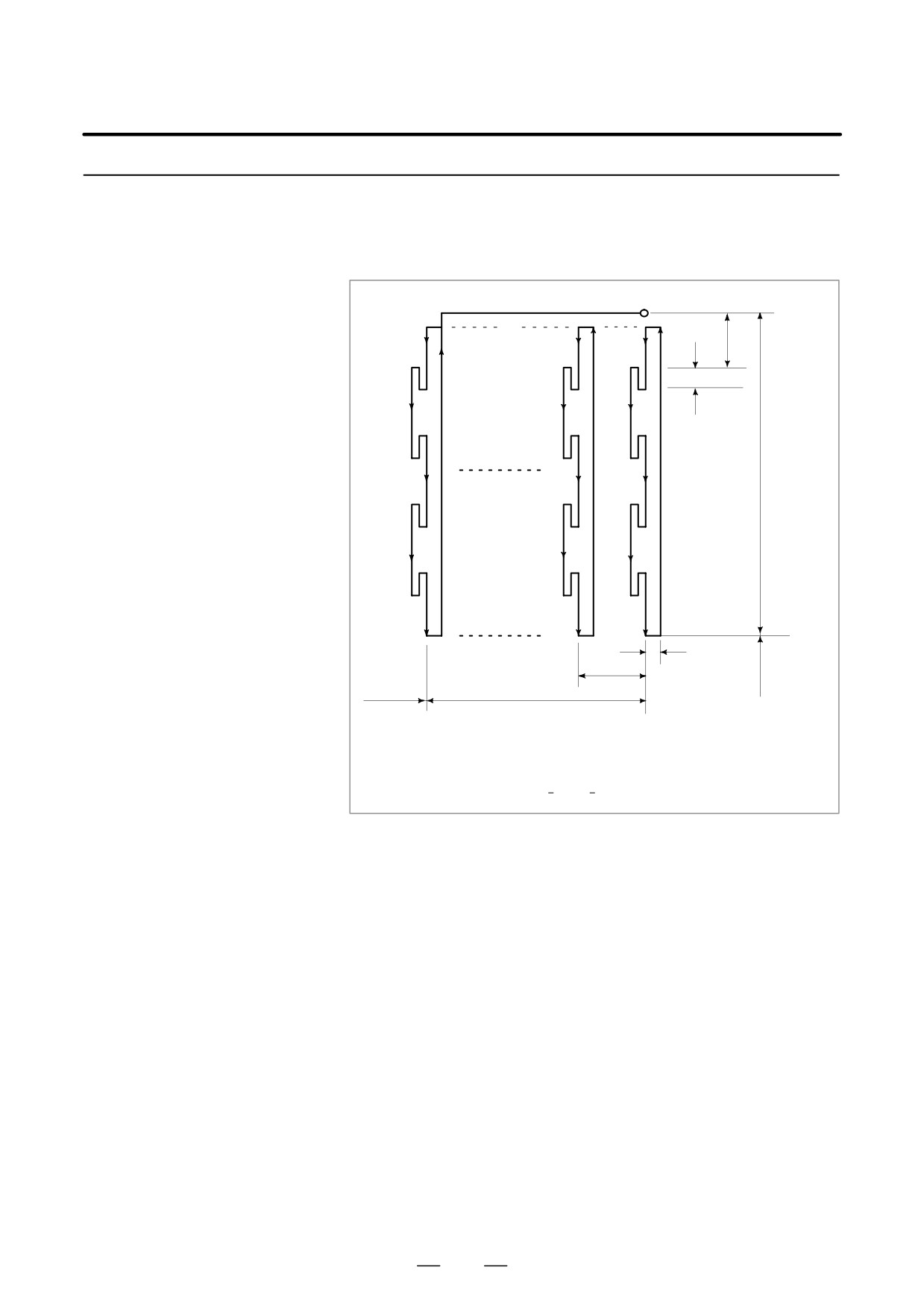
The following program generates the cutting path shown in Fig. 13.2.6.
This is equivalent to G74 except that X is replaced by Z. Chip breaking
Outer Diameter /
is possible in this cycle, and grooving in X axis and peck drilling in X axis
Internal Diameter
(in this case, Z, W, and Q are omitted) are possible.
Drilling Cycle (G75)
(R)
A
Di
(F)
(R)
e
(F)
(R)
U/2
(F)
(R)
(F)
(R)
(F)
Dd
Dk
X
Z
W
G75R (e) ;
G75X(U)_ Z(W)_ P(∆i) Q(∆k) R(∆d) F(f) ;
Fig. 13.2.6
Cutting Path in Outer Diameter / Internal Diameter Drilling Cycle
Both G74 and G75 are used for grooving and drilling, and permit the tool
to relief automatically. Four symmetrical patterns are considered,
respectively.
176
13. FUNCTIONS TO SIMPLIFY
B-63524EN/01
PROGRAMMING
PROGRAMMING
13.2.7
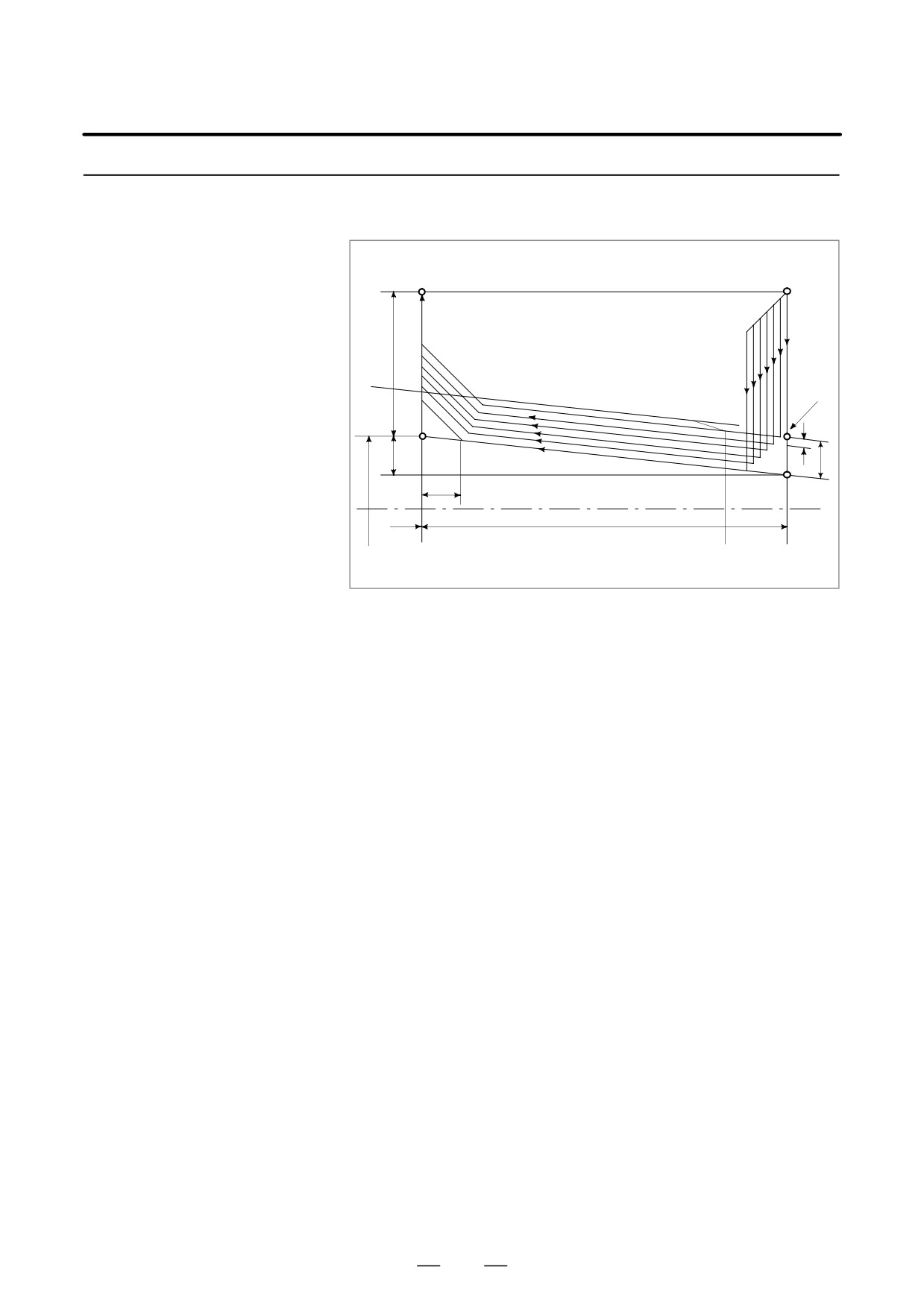
The thread cutting cycle as shown in Fig.13.2.7 is programmed by the
G76 command.
Multiple Thread Cutting
Cycle (G76)
E
(R)
A
U/2
(R)
(F)
B
Dd
i
D
k
r
C
X
Z
W
Fig. 13.2.7 Cutting Path in Multiple thread cutting cycle
177
13. FUNCTIONS TO SIMPLIFY
PROGRAMMING
PROGRAMMING
B-63524EN/01
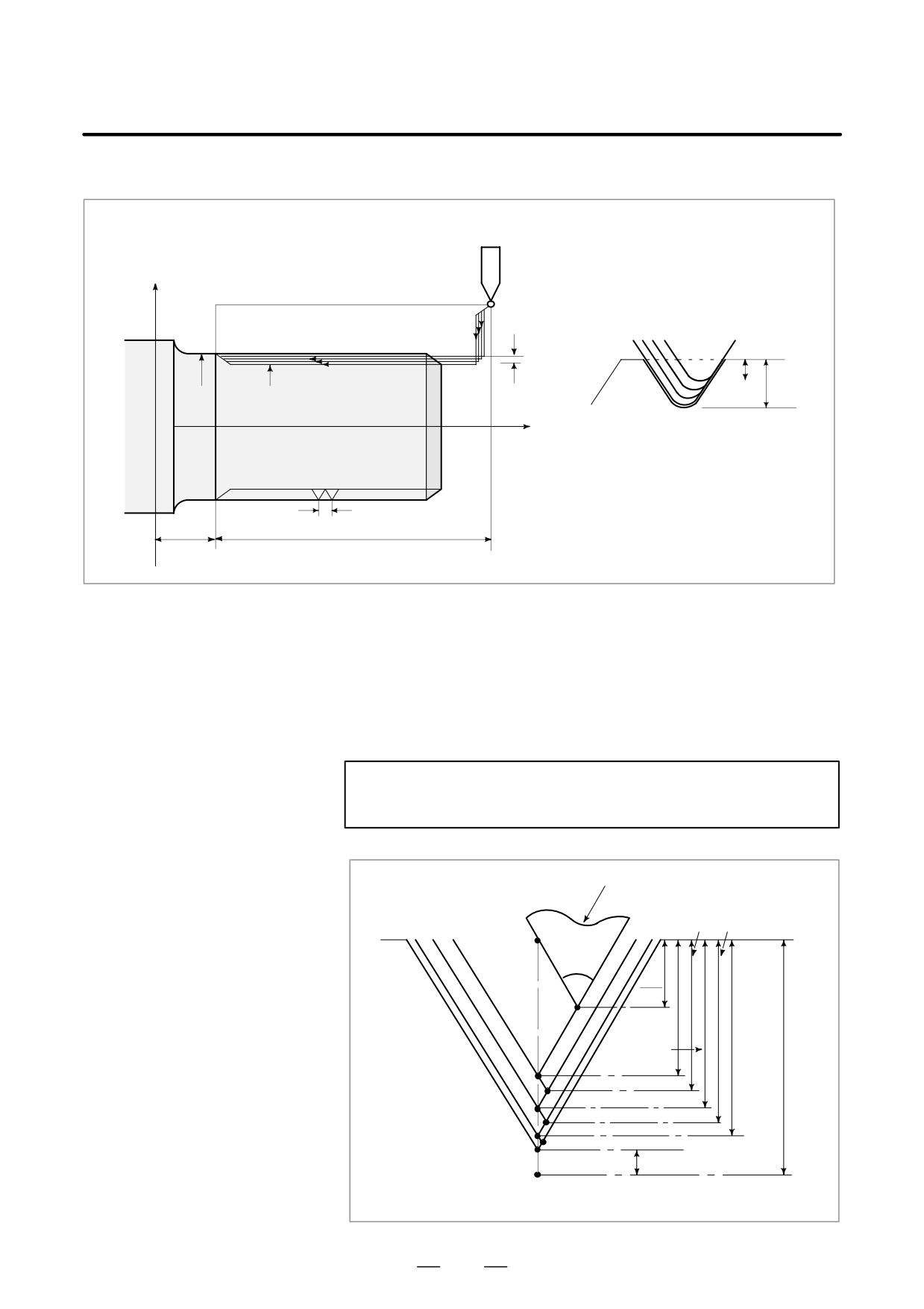
Tool tip
ÅÅ
ÅÅ
B
ÅÅ
ÅÅ
∆ d
ÅÅÅ aÅÅ
∆pn
1st
k
2nd
ÅÅÅÅÅ
3rd
th
ÅÅÅn
d
ÅÅ
Å
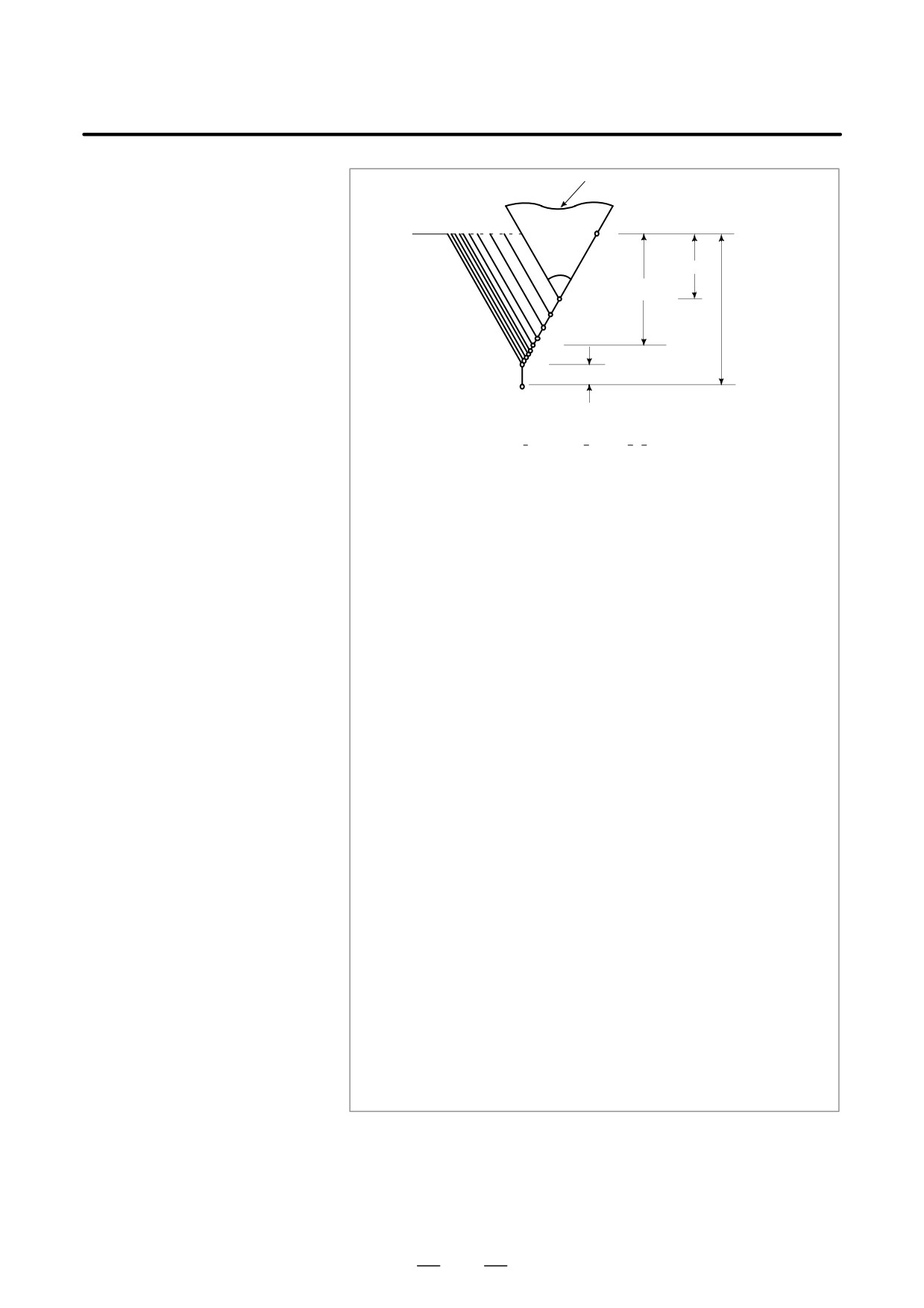
G76P (m) (r) (a) Q (∆d min) R(d);
G76X (u) _ Z(W) _ R(i) P(k) Q(∆d) F(L) ;
m
; Repetitive count in finishing (1 to 99)
This designation is modal and is not changed until the other value is
designated. Also this value can be specified by the parameter No.
5142, and the parameter is changed by the program command.
r
: Chamfering amount
When the thread lead is expressed by L, the value of L can be set from
0.0L to 9.9L in 0.1L increment (2-digit number from 00 to 90).
This designation is modal and is not changed until the other value is
designated. Also this value can be specified by the parameter No.
5130, and the parameter is changed by the program command.
a
: Angle of tool tip
One of six kinds of angle, 805, 605, 555, 305, 295, and 05, can be
selected, and specified by 2-digit number.
This designation is modal and is not changed until the other value is
designated. Also this value can be specified by the parameter No.
5143, and the parameter is changed by the program command.
m, r, and a are specified by address P at the same time.
(Example)
When m=2, r=1.2L, a=60°, specify as shown below (L is lead of thread).
02
12
60
P
m
r
a
∆dmin : Minimum cutting depth (specified by the radius value)
When the cutting depth of one cycle operation (∆d - ∆d -1) becomes
smaller than this limit, the cutting depth is clamped at this value. This
designation is modal and is not changed until the other value is
designated. Also this value can be specified by parameter No.
5140, and the parameter is changed by the program command.
d
: Finishing allowance
This designation is modal and is not changed until the other value
is designated. Also this value can be specified by parameter No.
5141, and the parameter is changed by the program command.
i
: Difference of thread radius If i = 0, ordinary straight thread cutting
can be made.
k
: Height of thread
This value is specified by the radius value.
nd
: Depth of cut in 1st cut (radius value)
L
: Lead of thread (same as G32).
Fig. 13.2.7 (b) Detail of cutting
178
13. FUNCTIONS TO SIMPLIFY
B-63524EN/01
PROGRAMMING
PROGRAMMING
D Thread cutting cycle
When feed hold is applied during threading in the multiple thread cutting
retract
cycle (G76), the tool quickly retracts in the same way as in chamfering
performed at the end of the thread cutting cycle. The tool goes back to
the start point of the cycle. When cycle start is triggered, the multiple
thread cutting cycle resumes.
Without this retraction function, when feed hold is applied during
threading, the tool goes back to the start point of the cycle after threading
is completed.
See notes in 13.1.2.
NOTE
1
The meanings of the data specified by address P, Q, and R
determined by the presence of X (U) and X (W).
2
The cycle machining is performed by G76 command with X
(U) and Z (W) specification.
By using this cycle , one edge cutting is performed and the
load on the tool tip is reduced.
Making the cutting depth nd for the first path, and ndn for
the nth path, cutting amount per one cycle is held constant.
Four symmetrical patterns are considered corresponding to
the sign of each address.
The internal thread cutting is available. In the above figure,
the feed rate between C and D is specified by address F, and
in the other path, at rapid traverse. The sign of incremental
dimensions for the above figure is as follows:
U, W : minus (determined by the direction of the tool path
AC and CD.)
R : minus (determined by the direction of the tool path
AC.)
P : plus (always)
Q : plus (always)
3
Notes on thread cutting are the same as those on G32
thread cutting and G92 thread cutting cycle.
4
The designation of chamfering is also effective for G92
thread cutting cycle.
5
The tool returns to the cycle start point at that time (cutting
depth ndn) as soon as the feed hold status is entered during
thread cutting when the “Thread Cutting Cycle retract”
option is used.
179
13. FUNCTIONS TO SIMPLIFY
PROGRAMMING
PROGRAMMING
B-63524EN/01
Examples
Multiple repetitive cycle (G76)
X axis
0
1.8
1.8
ÔÔÔ
3.68
ϕ68
ϕ60.64
ÔÔ
Z axis
ÅÅ
G80 X80.0 Z130.0 ;
6
G76 P011060 Q100 R200 ;
G76 X60640 Z25000 P3680 Q1800 F6.0 ;
25
105
D Staggered thread cutting
Specifying P2 can perform staggered thread cutting with a constant depth
of cut.
Example: G76 X60640 Z25000 K3680 D1800 F6.0 A60 P2;
For staggered thread cutting, always use the FS15 tape format (see
Section 18.5).
If the depth of cut in one cycle is less than dmin (specified in parameter
No. 5140), the depth of cut is clamped at ∆dmin.
NOTE
Multiple repetitive cycle II is required.
Tool nose
(Ǹ2⋅Ǹ4) D/2
(Ǹ 4⋅ Ǹ6) D/2
Hn
a
Ǹ2⋅D
2
H1
Ǹ2⋅D
K
Ǹ4⋅D
H2
H3
H4
H5
H6
H7
H8
α (Finishing allowance)
H9
Staggered thread cutting with a constant depth of cut
180
13. FUNCTIONS TO SIMPLIFY
B-63524EN/01
PROGRAMMING
PROGRAMMING
13.2.8
1.
In the blocks where the multiple repetitive cycle are commanded, the
addresses P, Q, X, Z, U, W, and R should be specified correctly for each
Notes on Multiple
block.
Repetitive Cycle
2.
In the block which is specified by address P of G71, G72 or G73, G00
(G70-G76)
or G01 group should be commanded. If it is not commanded, P/S
alarm No. 65 is generated.
3.
In MDI mode, G70, G71, G72, or G73 cannot be commanded. If it is
commanded, P/S alarm No. 67 is generated. G74, G75, and G76 can
be commanded in MDI mode.
4.
In the blocks in which G70, G71, G72, or G73 are commanded and
between the sequence number specified by P and Q, M98 (subprogram
call) and M99 (subprogram end) cannot be commanded.
5.
In the blocks between the sequence number specified by P and Q, the
following commands cannot be specified.
⋅One shot G code except for G04 (dwell)
⋅01 group G code except for G00, G01, G02, and G03
⋅06 group G code
⋅M98 / M99
6.
While a multiple repetitive cycle (G70AG76) is being executed, it is
possible to stop the cycle and to perform manual operation. But, when
the cycle operation is restarted, the tool should be returned to the
position where the cycle operation is stopped.
If the cycle operation is restarted without returning to the stop position,
the movement in manual operation is added to the absolute value, and
the tool path is shifted by the movement amount in manual operation.
7.
When G70, G71, G72, or G73 is executed, the sequence number
specified by address P and Q should not be specified twice or more in
the same program.
8.
The blocks between the sequence number specified by P and Q on the
multiple repetitive cycle must not be programmed by using “Direct
Drawing Dimensions Programming” or “Chamfering and Corner R”.
9.
G74, G75, and G76 also do not support the input of a decimal point
for P or Q. The least input increments are used as the units in which
the amount of travel and depth of cut are specified.
10.When #1 = 2500 is executed using a custom macro, 2500.000 is
assigned to #1. In such a case, P#1 is equivalent to P2500.
11.Tool nose radius compensation cannot be applied to G71, G72, G73,
G74, G75, G76, or G78.
12.The multiple repetitive cycle cannot be executing during DNC
operation.
13.Interruption type custom macro cannot be executed during executing
the multiple repetitive cycle.
14.The multiple repetitive cycle cannot be executing during Advanced
Preview Control mode.
181
13. FUNCTIONS TO SIMPLIFY
PROGRAMMING
PROGRAMMING
B-63524EN/01
The canned cycle for drilling simplifies the program normally by
13.3
directing the machining operation commanded with a few blocks, using
CANNED CYCLE FOR
one block including G code.
DRILLING (G80-G89)
This canned cycle conforms to JIS B 6314.
Following is the canned cycle table.
Table 13.3 (a) Canned Cycles
G code
Drilling
Hole machining
Operation in the
Retraction operation
Applications
axis
operation (- direction)
bottom hole position
(+ direction)
G80
____
_____
_____
___
Cancel
G83
Z axis
Cutting feed / intermittent
Dwell
Rapid traverse
Front drilling cycle
G84
Z axis
Cutting feed
Dwell→spindle CCW
Cutting feed
Front tapping cycle
G85
Z axis
Cutting feed
_____
Cutting feed
Front boring cycle
G87
X axis
Cutting feed / intermittent
Dwell
Rapid traverse
Side drilling cycle
G88
X axis
Cutting feed
Dwell→Spindle CCW
Cutting feed
Side tapping cycle
G89
X axis
Cutting feed
Dwell
Cutting feed
Side boring cycle
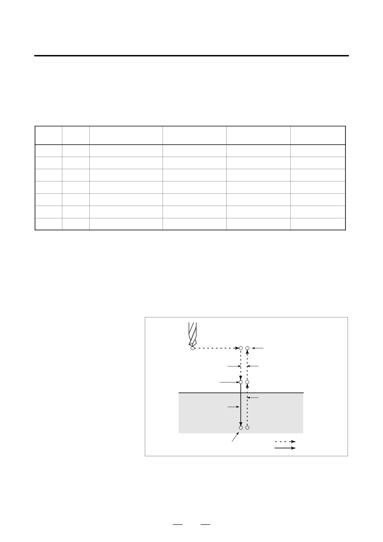
In general, the drilling cycle consists of the following six operation
sequences.
Operation 1 Positioning of X (Z) and C axis
Operation 2 Rapid traverse up to point R level
Operation 3 Hole machining
Operation 4 Operation at the bottom of a hole
Operation 5
Retraction to point R level
Operation 6
Rapid traverse up to the initial point
Operation 1
Initial level
Operation 2
Operation 6
Point R level
Operation 5
Operation 3
Rapid traverse
Operation 4
Feed
Fig. 13.3 Drilling Cycle Operation Sequence
182
13. FUNCTIONS TO SIMPLIFY
B-63524EN/01
PROGRAMMING
PROGRAMMING
Explanations
D Positioning axis and
A drilling G code specifies positioning axes and a drilling axis as shown
drilling axis
below. The C-axis and X- or Z-axis are used as positioning axes. The
X- or Z-axis, which is not used as a positioning axis, is used as a drilling
axis.
Although canned cycles include tapping and boring cycles as well as
drilling cycles, in this chapter, only the term drilling will be used to refer
to operations implemented with canned cycles.
Table13.3 (b) Positioning axis and drilling axis
G code
Positioning plane
Drilling axis
G83, G84, G85
X axis, C axis
Z axis
G87, G88, G89
Z axis, C axis
X axis
G83 and G87, G84 and G88, and G85 and G89 have the same function
respectively except for axes specified as positioning axes and a drilling
axis.
D Drilling mode
G83AG85 / G87A89 are modal G codes and remain in effect until
canceled. When in effect, the current state is the drilling mode.
Once drilling data is specified in the drilling mode, the data is retained
until modified or canceled.
Specify all necessary drilling data at the beginning of canned cycles; when
canned cycles are being performed, specify data modifications only.
D Return point level
In G code system A, the tool returns to the initial level from the bottom
G98/G99
of a hole. In G code system B or C, specifying G98 returns the tool to the
initial level from the bottom of a hole and specifying G99 returns the tool
to the point-R level from the bottom of a hole.
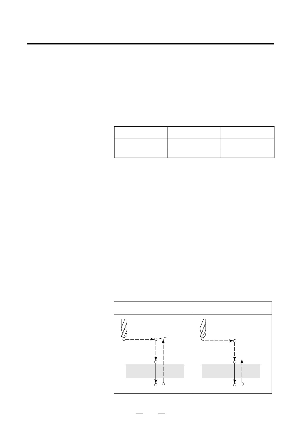
The following illustrates how the tool moves when G98 or G99 is
specified. Generally, G99 is used for the first drilling operation and G98
is used for the last drilling operation.
The initial level does not change even when drilling is performed in the
G99 mode.
G98 (Return to initial level)
G99 (Return to point R level)
Initial level
Point R level
183
13. FUNCTIONS TO SIMPLIFY
PROGRAMMING
PROGRAMMING
B-63524EN/01
D Number of repeats
To repeat drilling for equally-spaced holes, specify the number of repeats
in K_.
K is effective only within the block where it is specified.
Specify the first hole position in incremental mode.
If it is specified in absolute mode, drilling is repeated at the same position.
Number of repeats K The maximum command value = 9999
When K0 is specified with parameter K0E (parameter No. 5102 #4) set
to 0, drilling is performed once.
When K0 is specified with parameter K0E (parameter No. 5102 #4) set
to 1, drilling data is just stored without drilling being performed.
D M code used for C-axis
When an M code specified in parameter No. 5110 for C-axis clamp /
clamp/unclamp
unclamp is coded in a program, the CNC issues the M code for C-axis
clamp after the tool is positioned and before the tool is fed in rapid traverse
to the point-R level. The CNC also issues the M code for C-axis unclamp
(the M code for C-axis clamp +1) after the tool retracts to the point-R
level. The tool dwells for the time specified in parameter No. 5111.
D Cancel
To cancel a canned cycle, use G80 or a group 01 G code.
Group 01 G codes
G00 : Positioning (rapid traverse)
G01 : Linear interpolation
G02 : Circular interpolation (CW)
G03 : Circular interpolation (CCW)
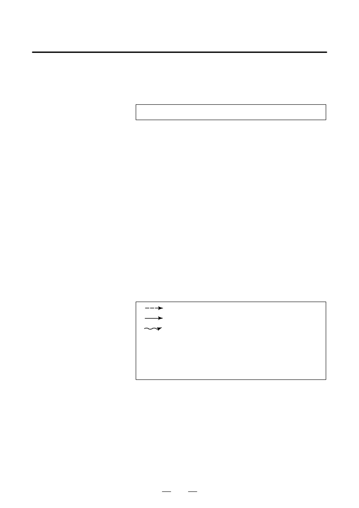
D Symbols in figures
Subsequent sections explain the individual canned cycles. Figures in
these explanations use the following symbols:
Positioning (rapid traverse G00)
Cutting feed (linear interpolation G01)
Manual feed
P1
Dwell specified in the program
P1
Dwell specified in parameter No.5111
Mα
Issuing the M code for C-axis clamp
(The value of a is specified with parameter No. 5110.)
M (α+1) Issuing the M code for C-axis unclamp
184
13. FUNCTIONS TO SIMPLIFY
B-63524EN/01
PROGRAMMING
PROGRAMMING
CAUTION
D In each canned cycle,
R_ (distance between the initial level and point R) is always
handled as a radius.
Z_ or X_ (distance between point R and the bottom of the
hole) is, however, handled either as a diameter or radius,
depending on the specification.
D For the B or C G-code system, G90 or G91 can be used to
select an incremental or absolute command for hole
position data (X, C or Z, C), the distance from point R to the
bottom of the hole (Z or X), and the distance from the initial
level to the point R level (R).
185
13. FUNCTIONS TO SIMPLIFY
PROGRAMMING
PROGRAMMING
B-63524EN/01
13.3.1
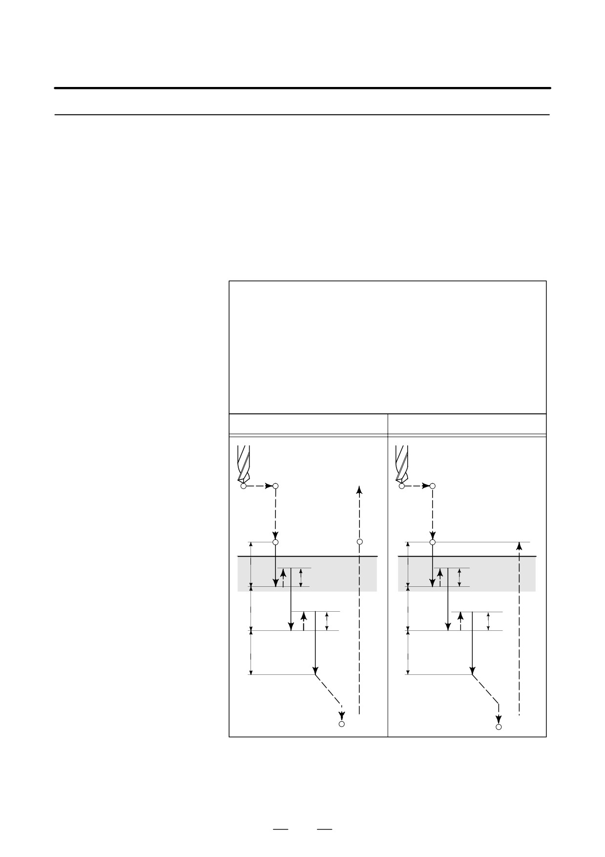
The peck drilling cycle or high-speed peck drilling cycle is used
depending on the setting in RTR, bit 2 of parameter No. 5101. If depth
Front Drilling Cycle
of cut for each drilling is not specified, the normal drilling cycle is used.
(G83) / Side Drilling
Cycle (G87)
D High-speed peck
This cycle performs high-speed peck drilling. The drill repeats the cycle
drilling cycle (G83, G87)
of drilling at the cutting feedrate and retracting the specified retraction
(parameter RTR
distance intermittently to the bottom of a hole. The drill draws cutting
(No. 5101#2) =0)
chips out of the hole when it retracts.
Format
G83 X(U)_ C(H)_ Z(W)_ R_ Q_ P_ F_ K_ M_ ;
or
G87 Z(W)_ C(H)_ X(U)_ R_ Q_ P_ F_ K_ M_ ;
X_ C_ or Z_ C_ : Hole position data
Z_ or X_
: The distance from point R to the bottom of the hole
R_ : The distance from the initial level to point R level
Q_ : Depth of cut for each cutting feed
P_ : Dwell time at the bottom of a hole
F_ : Cutting feedrate
K_ : Number of repeats (When it is needed)
M_ : M code for C-axis clamp (When it is needed.)
G83 or G87 (G98 mode)
G83 or G87 (G99 mode)
Mα
Mα
Initial level
M (a+1), P2
Point R
M (α+1)
Point R
Point R
P2
q
q
d
d
q
q
d
d
q
q
P1
Point Z
P1
Point Z
Mα
: M code for C-axis clamp
M(α+1)
: M code for C-axis unclamp
P1
: Dwell specified in the program
P2
: Dwell specified in parameter No. 5111
d
: Retraction distance specified in parameter No. 5114
186
13. FUNCTIONS TO SIMPLIFY
B-63524EN/01
PROGRAMMING
PROGRAMMING
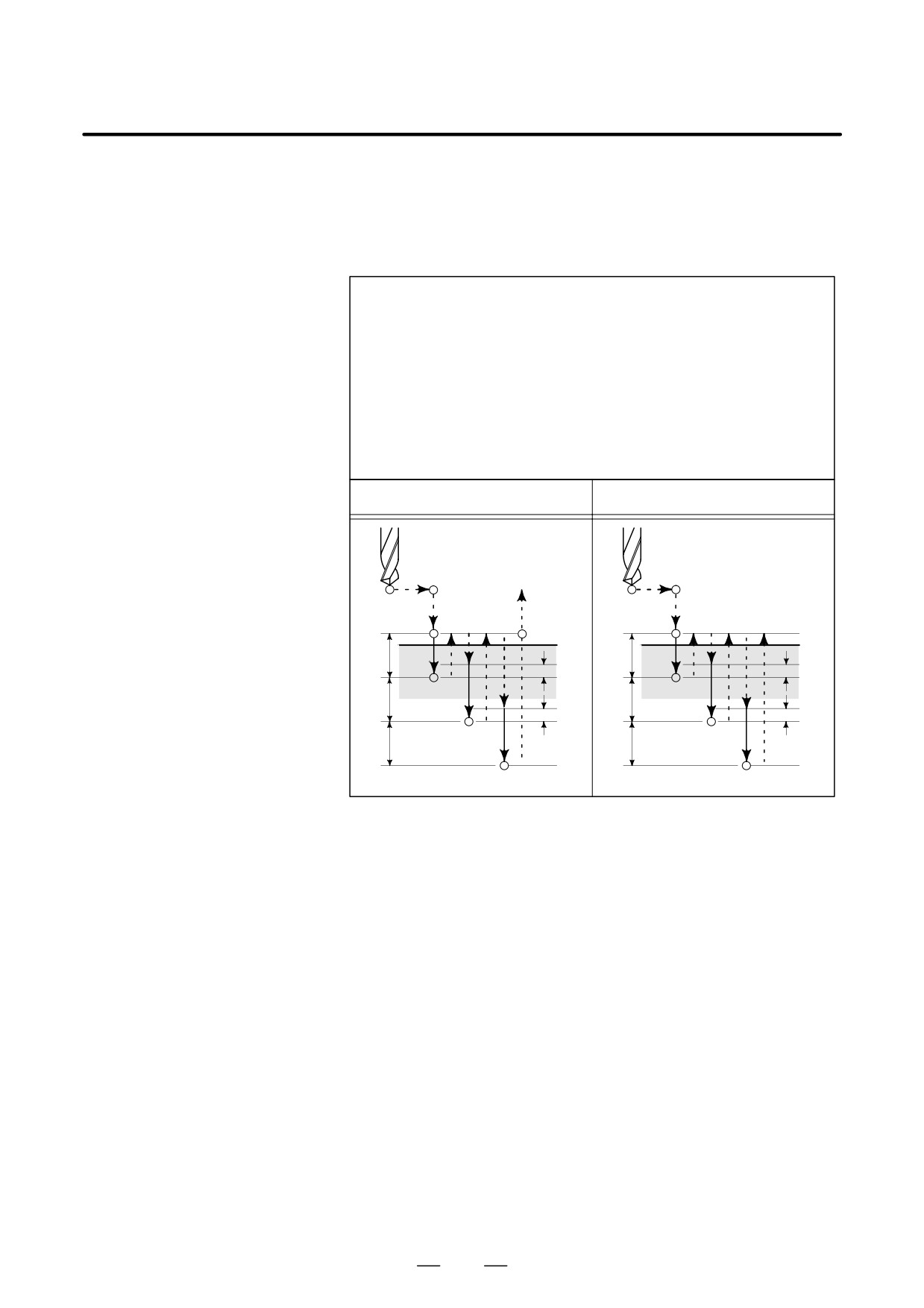
D Peck drilling cycle
(G83, G87) (parameter
No. 5101#2 =1)
Format
G83 X(U)_ C(H)_ Z(W)_ R_ Q_ P_ F_ K_ M_ ;
or
G87 Z(W)_ C(H)_ X(U)_ R_ Q_ P_ F_ K_ M_ ;
X_ C_ or Z_ C_ : Hole position data
Z_ or X_
: The distance from point R to the bottom of the hole
R_ : The distance from the initial level to point R level
Q_ : Depth of cut for each cutting feed
P_ : Dwell time at the bottom of a hole
F_ : Cutting feedrate
K_ : Number of repeats (When it is needed.)
M_ : M code for C-axis clamp (When it is needed.)
G83 or G87 (G98 mode)
G83 or G87 (G99 mode)
Mα
Initial level
Mα
M (a+1), P2
Point R
M (a+1),
Point R
Point R
P2
q
q
d
d
q
q
d
d
q
q
Point Z
Point Z
P1
P1
Mα
: M code for C-axis clamp
M(α+1)
: M code for C-axis unclamp
P1
: Dwell specified in the program
P2
: Dwell specified in parameter No. 5111
d
: Retraction distance specified in parameter No. 5114
Examples
M51 ;
Setting C-axis index mode ON
M3 S2000 ;
Rotating the drill
G00 X50.0 C0.0 ;
Positioning the drill along the X- and
C-axes
G83 Z-40.0 R-5.0 Q5000 F5.0 M31 ; Drilling hole 1
C90.0 Q5000 M31 ;
Drilling hole 2
C180.0 Q5000 M31 ;
Drilling hole 3
C270.0 Q5000 M31 ;
Drilling hole 4
G80 M05 ;
Canceling the drilling cycle and
stopping drill rotation
M50 ;
Setting C-axis index mode off
187
13. FUNCTIONS TO SIMPLIFY
PROGRAMMING
PROGRAMMING
B-63524EN/01
NOTE
If the depth of cut for each cutting feed
(Q) is not
commanded, normal drilling is performed.
(See the
description of the drilling cycle.)
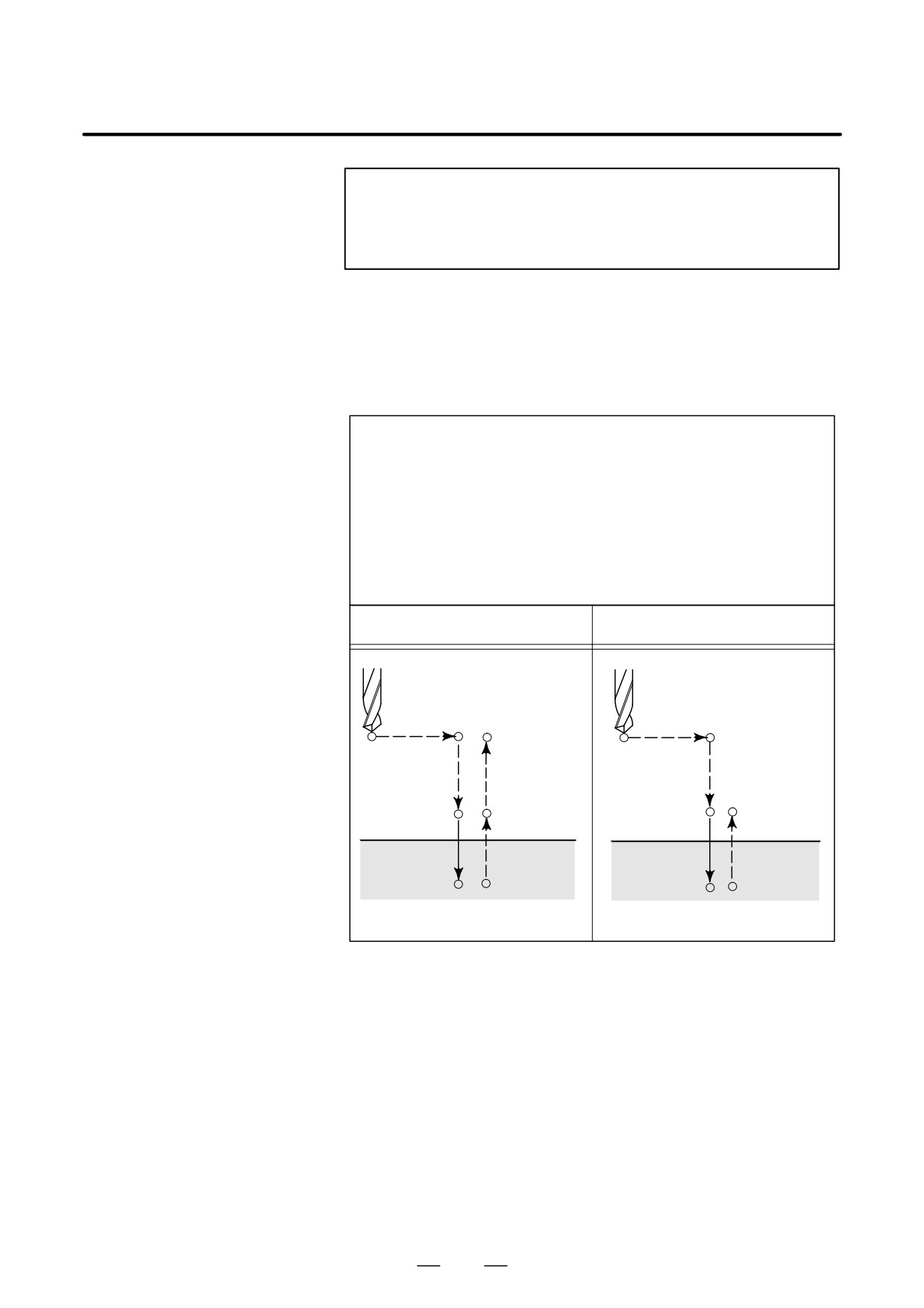
D Drilling cycle
If depth of cut is not specified for each drilling, the normal drilling cycle
(G83 or G87)
is used. The tool is then retracted from the bottom of the hole in rapid
traverse.
Format
G83 X(U)_ C(H)_ Z(W)_ R_ P_ F_ K_ M_ ;
or
G87 Z(W)_ C(H)_ X(U)_ R_ P_ F_ K_ M_ ;
X_ C_ or Z_ C_ : Hole position data
Z_ or X_
: The distance from point R to the bottom of the hole
R_ : The distance from the initial level to point R level
P_ : Dwell time at the bottom of a hole
F_ : Cutting feedrate
K_ : Number of repeats (When it is needed.)
M_ : M code for C-axis clamp (When it is needed.)
G83 or G87 (G98 mode)
G83 or G87 (G99 mode)
Mα
Mα
Initial level
Point R level
Point R level
M (a+1), P2
M (a+1), P2
Point Z
Point Z
P1
P1
Mα
: M code for C-axis clamp
M(a+1)
: M code for C-axis unclamp
P1
: Dwell specified in the program
P2
: Dwell specified in parameter No. 5111
188