FANUC Series 0i-MC. OPERATOR’S MANUAL - page 18
B-64124EN/01
OPERATION
4. AUTOMATIC OPERATION
D Single block
When single block operation is ON during movement to the restart
position, operation stops every time the tool completes movement along
an axis. When operation is stopped in the single block mode, MDI
intervention cannot be performed.
D Manual intervention
During movement to the restart position, manual intervention can be used
to perform a return operation for an axis if it has not yet been performed
for the axis. A return operation cannot be done further on axes for which
a return has already been completed.
D Reset
Never reset during the time from the start of a search at restart until
machining is restarted. Otherwise, restart must be performed again from
the first step.
D Manual absolute
Regardless of whether machining has started or not, manual operation
must be performed when the manual absolute mode is on.
D Reference position return
If no absolute-position detector (absolute pulse coder) is provided, be
sure to perform reference position return after turning on the power and
before performing restart.
Alarm
Alarm No.
Contents
The specified block number for restarting the program is not
071
found.
After interruption, a coordinate system was set, then P-type
094
restart was specified.
After interruption, the coordinate system shift was changed,
095
then P-type restart was specified.
After interruption, the coordinate system was changed, then
096
P-type restart was specified.
When automatic operation has not been performed since
the power was turned on, emergency stop was released, or
097
P/S alarm 094 to 097 was reset, P-type restart was speci-
fied.
After the power was turned on, restart operation was per-
098
formed without reference position return, but a G28 com-
mand was found in the program.
A move command was specified from the MDI panel during
099
a restart operation.
An erroneous parameter was specififed for restarting a pro-
5020
gram.
WARNING
As a rule, the tool cannot be returned to a correct position under the following conditions.
Special care must be taken in the following cases since none of them cause an alarm:
S Manual operation is performed when the manual absolute mode is OFF.
S Manual operation is performed when the machine is locked.
S When the mirror image is used.
S When manual operation is performed in the course of axis movement for returning operation.
S When the program restart is commanded for a block between the block for skip cutting and
subsequent absolute command block.
493
4. AUTOMATIC OPERATION
OPERATION
B-64124EN/01
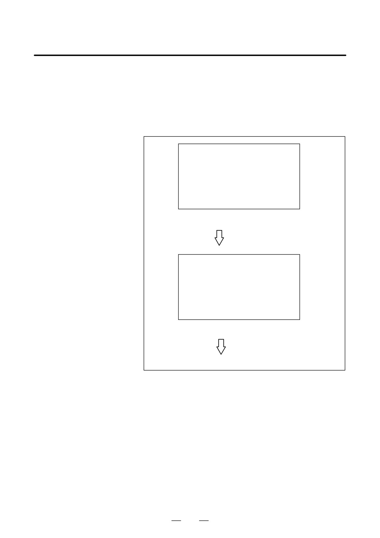
The schedule function allows the operator to select files (programs)
4.5
registered on a floppy-disk in an external input/output device (such as
SCHEDULING
Handy File) and specify the execution order and number of repetitions
FUNCTION
(scheduling) for performing automatic operation.
It is also possible to select only one file from the files in the external
input/output device and execute it during automatic operation.
FILE DIRECTORY
FILE NO.
FILE NAME
0001
O0010
0002
O0020
0003
O0030
0004
O0040
List of files in an external input/output device
Set file number and
number of repetitions.
ORDER FILE NO REPETITION
01
0002
2
02
0003
1
03
0004
3
04
0001
2
Scheduling screen
Executing automatic operation
494
B-64124EN/01
OPERATION
4. AUTOMATIC OPERATION
Procedure for Scheduling Function
Procedure
D Procedure for executing
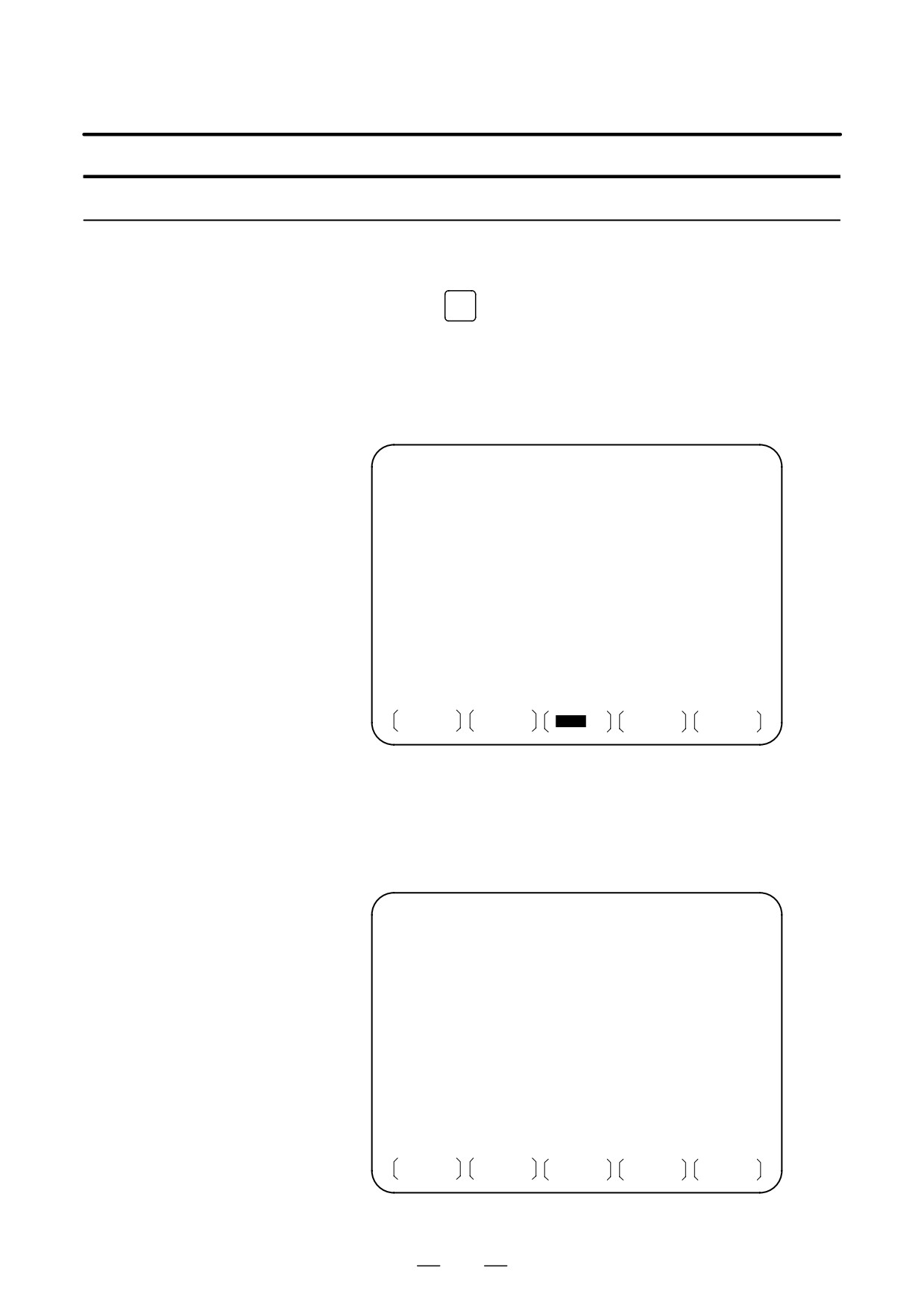
1
Press the MEMORY switch on the machine operator’s panel, then
one file
press the
PROG
function key on the MDI panel.
2
Press the rightmost soft key (continuous menu key), then press the
[FL. SDL] soft key. A list of files registered in the Floppy Cassette is
displayed on screen No. 1. To display more files that are not
displayed on this screen, press the page key on the MDI panel. Files
registered in the Floppy Cassette can also be displayed successively.
FILE DIRECTORY
O0001 N00000
CURRENT SELECTED : SCHEDULE
NO. FILE NAME
(METER) VOL
0000
SCHEDULE
0001
PARAMETER
58.5
0002
ALL PROGRAM
11.0
0003
O0001
1.9
0004
O0002
1.9
0005
O0010
1.9
0006
O0020
1.9
0007
O0040
1.9
0008
O0050
1.9
MEM * * * *
* * *
* * *
19 : 14 : 47
PRGRM
DIR
SCHDUL
(OPRT)
Screen No.1
3
Press the [(OPRT)] and [SELECT] soft keys to display “SELECT
FILE NO.” (on screen No. 2). Enter a file number, then press the [F
SET] and [EXEC] soft keys. The file for the entered file number is
selected, and the file name is indicated after
“CURRENT
SELECTED:”.
FILE DIRECTORY
O0001 N00000
CURRENT SELECTED:O0040
NO. FILE NAME
(METER) VOL
0000
SCHEDULE
0001
PARAMETER
58.5
0002
ALL PROGRAM
11.0
0003
O0001
1.9
0004
O0002
1.9
0005
O0010
1.9
0006
O0020
1.9
0007
O0040
1.9
0008
O0050
1.9
SELECT FILE NO.=7
>_
MEM * * * *
* * *
* * *
19 : 17 : 10
F SET
EXEC
Screen No.2
495
4. AUTOMATIC OPERATION
OPERATION
B-64124EN/01
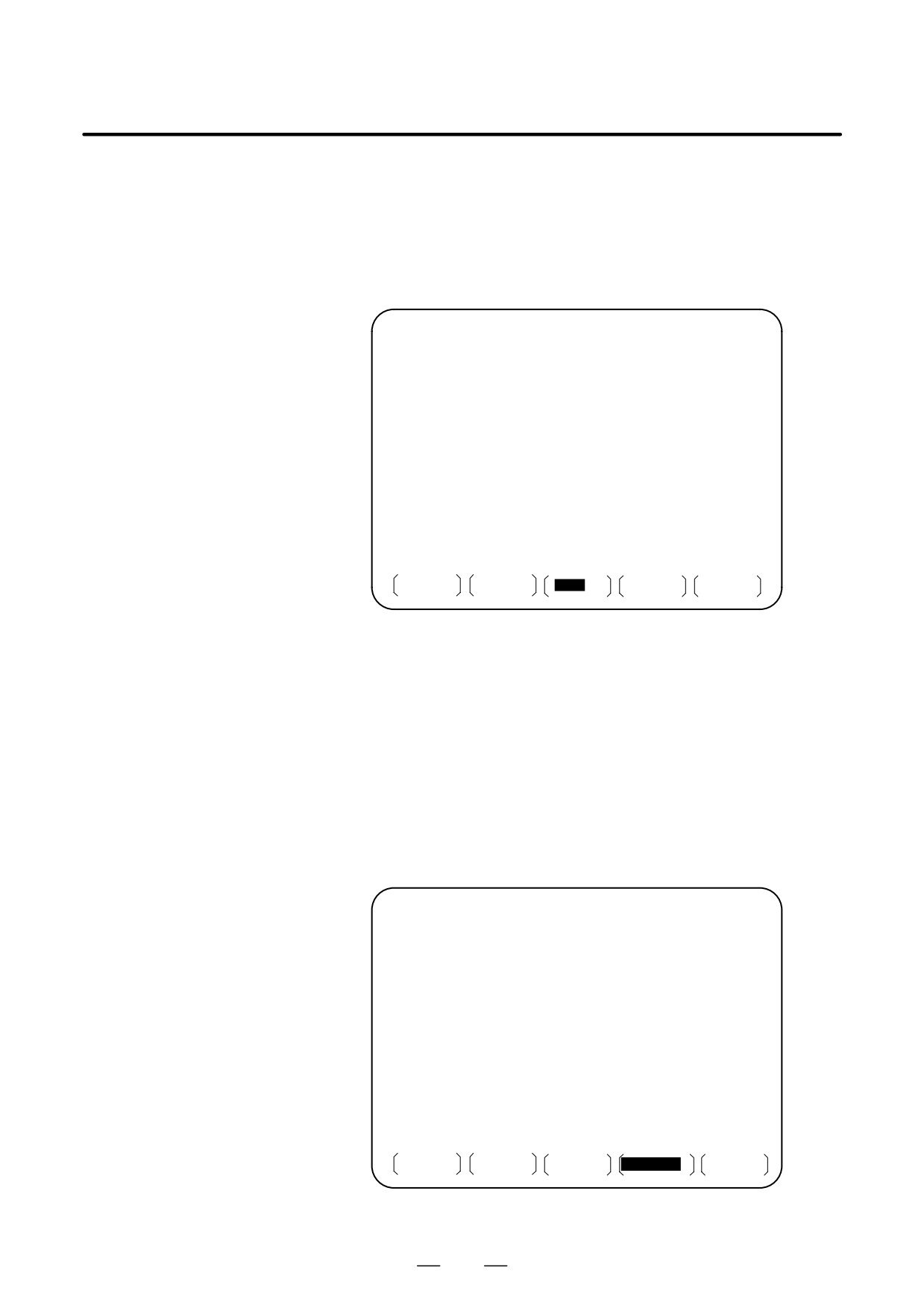
4
Press the REMOTE switch on the machine operator’s panel to enter
the RMT mode, then press the cycle start switch. The selected file is
executed. For details on the REMOTE switch, refer to the manual
supplied by the machine tool builder. The selected file number is
indicated at the upper right corner of the screen as an F number
(instead of an O number).
FILE DIRECTORY
F0007 N00000
CURRENT SELECTED:O0040
RMT
* * * *
* * *
* * *
13 : 27 : 54
PRGRM
DIR
SCHDUL
(OPRT)
Screen No.3
D Procedure for executing
1
Display the list of files registered in the Floppy Cassette. The display
the scheduling function
procedure is the same as in steps 1 and 2 for executing one file.
2
On screen No. 2, press the [(OPRT)] and [SELECT] soft keys to
display “SELECT FILE NO.”
3
Enter file number 0, and press the [F SET], and [EXEC] soft keys.
“SCHEDULE” is indicated after “CURRENT SELECTED:”.
4
Press the leftmost soft key (return menu key) and the [SCHDUL] soft
key. Screen No. 4 appears.
FILE DIRECTORY
F0000 N02000
ORDER FILE NO. REQ.REP CUR.REP
01
02
03
04
05
06
07
08
09
10
>_
MEM * * * *
* * *
* * *
22 : 07 : 00
PRGRM
DIR
SCHDUL
(OPRT)
Screen No.4
496
B-64124EN/01
OPERATION
4. AUTOMATIC OPERATION
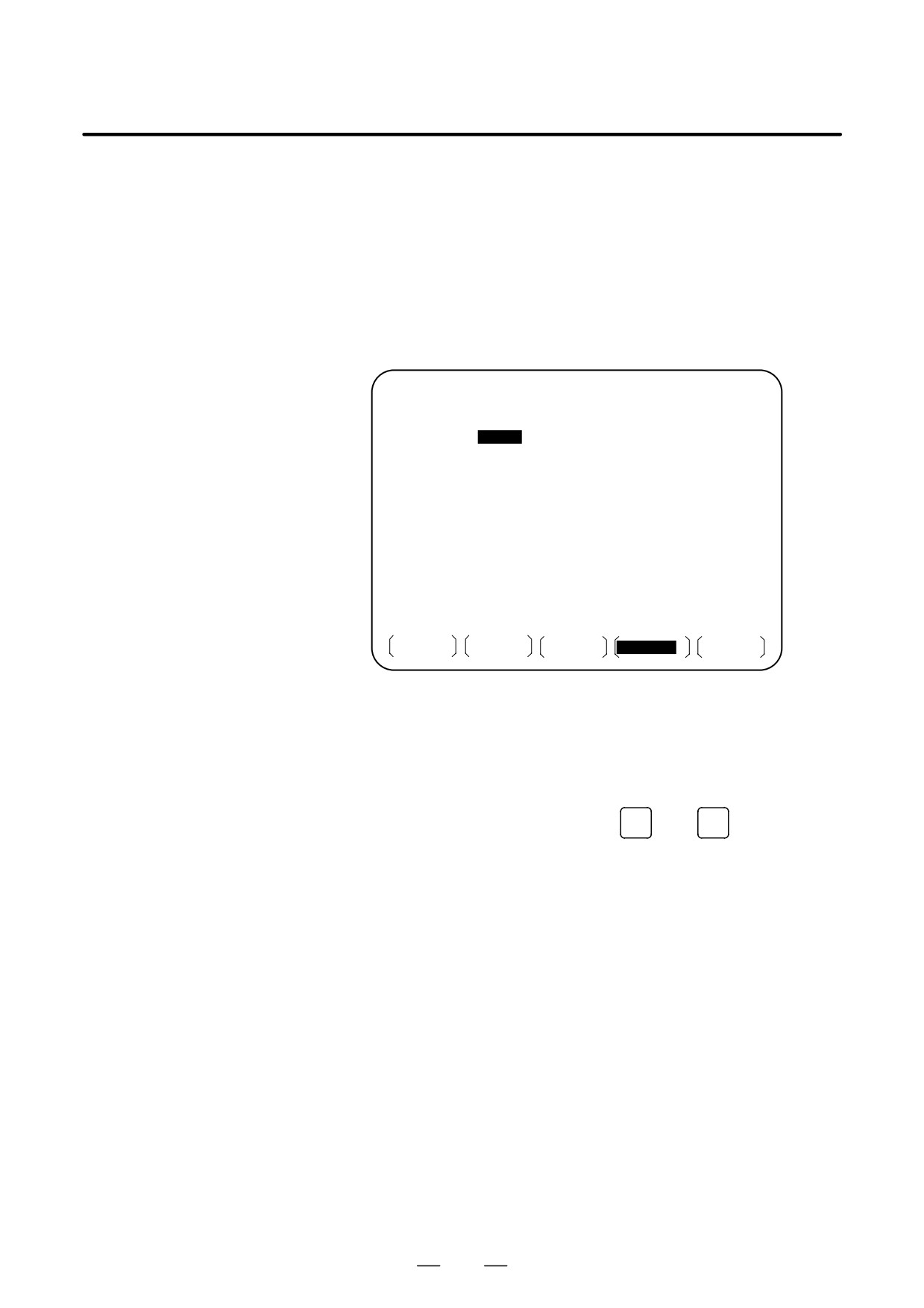
Move the cursor and enter the file numbers and number of repetitions
in the order in which to execute the files. At this time, the current
number of repetitions “CUR.REP” is 0.
5
Press the REMOTE switch on the machine operator’s panel to enter
the RMT mode, then press the start switch. The files are executed in
the specified order. When a file is being executed, the cursor is
positioned at the number of that file.
The current number of repetitions CUR.REP is increased when M02
or M30 is executed in the program being run.
FILE DIRECTORY
O0000 N02000
ORDER FILE NO.
REQ.REP CUR.REP
01
0007
5
5
02
0003
23
23
03
0004
9999
156
04
0005
LOOP
0
05
06
07
08
09
10
RMT
* * * *
* * *
* * *
10 : 10 : 40
PRGRM
DIR
SCHDUL
(OPRT)
Screen No.5
Explanations
D Specifying no file
If no file number is specified on screen No. 4 (the file number field is left
number
blank), program execution is stopped at that point. To leave the file
number field blank, press numeric key
0
then
INPUT
D Endless repetition
If a negative value is set as the number of repetitions, <LOOP> is
displayed, and the file is repeated indefinitely.
D Clear
When the [(OPRT)], [CLEAR], and [EXEC] soft keys are pressed on
screen No. 4, all data is cleared. However, these keys do not function
while a file is being executed.
D Return to the program
When the soft key [PRGRM] is pressed on screen No. 1, 2, 3, 4, or 5, the
screen
program screen is displayed.
Restrictions
D Number of repetitions
Up to 9999 can be specified as the number of repetitions. If 0 is set for a
file, the file becomes invalid and is not executed.
D Number of files
By pressing the page key on screen No. 4, up to 20 files can be registered.
registered
D M code
When M codes other than M02 and M30 are executed in a program, the
current number of repetitions is not increased.
497
4. AUTOMATIC OPERATION
OPERATION
B-64124EN/01
D Displaying the floppy
During the execution of file, the floppy directory display of background
disk directory during file
editing cannot be referenced.
execution
D Restarting automatic
To resume automatic operation after it is suspended for scheduled
operation
operation, press the reset button.
Alarm
Alarm No.
Description
086
An attempt was made to execute a file that was not regis-
tered in the floppy disk.
210
M198 and M099 were executed during scheduled opera-
tion, or M198 was executed during DNC operation.
498
B-64124EN/01
OPERATION
4. AUTOMATIC OPERATION
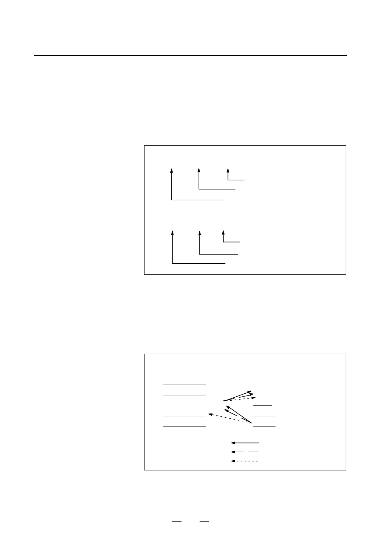
The subprogram call function is provided to call and execute subprogram
4.6
files stored in an external input/output device(Handy File, FLOPPY
SUBPROGRAM
CASSETTE, FA Card)during memory operation.
CALL FUNCTION
When the following block in a program in CNC memory is executed, a
(M198)
subprogram file in the external input/output device is called:
Format
1. FS10/11 tape format
M198 Pffff L∆∆∆∆ ;
Number of repetitions
File number for a file in the I/O device
I/O devices call instruction
2. Other than FS10/11 tape format
M198 Pffff ∆∆∆∆ ;
File number for a file
in the I/O device
Number of repetitions
I/O devices call instruction
Explanation
The subprogram call function is enabled when parameter No.0102 for the
input/output device is set to 3. Either format 1 or 2 can be used. A different
M code can be used for a subprogram call depending on the setting of
parameter No.6030. In this case, M198 is executed as a normal M code.
The file number is specified at address P. If the SBP bit (bit 2) of parameter
No.3404 is set to 1, a program number can be specified. When a file
number is specified at address P, Fxxxx is indicated instead of Oxxxx.
Programs in memory
Program in the external
execution mode
input/output device
N1
;
N2
;
0123
File number
N3 M198 P0003 0123 ;
N4
;
N5
;
: First call/return
: Second call/return
: Third call/return
Fig. 4.6 Program flow when m198 is specified
499
4. AUTOMATIC OPERATION
OPERATION
B-64124EN/01
Restrictions
NOTE
1
When M198 in the program of the file saved in a floppy
cassette is executed, a P/S alarm (No.210) is given. When
a program in the memory of CNC is called and M198 is
executed during execution of a program of the file saved in
a floppy cassette, M198 is changed to an ordinary M-code.
2
When MDI is intervened and M198 is executed after M198
is commanded in the memory mode, M198 is changed to an
ordinary M-code. When the reset operation is done in the
MDI mode after M198 is commanded in the MEMORY
mode, it does not influence on the memory operation and
the operation is continued by restarting it in the MEMORY
mode.
500
B-64124EN/01
OPERATION
4. AUTOMATIC OPERATION
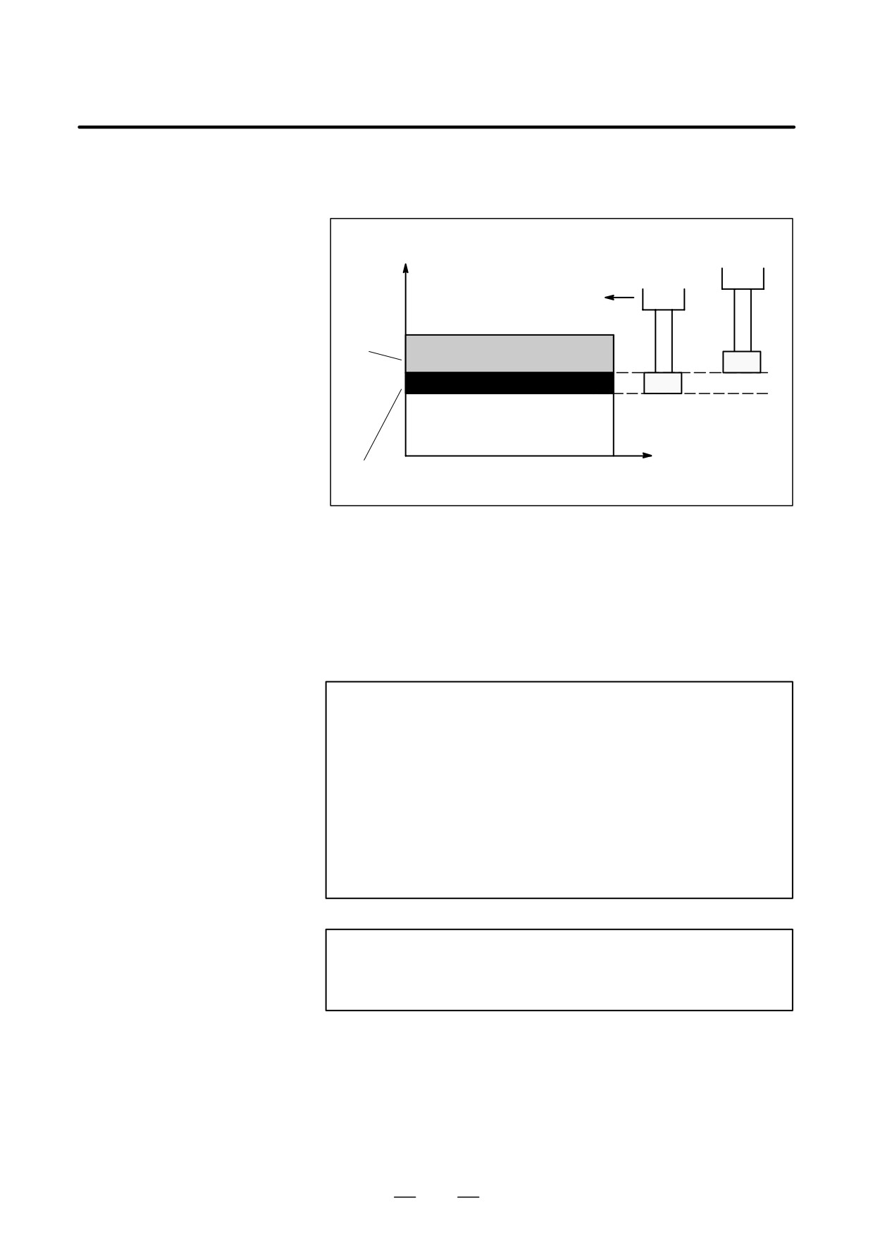
The movement by manual handle operation can be done by overlapping
4.7
it with the movement by automatic operation in the automatic operation
MANUAL HANDLE
mode.
INTERRUPTION
Tool position during
Z
automaticoperation
Tool position after
handleinterruption
Programmed
depth of cut
X
Depth of cut by
handleinterruption
Fig. 4.7 Manual handle interruption
D Handle interruption axis selection signals
For the handle interruption axis selection signals, refer to the manual
supplied by the machine tool builder.
During automatic operation, handle interruption is enabled for an axis
if the handle interruption axis selection signal for that axis is on.
Handle interruption is performed by turning the handle of the manual
pulse generator.
WARNING
The travel distance by handle interruption is determined
according to the amount by which the manual pulse
generator is turned and the handle feed magnification (x1,
x10, xM, xN).
Since this movement is not accelerated or decelerated, it is
very dangerous to use a large magnification value for
handle interruption.
The move amount per scale at x1 magnification is 0.001 mm
(metric output) or 0.0001 inch (inch output).
NOTE
Handle interruption is disabled when the machine is locked
during automatic operation.
501
4. AUTOMATIC OPERATION
OPERATION
B-64124EN/01
Explanations
D Relation with other
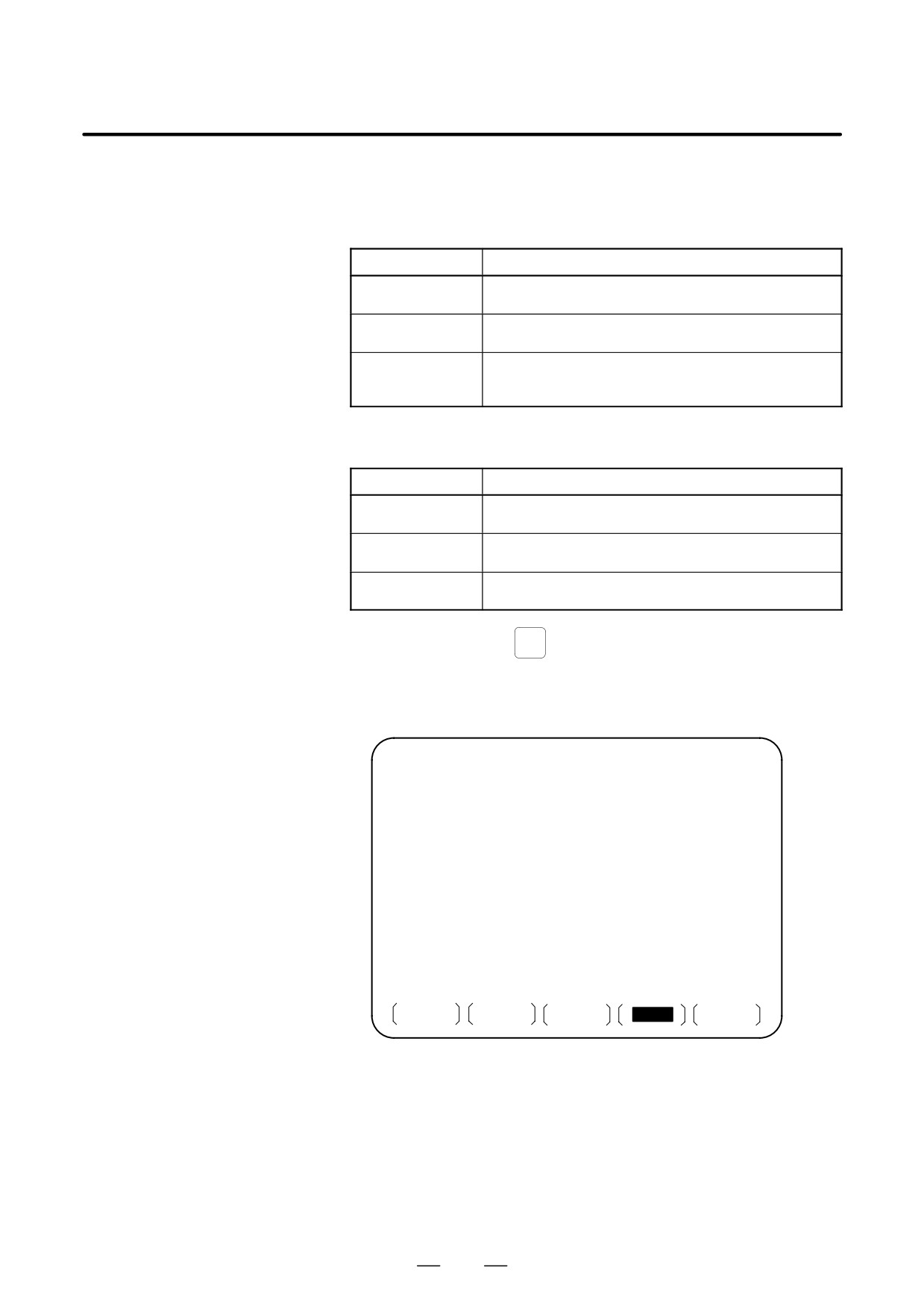
The following table indicates the relation between other functions and the
functions
movement by handle interrupt.
Display
Relation
Machine lock
Machine lock is effective. The tool does not move
even when this signal turns on.
Interlock
Interlock is effective. The tool does not move even
when this signal turns on.
Mirror image
Mirror image is not effective. Interrupt functions on
the plus direction by plus direction command, even if
this signal turns on.
D Position display
The following table shows the relation between various position display
data and the movement by handle interrupt.
Display
Relation
Absolute
Handle interruption does not change absolute
coordinate value
coordinates.
Relative
Handle interruption does not change relative
coordinate value
coordinates.
Machine
Machine coordinates are changed by the travel
coordinate value
distance specified by handle interruption.
D Travel distance display
Press the function key
POS
, then press the chapter selection soft key
[HNDL].
The move amount by the handle interrupt is displayed. The following 4
kinds of data are displayed concurrently.
HANDLE INTERRUPTION
O0000 N02000
(INPUT UNIT)
(OUTPUT UNIT)
X
69.594
X
69.594
Y
137.783
Y
137.783
Z
-61.439
Z
-61.439
(RELATIVE)
(DISTANCE TO GO)
X
0.000
X
0.000
Y
0.000
Y
0.000
Z
0.000
Z
0.000
PART COUNT 287
RUN TIME
1H 12M CYCLE TIME 0H 0M 0S
MDI
* * * *
* * *
* * *
10 : 29 : 51
ABS
REL
ALL
HNDL
(OPRT)
502
B-64124EN/01
OPERATION
4. AUTOMATIC OPERATION
(a) INPUT UNIT
: Handle interrupt move amount in input unit
system
Indicates the travel distance specified by handle
interruption according to the least input
increment.
(b) OUTPUT UNI : Handle interrupt move amount in output unit
system
Indicates the travel distance specified by handle
interruption according to the least command
increment.
(c) RELATIVE
: Position in relative coordinate system
These values have no effect on the travel distance
specified by handle interruption.
(d) DISTANCE TO GO
: The remaining travel distance in the current
block has no effect on the travel distance
specified by handle interruption.
The handle interrupt move amount is cleared when the manual reference
position return ends every axis.
D Independent
By setting bit 2 (IHD) of parameter No. 7100 and bit 5 (HIE) of parameter
acceleration/deceleration
No. 7103 to 1, acceleration/deceleration for manual handle interruption
can always be of the acceleration/deceleration type for manual feed,
without being affected by automatic operation or some other mode.
More specifically, the acceleration/deceleration type set with bit 4 (JGLx)
of parameter No. 1610 and bit 0 (CTLx) of parameter No. 1610 is applied.
Set a time constant with parameter No. 1624, and an FL feedrate with
parameter No. 1625.
503
4. AUTOMATIC OPERATION
OPERATION
B-64124EN/01
4.8
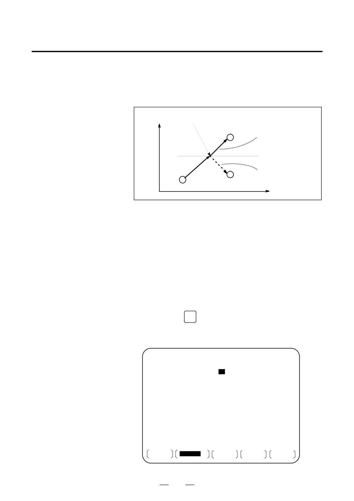
During automatic operation, the mirror image function can be used for
MIRROR IMAGE
movement along an axis. To use this function, set the mirror image switch
to ON on the machine operator’s panel, or set the mirror image setting to
ON from the MDI panel.
Y Y-axis mirror image goes on.
Programmed tool path
Tool path after the mirror
image function is used
Tool
X
Fig. 4.8 Mirror image
Procedure
The following procedure is given as an example. For actual operation,
refer to the manual supplied by the machine tool builder.
1
Press the single block switch to stop automatic operation. When the
mirror image function is used from the begining of operation, this step
is omitted.
2
Press the mirror image switch for the target axis on the machine
operator’s panel.
Alternatively, turn on the mirror image setting by following the steps
below:
2-1 Set the MDI mode.
OFFSET
2-2 Press the
SETTING
function key.
2-3 Press the [SETING] soft key for chapter selection to display the
setting screen.
SETTING (MIRROR IMAGE)
O0020 N00001
MIRROR IMAGE X =
1
(0 : OFF 1 : ON)
MIRROR IMAGE Y = 0 (0 : OFF 1 : ON)
MIRROR IMAGE Z = 0 (0 : OFF 1 : ON)
>_
MEM * * * *
* * *
* * *
14 : 47 : 57
OFFSET
SETING
WORK
(OPRT)
504
B-64124EN/01
OPERATION
4. AUTOMATIC OPERATION
2-4 Move the cursor to the mirror image setting position, then set the
target axis to 1.
3
Enter an automatic operation mode (memory mode or MDI mode),
then press the cycle start button to start automatic operation.
Explanations
D The mirror image function can also be turned on and off by setting bit
0 of parameter 0012 (MIRx) to 1 or 0.
D For the mirror image switches, refer to the manual supplied by the
machine tool builder.
Limitations
The direction of movement during manual operation, the direction of
movement from an intemidiate point to the reference position during
automatic reference position return (G28), the direction of approach
during unidirectional positioning (G60), and the shift direction in a boring
cycle (G76, G87) cannot be reserved.
505
4. AUTOMATIC OPERATION
OPERATION
B-64124EN/01
In cases such as when tool movement along an axis is stopped by feed hold
4.9
during automatic operation so that manual intervention can be used to
MANUAL
replace the tool: When automatic operation is restarted, this function
INTERVENTION AND
returns the tool to the position where manual intervention was started.
To use the conventional program restart function and tool withdrawal and
RETURN
return function, the switches on the operator’s panel must be used in
conjunction with the MDI keys. This function does not require such
operations.
Before this function can be used, MIN (bit 0 of parameter No. 7001) must
be set to 1.
Explanations
D Manual absolute on/off
In manual absolute off mode, the tool does not return to the stop position,
but instead operates according to the manual absolute on/off function.
D Override
For the return operation, the dry run feedrate is used, and the jog feedrate
override function is enabled.
D Return operation
Return operation is performed according to positioning based on
nonlinear interpolation.
D Single block
If the single block stop switch is on during return operation, the tool stops
at the stop position and restarts movement when the cycle start switch is
pressed.
D Cancellation
If a reset occurs or an alarm is issued during manual intervention or the
return operation, this function is cancelled.
D MDI mode
This function can be used in the MDI mode as well.
Limitations
D Enabling and disabling
This function is enabled only when the automatic operation hold LED is
manual intervention and
on. When there is no travel distance remaining, this function has no effect
return
even if a feed hold stop is performed with the automatic operation hold
signal *SP (bit 5 of G008).
D Offset
When the tool is replaced using manual intervention for a reason such as
damage, the tool movement cannot be restarted by a changed offset in the
middle of the interrupted block.
D Machine lock, mirror
When performing manual intervention, never use the machine lock,
image, and scaling
mirror image, or scaling functions.
506
B-64124EN/01
OPERATION
4. AUTOMATIC OPERATION
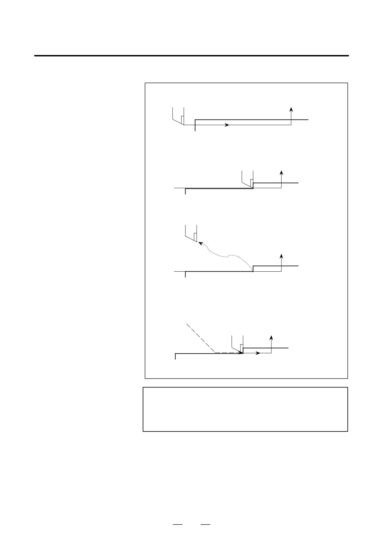
Example
1. The N1 block cuts a workpiece
Tool
N2
Block start point
N1
2. The tool is stopped by pressing the feed hold switch in
the middle of the N1 block (point A).
N2
N1 Point A
3. After retracting the tool manually to point B, tool movement is restarted.
Point B
Manual
intervention
N2
N1 Point A
4. After automatic return to point A at the dry run feedrate, the remaining
move command of the N1 block is executed.
B
N2
N1 Point A
WARNING
When performing manual intervention, pay particular
attention of machining and the shape of the workpiece so
that the machine and tool are not damaged.
507
4. AUTOMATIC OPERATION
OPERATION
B-64124EN/01
4.10
DNC OPERATION
WITH MEMORY
CARD
4.10.1
“DNC operation with Memory Card” is a function that it is possible to
perform machining with executing the program in the memory card,
Specification
which is assembled to the memory card interface, where is the left side
of the screen.
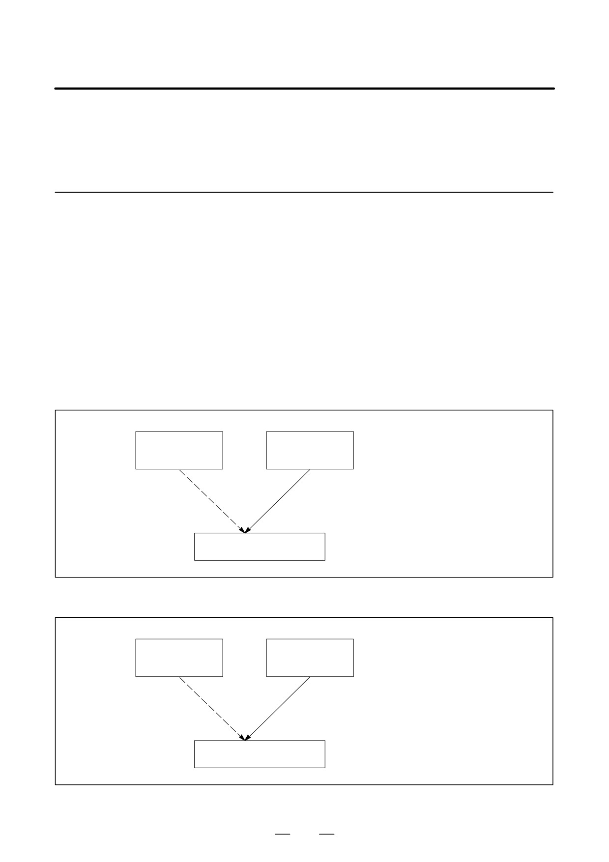
There are two methods to use this function as follows.
(a) By starting automatic operation
(cycle start) during the DNC
operation mode (RMT), it is possible to perform machining (DNC
operation) while a program is being read from a memory card, as by
using the external input/output unit such as a floppy cassette and so on.
(Fig. 4.10.1 (a))
(b) It is possible to read sub-programs written in the memory card and
execute them by the command Subprogram call (M198). (Fig. 4.10.1
(b))
It is possible to do the DNC
Memory in CNC
Memory Card
operation with Memory card
(Program)
(Program)
instead of the normal memory
operation by memory in the CNC.
Normal Memory
DNC operation
operation by
with Memory
memory in the
card
CNC
Execution of programs
Fig. 4.10.1 (a)
It is possible to execute the
Memory in CNC
Memory Card
subprogram in the memory card
(Program)
(Sub Program)
during memory operation.
Normal Memory
Subprogram
operation by memory
Call (M198)
in the CNC
Execution of programs
Fig. 4.10.1 (b)
508
B-64124EN/01
OPERATION
4. AUTOMATIC OPERATION
NOTE
To use this function, it is necessary to set the parameter of
No.20 to 4 by setting screen.
No.20 [I/O CHANEL: Setting to select an input/output unit]
Setting value is
4.: It means using the memory card
interface.
4.10.2
Operations
4.10.2.1
DNC Operation
Procedure
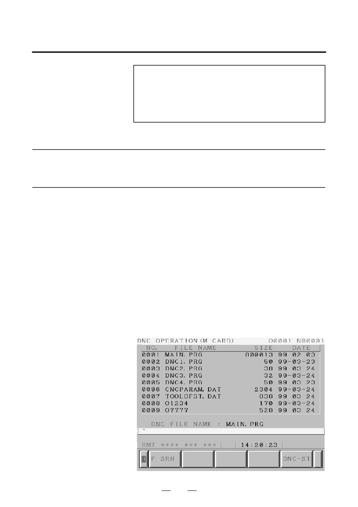
Please set the parameter of No.0020 to 4 in the setting screen in advance.
(1) Change to RMT mode.
(2) Push [PROG] function key.
(3) Push [ > ] soft key (continuance menu).
(4) When [DNC-CD] soft key is pushed, the following screen is
displayed.
(5) The screen can be scrolled by page key. An arbitrary file number is
input, and [F SRH] soft key is pushed. Then the arbitrary file name
is displayed at the top of DNC operation (memory card) screen.
(6) When the file number that is executed is input and the [DNC-ST] soft
key is pushed, the file name that is selected is set to DNC FILE.
(7) When the cycle start is done, the program that is selected is executed.
509
4. AUTOMATIC OPERATION
OPERATION
B-64124EN/01
4.10.2.2
When the following block in a program in CNC memory is executed, a
subprogram file in memory card is called.
Subprogram Call (M198)
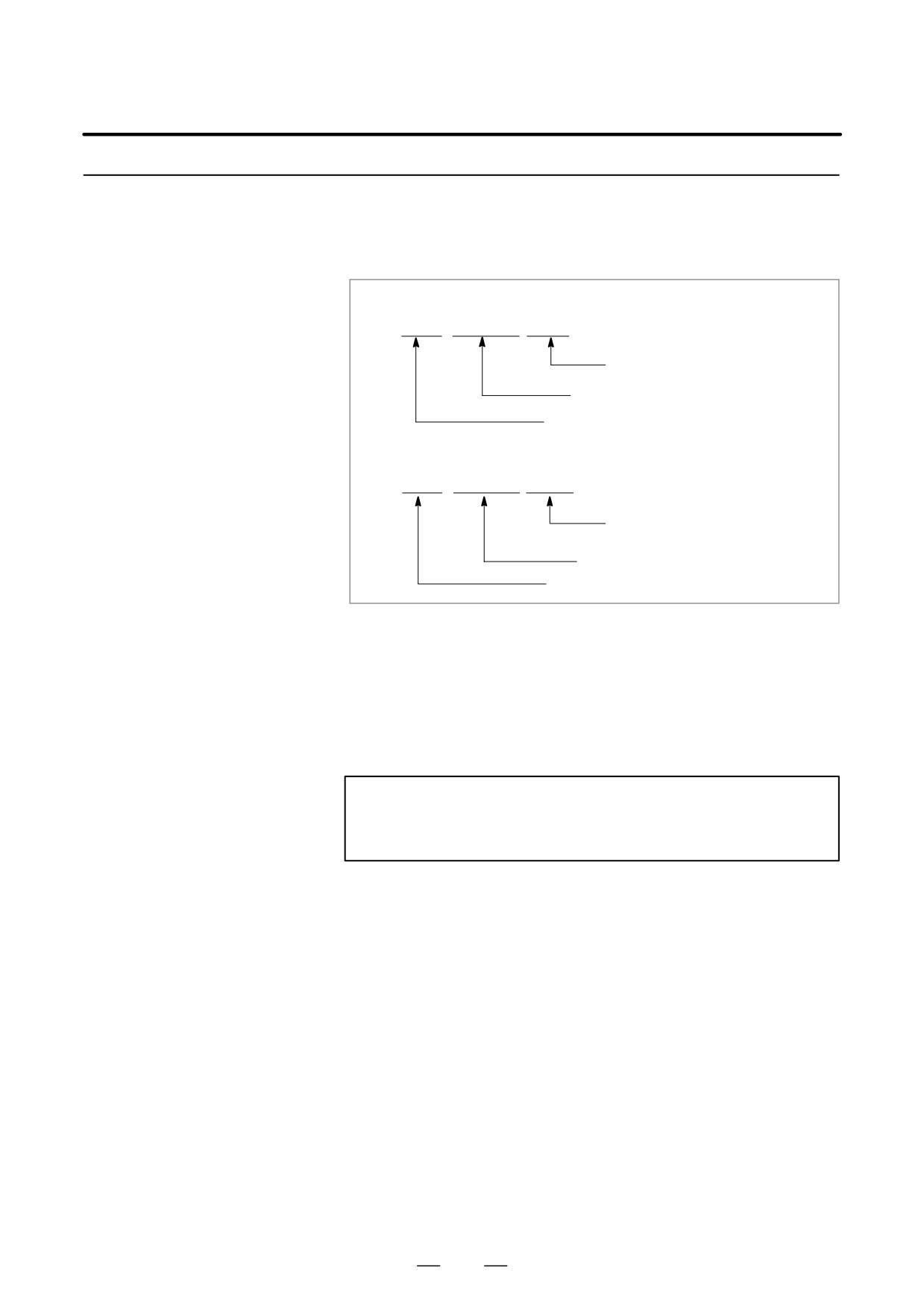
Format
1. Normal format
M198 Pffff ∆∆∆∆ ;
File number for a file in
the memory card
Number of repetition
Memory card call instruction
2. FS15 tape format
M198 Pffff L∆∆∆∆ ;
File number of repetition
File number for a file in the
memory card
Memory card call instruction
Explanation
Both format 1 and 2 can be used. A different M code can be used for a
subprogram call depending on the setting of parameter No. 6030. In this
case, M198 is executed as a normal M code. The file number is specified
at address P. If the SBP (bit 2) of parameter No. 3404 is set to 1, a program
number can be specified. When a file number is specified at address P,
Fxxxx is indicated instead of Oxxxx.
NOTE
Please set the parameter of No. 0020 to 4 in the setting
screen in advance.
510
B-64124EN/01
OPERATION
4. AUTOMATIC OPERATION
4.10.3
(1) The memory card can not be accessed, such as display of memory card
list and so on, during the DNC operation with memory card.
Limitation and Notes
(2) The selection of DNC operation file that is set at DNC OPERATION
screen is cleared by the power supply turn off and on. After the power
supply is turned on again, it is necessary to select the DNC operation
file again.
(3) Please do not pull out and insert memory card during the DNC
operation with memory card.
(4) It is not possible to call a program in the memory card from the DNC
operation program.
(5) When this function is used, secure the memory card by following the
procedure described later, to prevent the card from becoming
disconnected or poorly connected due to vibration during operation or
for some other reason.
4.10.4
#7
#6
#5
#4
#3
#2
#1
#0
Parameter
0138
DNM
[Data type] Bit
#7 (DNM) The DNC operation with memory card function is
0 : disable.
1 : enable.
4.10.5
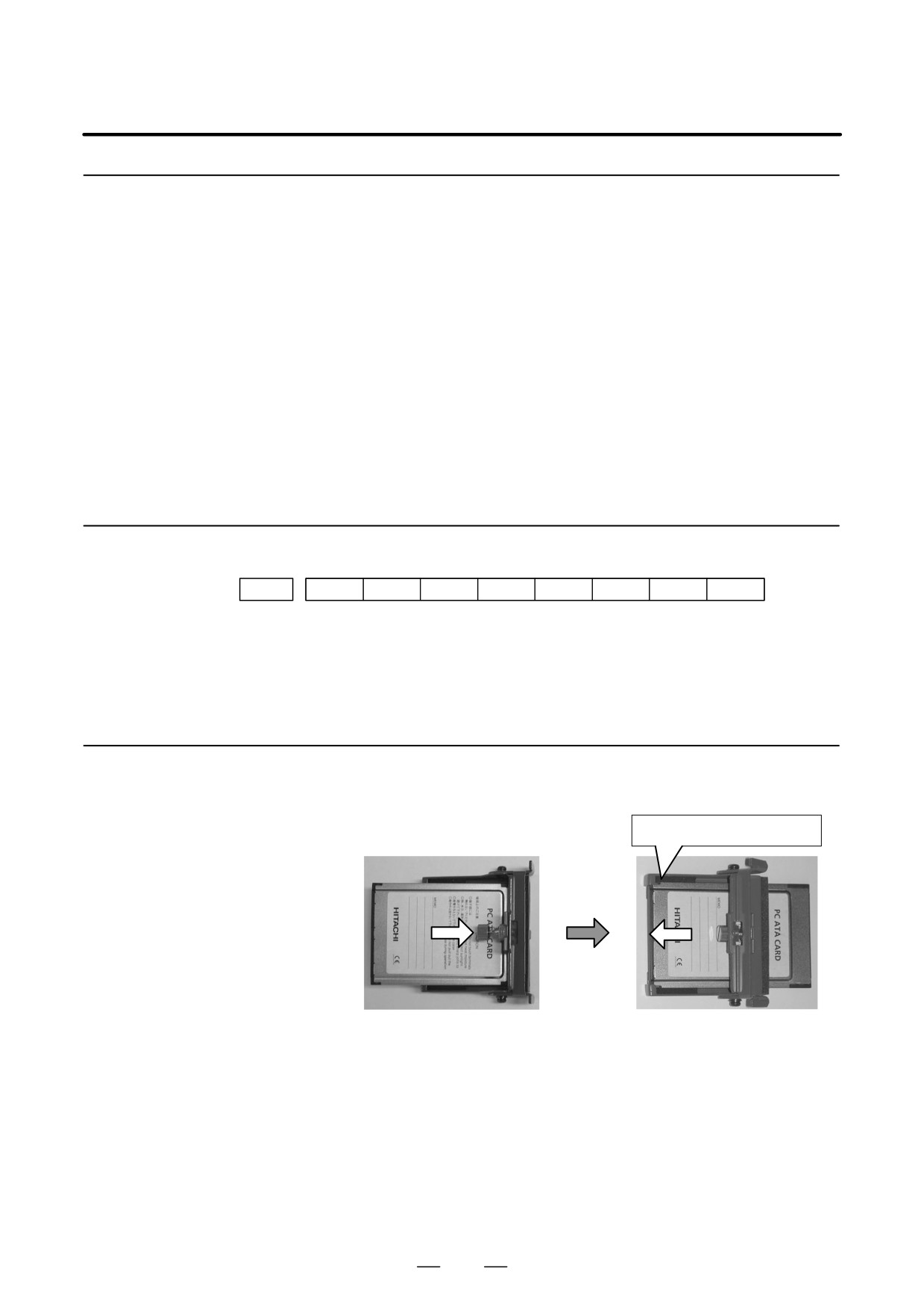
Follow the procedure below to fix the memory card.
Procedure for Fixing
1. Inserting the memory card into the fixing bracket
the Memory Card
Fix the card at this point.
Insert the memory card into the
Fix the memory card to the fixing
fixing bracket in the direction
bracket.
indicated by the arrow.
511
4. AUTOMATIC OPERATION
OPERATION
B-64124EN/01
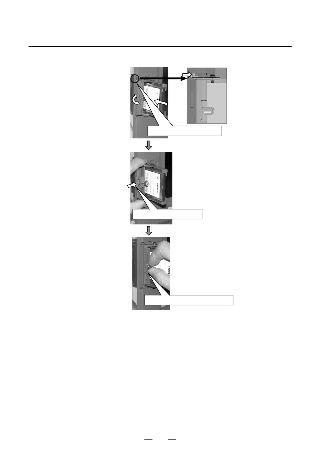
2. Inserting the card into the PCMCIA port.
Loosen the screw of the
fixing bracket and insert
the memory card into the
PCMCIA port with the
claw of the fixing bracket
raised.
Align the claw with the groove.
Align the claw of the fixing bracket
with the groove of the PCMCIA port
and then push the bracket in the
direction indicated by the arrow.
Push the bracket to the right.
Tighten the screw of the bracket
to fix the memory card.
Fix the card by tightening the screw.
512
B-64124EN/01
OPERATION
5. TEST OPERATION
TEST OPERATION
5
The following functions are used to check before actual machining
whether the machine operates as specified by the created program.
5.1
MACHINE LOCK AND AUXILIARY FUNCTION LOCK
5.2
FEEDRATE OVERRIDE
5.3
RAPID TRAVERSE OVERRIDE
5.4
DRY RUN
5.5
SINGLE BLOCK
513
5. TEST OPERATION
OPERATION
B-64124EN/01
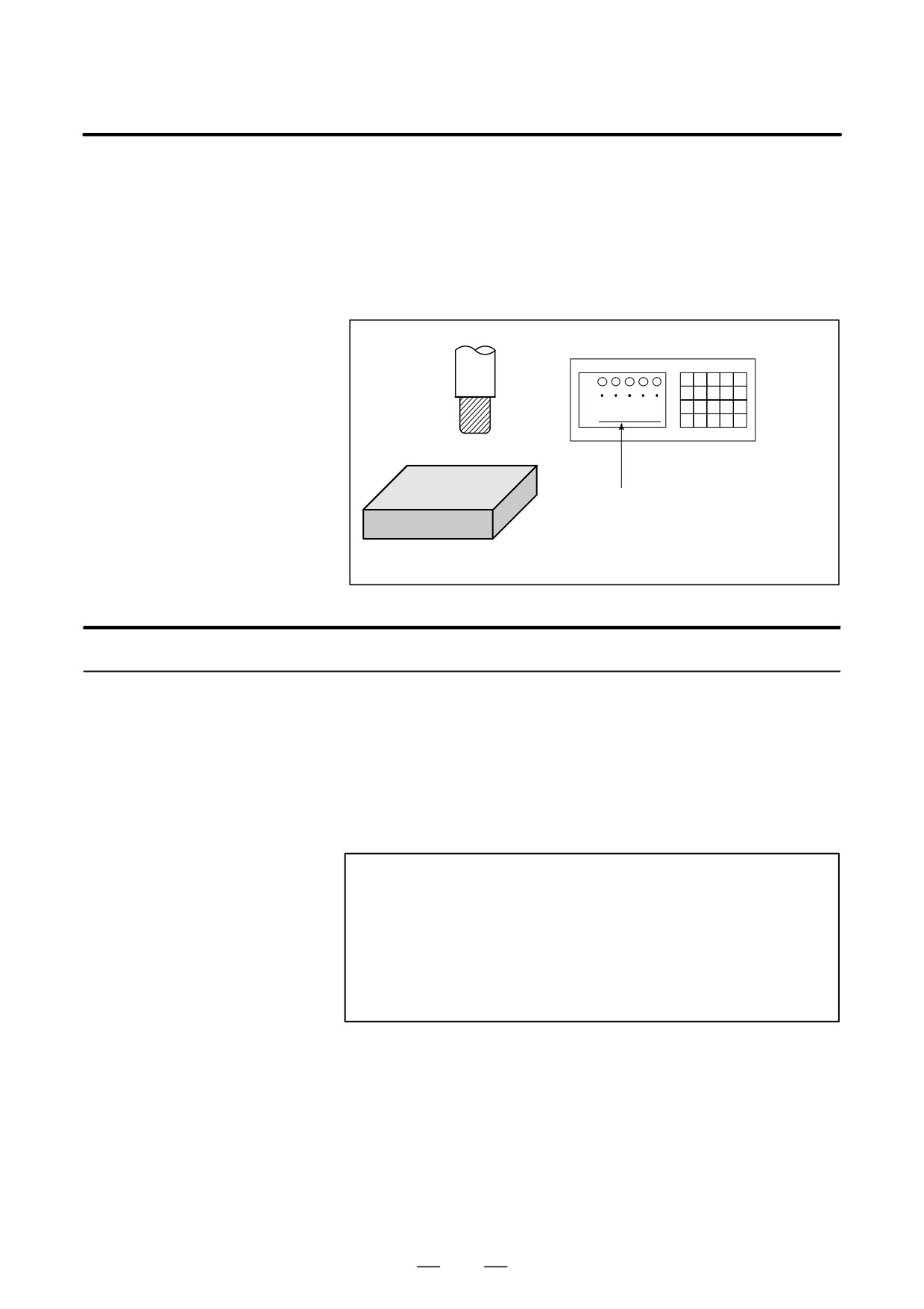
To display the change in the position without moving the tool, use
5.1
machine lock.
MACHINE LOCK AND
There are two types of machine lock: all-axis machine lock, which stops
AUXILIARY
the movement along all axes, and specified-axis machine lock, which
stops the movement along specified axes only. In addition, auxiliary
FUNCTION LOCK
function lock, which disables M, S, and T commands, is available for
checking a program together with machine lock.
MDI
X
Y
Tool
Z
Workpiece
The tool does not move but the
position along each axis changes
on the display.
Fig. 5.1 Machine lock
Procedure for Machine Lock and Auxiliary Function Lock
D Machine Lock
Press the machine lock switch on the operator’s panel. The tool does not
move but the position along each axis changes on the display as if the tool
were moving.
Some machines have a machine lock switch for each axis. On such
machines, press the machine lock switches for the axes along which the
tool is to be stopped. Refer to the appropriate manual provided by the
machine tool builder for machine lock.
WARNING
The positional relationship between the workpiece
coordinates and machine coordinates may differ before and
after automatic operation using machine lock. In such a
case, specify the workpiece coordinate system by using a
coordinate setting command or by performing manual
reference position return.
D Auxiliary Function Lock
Press the auxiliary function lock switch on the operator’s panel. M, S, T
and B codes are disabled and not executed. Refer to the appropriate
manual provided by the machine tool builder for auxiliary function lock.
514
B-64124EN/01
OPERATION
5. TEST OPERATION
Restrictions
D M, S, T, B command by
M, S, T and B commands are executed in the machine lock state.
only machine lock
D Reference position
When a G27, G28, or G30 command is issued in the machine lock state,
return under Machine
the command is accepted but the tool does not move to the reference
Lock
position and the reference position return LED does not go on.
D M codes not locked by
M00, M01, M02, M30, M98, M99, and M198 (Subprogram call)
auxiliary function lock
commands are executed even in the auxiliary function lock state. M codes
for calling a subprogram (parameters No. 6071 to 6079) and those for
calling a custom macro (parameter No. 6080 to 6089) are also executed.
515
5. TEST OPERATION
OPERATION
B-64124EN/01
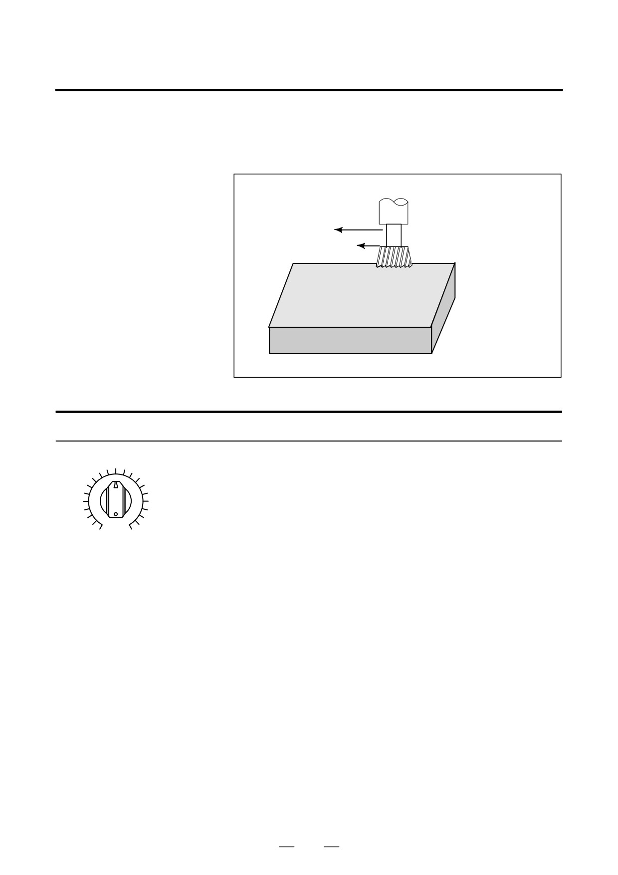
A programmed feedrate can be reduced or increased by a percentage (%)
5.2
selected by the override dial.This feature is used to check a program.
FEEDRATE
For example, when a feedrate of 100 mm/min is specified in the program,
OVERRIDE
setting the override dial to 50% moves the tool at 50 mm/min.
Feedrate 100 mm/min
Tool
(Specified by programmed)
Check the machining
by altering the feedrate
Feedrate 50 mm/min after
from the value speci-
feedrate override
fied in the program.
Workpiece
Fig. 5.2 Feedrate override
Procedure for Feedrate Override
Set the feedrate override dial to the desired percentage (%) on the machine
operator’s panel, before or during automatic operation.
On some machines, the same dial is used for the feedrate override dial and
jog feedrate dial. Refer to the appropriate manual provided by the
machine tool builder for feedrate override.
0
200
JOG FEED RATE OVERRIDE
Restrictions
D Override Range
The override that can be specified ranges from 0 to 254%. For individual
machines, the range depends on the specifications of the machine tool
builder.
D Override during thread
During threading, the override is ignored and the feedrate remains as
specified by program.
516
B-64124EN/01
OPERATION
5. TEST OPERATION
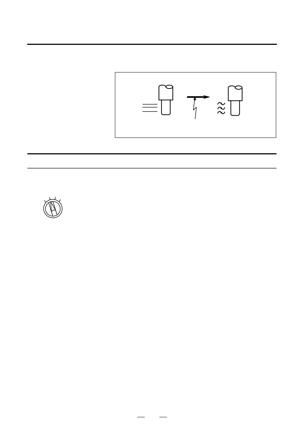
An override of four steps (F0, 25%, 50%, and 100%) can be applied to the
5.3
rapid traverse rate. F0 is set by a parameter (No. 1421).
RAPID TRAVERSE
OVERRIDE
ÇÇ
ÇÇ
ÇÇ
ÇÇ
ÇÇ
ÇÇ
Rapid traverse Override
5m/min
rate10m/min
50%
Fig. 5.3 Rapid traverse override
Rapid Traverse Override
Procedure
Select one of the four feedrates with the rapid traverse override switch
during rapid traverse. Refer to the appropriate manual provided by the
25
50
machine tool builder for rapid traverse override.
LOW
100
Rapid traverse override
Explanation
The following types of rapid traverse are available. Rapid traverse
override can be applied for each of them.
1) Rapid traverse by G00
2) Rapid traverse during a canned cycle
3) Rapid traverse in G27, G28, G29, G30, G53
4) Manual rapid traverse
5) Rapid traverse of manual reference position return
517
5. TEST OPERATION
OPERATION
B-64124EN/01
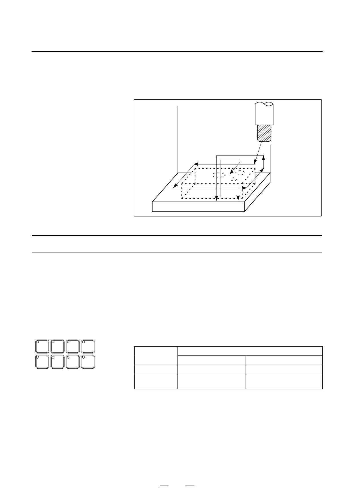
The tool is moved at the feedrate specified by a parameter regardless of
5.4
the feedrate specified in the program. This function is used for checking
DRY RUN
the movement of the tool under the state taht the workpiece is removed
from the table.
Tool
Table
Fig. 5.4 Dry run
Procedure for Dry Run
Procedure
Press the dry run switch on the machine operator’s panel during automatic
operation.
The tool moves at the feedrate specified in a parameter. The rapid traverse
switch can also be used for changing the feedrate.
Refer to the appropriate manual provided by the machine tool builder for
dry run.
Explanation
D Dry run feedrate
The dry run feedrate changes as shown in the table below according to the
rapid traverse switch and parameters.
SINGLE
OPT
BLOCK
MC
BLOCK
STOP
SKIP
LOCK
Rapid traverse
Program command
button
DRY
MST
WORK
Rapid traverse
Feed
RUN
LOCK
LIGHT
ON
Rapid traverse rate
Dry run feedrate Max.JV *2)
OFF
Dry run speed JV,or
Dry run feedrate JV
rapid traverse rate *1)
*2)
Max. cutting feedrate
Setting by parameter No.1422
Rapid traverse rate
Setting by parameter No.1420
Dry run feedrate
Setting by parameter No.1410
JV: Jog feedrate override
*1) Dry run feedrate x JV when parameter RDR (bit 6 of No. 1401) is
1. Rapid traverse rate when parameter RDR is 0.
*2) Clamped to the maximum cutting feedrate
JVmax: Maximum value of jog feedrate override
518
B-64124EN/01
OPERATION
5. TEST OPERATION
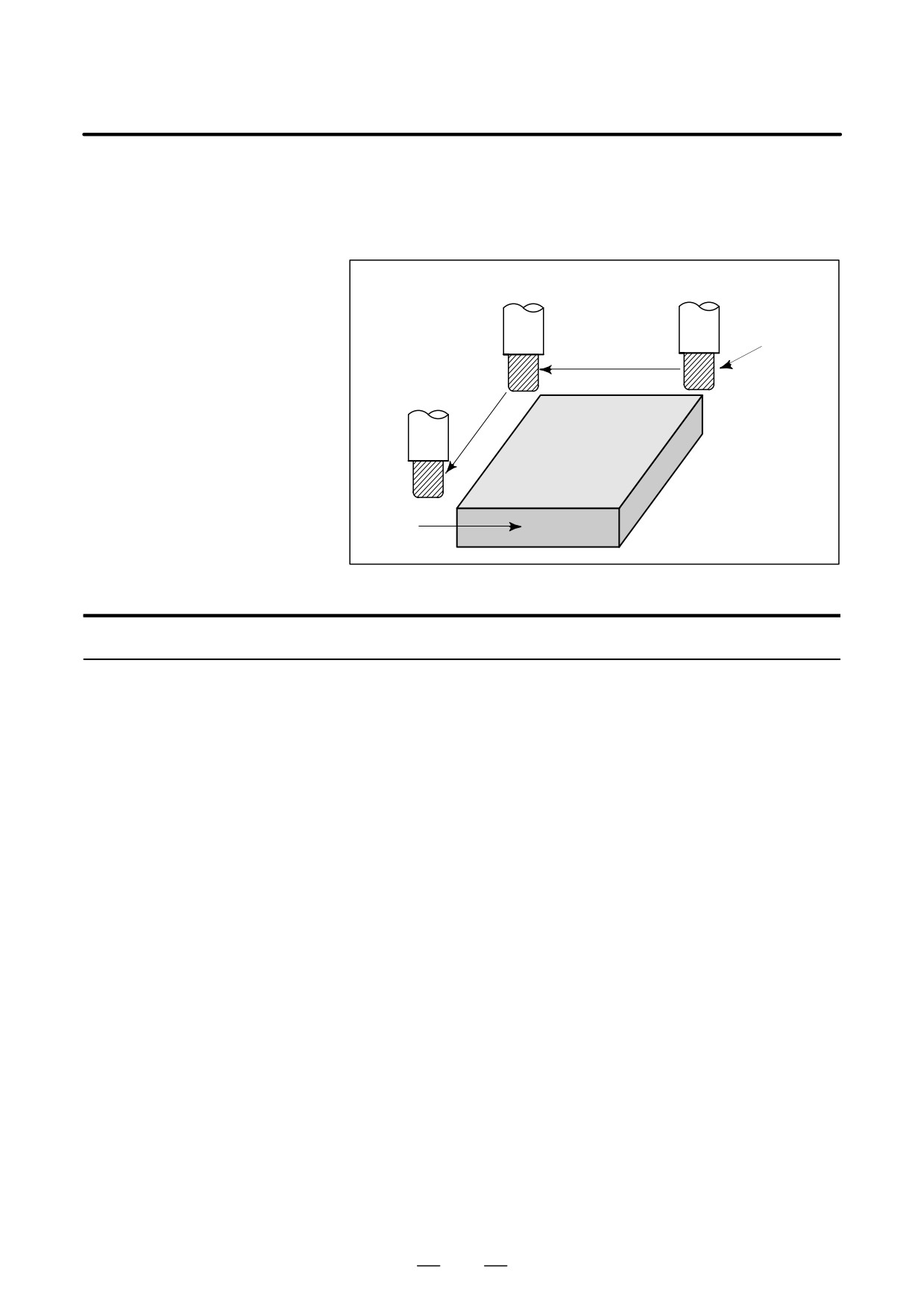
Pressing the single block switch starts the single block mode. When the
5.5
cycle start button is pressed in the single block mode, the tool stops after
SINGLE BLOCK
a single block in the program is executed. Check the program in the single
block mode by executing the program block by block.
Cycle start
Cycle start
Tool
Cycle start
Stop
Stop
Workpiece
Stop
Fig. 5.5 (a) Single block
Procedure for Single block
Procedure
1
Press the single block switch on the machine operator’s panel. The
execution of the program is stopped after the current block is
executed.
2
Press the cycle start button to execute the next block. The tool stops
after the block is executed.
Refer to the appropriate manual provided by the machine tool builder
for single block execution.
519
5. TEST OPERATION
OPERATION
B-64124EN/01
Explanation
D Reference position
If G28 to G30 are issued, the single block function is effective at the
return and single block
intermediate point.
D Single block during a
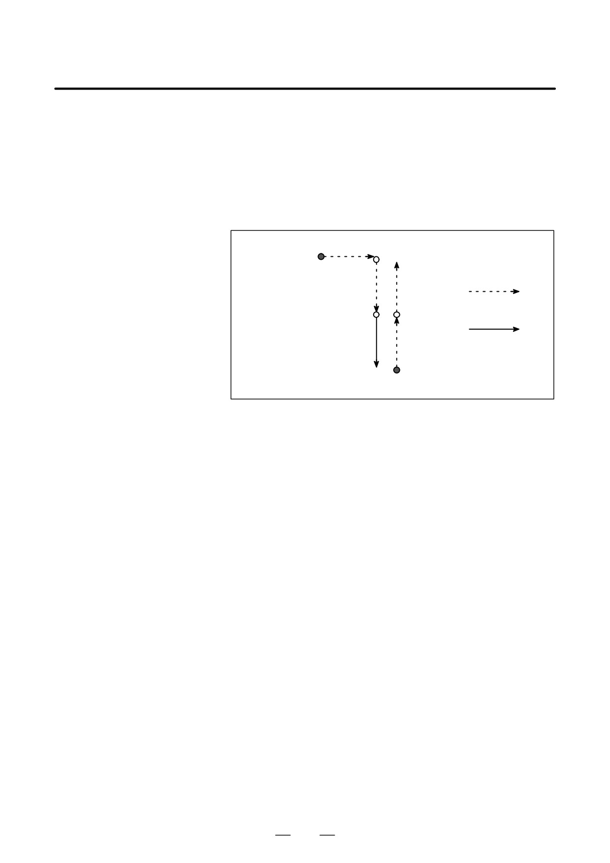
In a canned cycle, the single block stop points are the end of
,
, and
canned cycle
shown below. When the single block stop is made after the point
or
, the feed hold LED lights.
Rapid traverse
Feed
Fig. 5.5 (b) Single block during canned cycle
D Subprogram call and
Single block stop is not performed in a block containing M98P_;. M99;
single block
or G65.
However, single block stop is even performed in a block with M98P_ or
M99 command, if the block contains an address other than O, N, P, L.
520
B-64124EN/01
OPERATION
6. SAFETY FUNCTIONS
SAFETY FUNCTIONS
6
To immediately stop the machine for safety, press the Emergency stop
button. To prevent the tool from exceeding the stroke ends, Overtravel
check and Stroke check are available. This chapter describes emergency
stop., overtravel check, and stroke check.
521

6. SAFETY FUNCTIONS
OPERATION
B-64124EN/01
If you press Emergency Stop button on the machine operator’s panel, the
6.1
machine movement stops in a moment.
EMERGENCY STOP
Red
EMERGENCY STOP
Fig. 6.1 Emergency stop
This button is locked when it is pressed. Although it varies with the
machine tool builder, the button can usually be unlocked by twisting it.
Explanation
EMERGENCY STOP interrupts the current to the motor.
Causes of trouble must be removed before the button is released.
522