FANUC Series 0i-MC. OPERATOR’S MANUAL - page 10
B-64124EN/01
PROGRAMMING
14. COMPENSATION FUNCTION
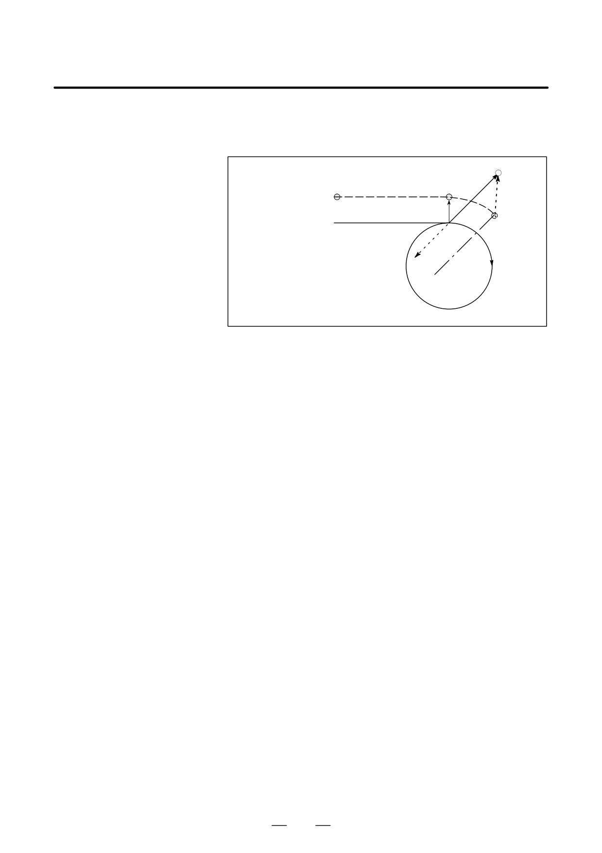
The length of the tool center In the example shown below, the tool does not trace the circle more than
path larger than the circumfer- once. It moves along the arc from P1 to P2. The interference check
ence of a circle
function described in II-14.5.5 may raise an alarm.
Tool center path
P1
P2
Programmed path
N7
N5
N6
(I, J)
(G41)
N5 G01 G91 X100.0 ;
N6 G02 J-60.0 ;
N7 G40 G01 X50.0 Y50.0 I-10.0 J-10.0 ;
To make the tool trace a circle more than once, program two or more arcs.
253
14. COMPENSATION FUNCTION
PROGRAMMING
B-64124EN/01
14.5.5
Tool overcutting is called interference. The interference check function
checks for tool overcutting in advance. However, all interference cannot
Interference Check
be checked by this function. The interference check is performed even if
overcutting does not occur.
Explanations
D Criteria for detecting
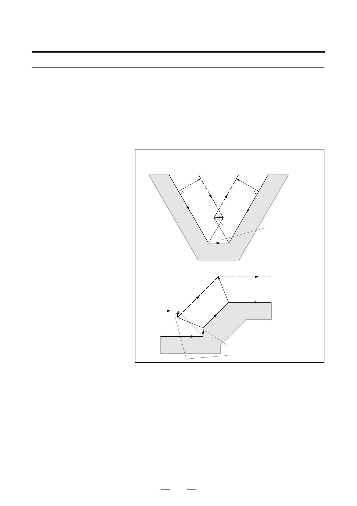
(1) The direction of the tool path is different from that of the programmed
interference
path (from 90 degrees to 270 degrees between these paths).
Tool center path
Programmed path
The directions of
these two paths are
different (180°).
Tool center path
Programmed path
The directions of
these two paths are
different (180°).
254
B-64124EN/01
PROGRAMMING
14. COMPENSATION FUNCTION
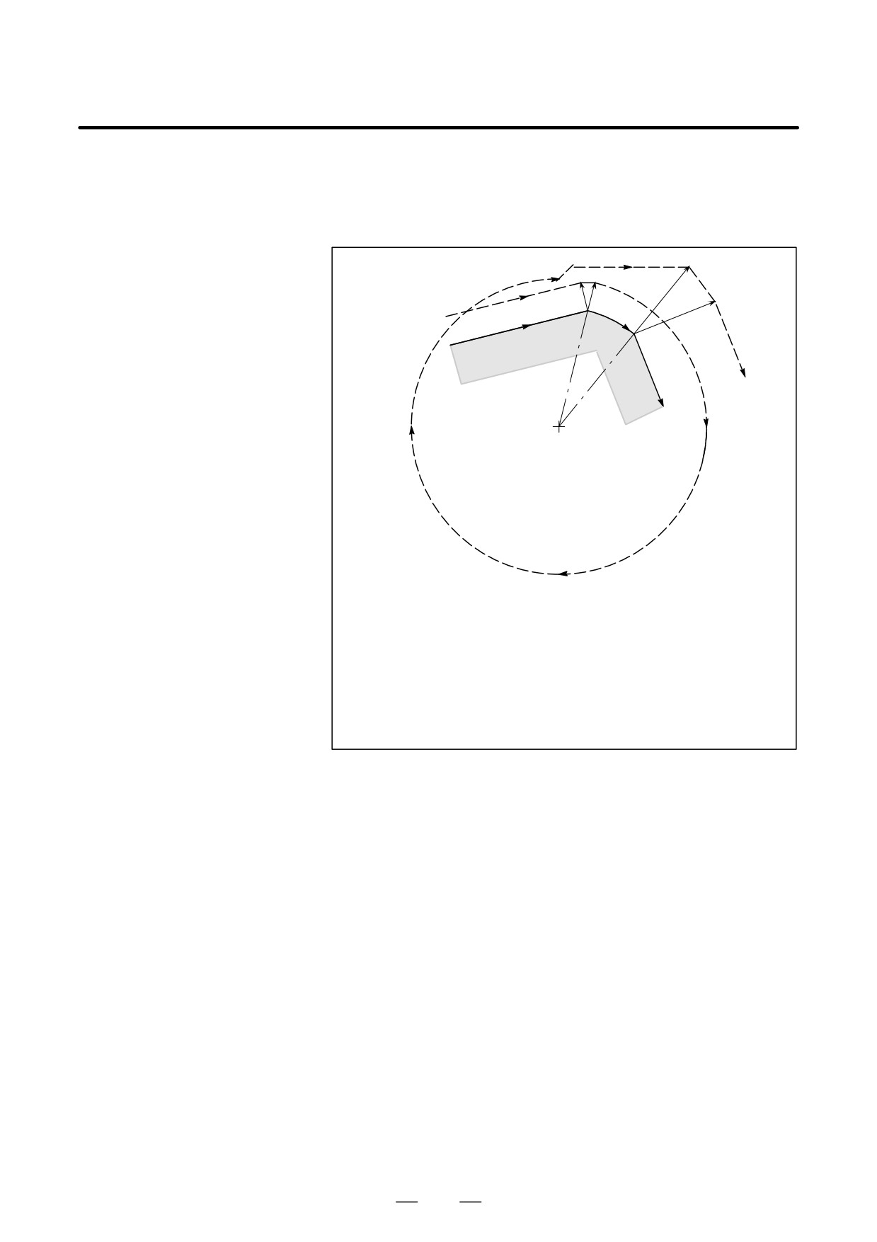
(2) In addition to the condition (1), the angle between the start point and
end point on the tool center path is quite different from that between
the start point and end point on the programmed path in circular
machining(more than 180 degrees).
r2
Tool center path
r1
N5
N6
Programmed path
N7
Center
(G41)
N5 G01 G91 X800.0 Y200.0 D1 ;
N6 G02 X320.0 Y-160.0 I-200.0 J-800.0 D2 ;
N7 G01 X200.0 Y-500.0 ;
(Tool compensation value corresponding to D1 : r1 = 200.0)
(Tool compensation value corresponding to D2 : r2 = 600.0)
In the above example, the arc in block N6 is placed in the one quadrant.
But after cutter compensation, the arc is placed in the four quadrants.
255
14. COMPENSATION FUNCTION
PROGRAMMING
B-64124EN/01
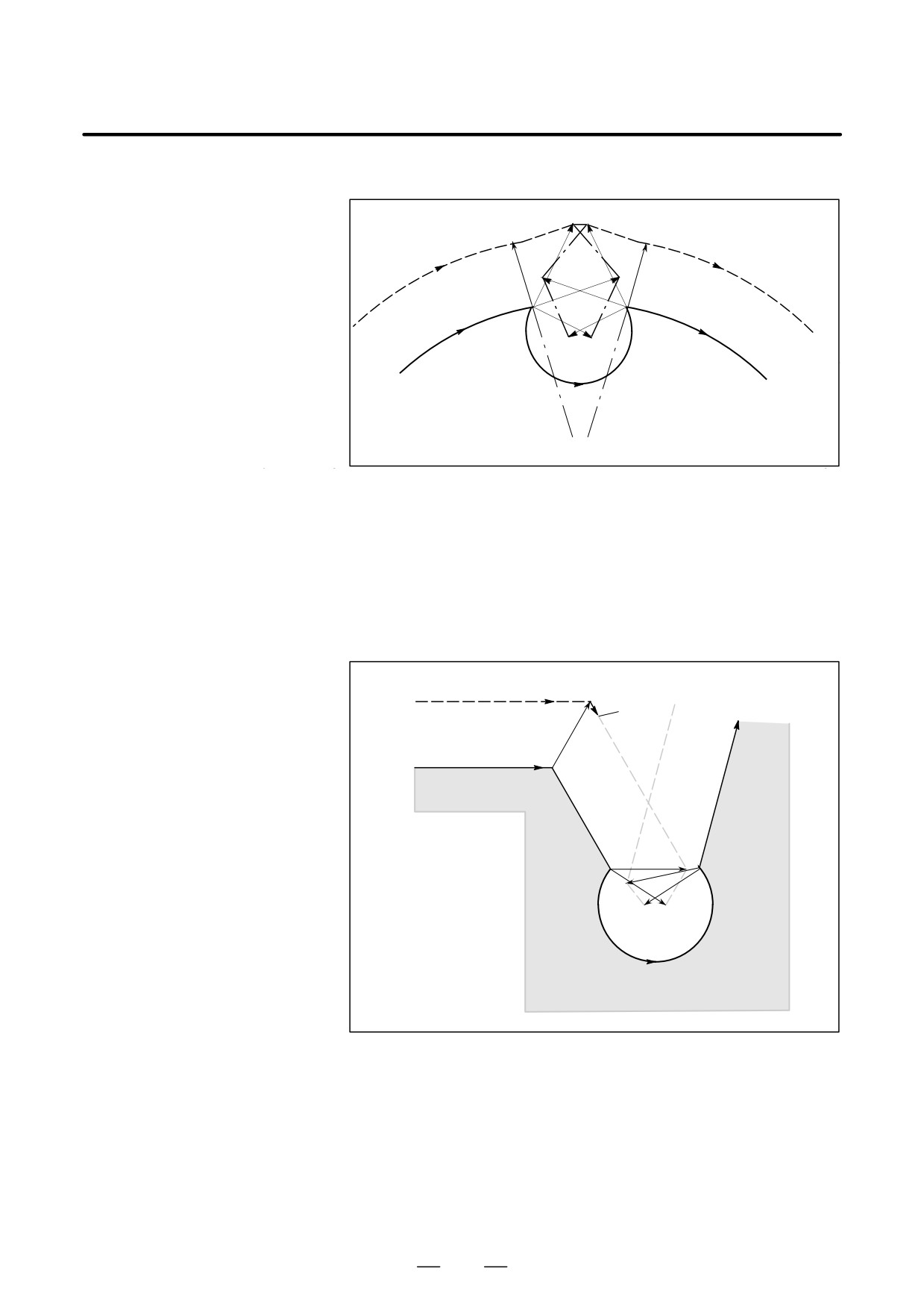
D Correction of
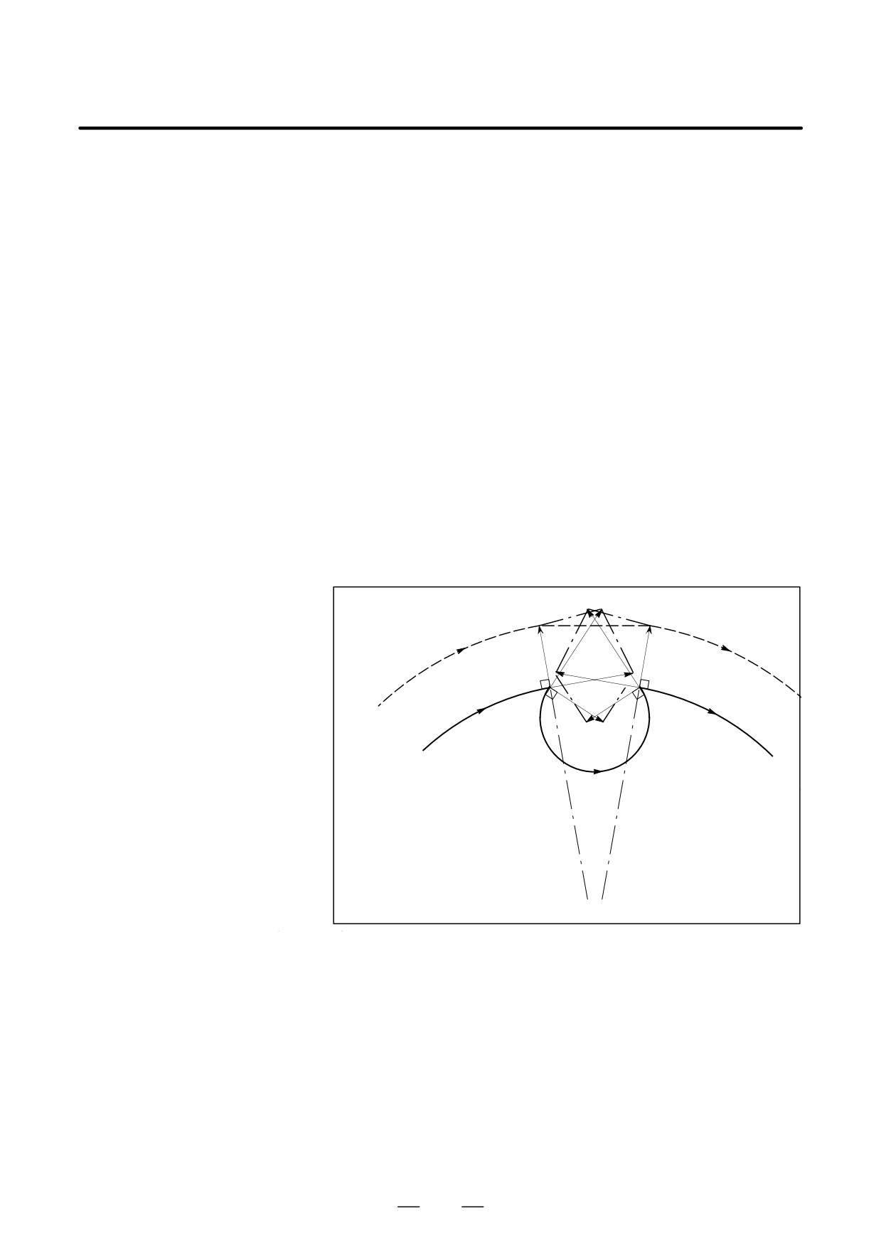
(1) Removal of the vector causing the interference
interference in advance
When cutter compensation is performed for blocks A, B and C and
vectors V1, V2, V3 and V4 between blocks A and B, and V5, V6, V7
and V8 between B and C are produced, the nearest vectors are checked
first. If interference occurs, they are ignored. But if the vectors to be
ignored due to interference are the last vectors at the corner, they
cannot be ignored.
Check between vectors V4 and V5
Interference --- V4 and V5 are ignored.
Check between V3 and V6
Interference --- V3 and V6 are ignored
Check between V2 and V7
Interference --- V2 and V7 are Ignored
Check between V1 and V8
Interference ----- V1 and V8 are cannot be ignored
If while checking, a vector without interference is detected,
subsequent vectors are not checked. If block B is a circular
movement, a linear movement is produced if the vectors are
interfered.
(Example 1) The tool moves linearly from V1 to V8
V7
V2
V1
V8
Tool
C
center path
V3
C
r
V6
r
Programmed
A
C
V5
V4
path
B
V4, V5 : Interference
V3, V6 : Interference
V2, V7 : Interference
V1, V8 : No Interference
O1
O2
256
B-64124EN/01
PROGRAMMING
14. COMPENSATION FUNCTION
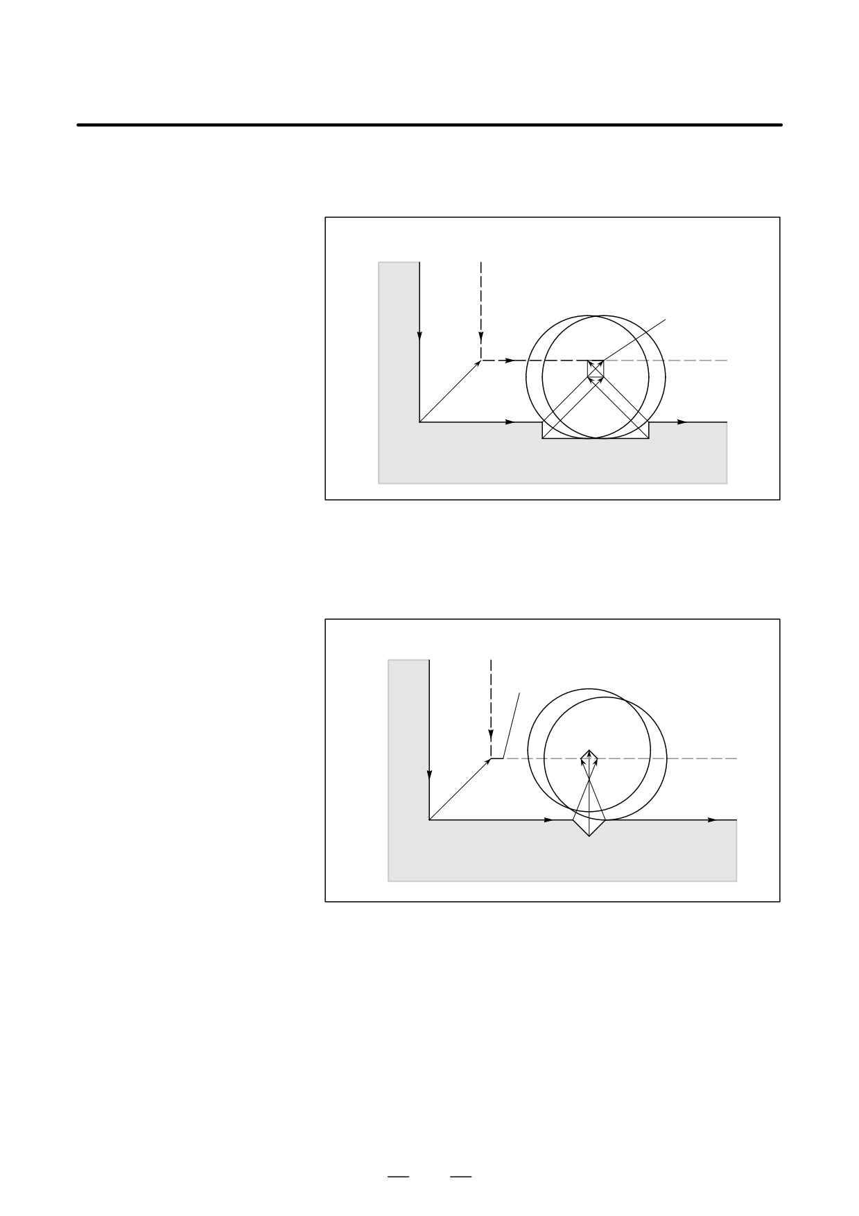
(Example 2) The tool moves linearly from V1, V2, V7, to V8
V2
V7
V1
V8
Tool center
path
C
V6
V3
C
r
r
A
C
V5
V4
Programmed path
B
V4, V5 : Interference
V3, V6
: Interference
O1
O2
V2, V7 : No Interference
(2) If the interference occurs after correction (1), the tool is stopped with
an alarm.
If the interference occurs after correction (1) or if there are only one
pair of vectors from the beginning of checking and the vectors
interfere, the P/S alarm (No.41) is displayed and the tool is stopped
immediately after execution of the preceding block. If the block is
executed by the single block operation, the tool is stopped at the end
of the block.
Tool center
path
Stopped
Programmed path
C
A
V1
V6
V5
V2
B
After ignoring vectors V2 and V5 because of interference, interference
also occurs between vectors V1 and V6. The alarm is displayed and
the tool is stopped.
257
14. COMPENSATION FUNCTION
PROGRAMMING
B-64124EN/01
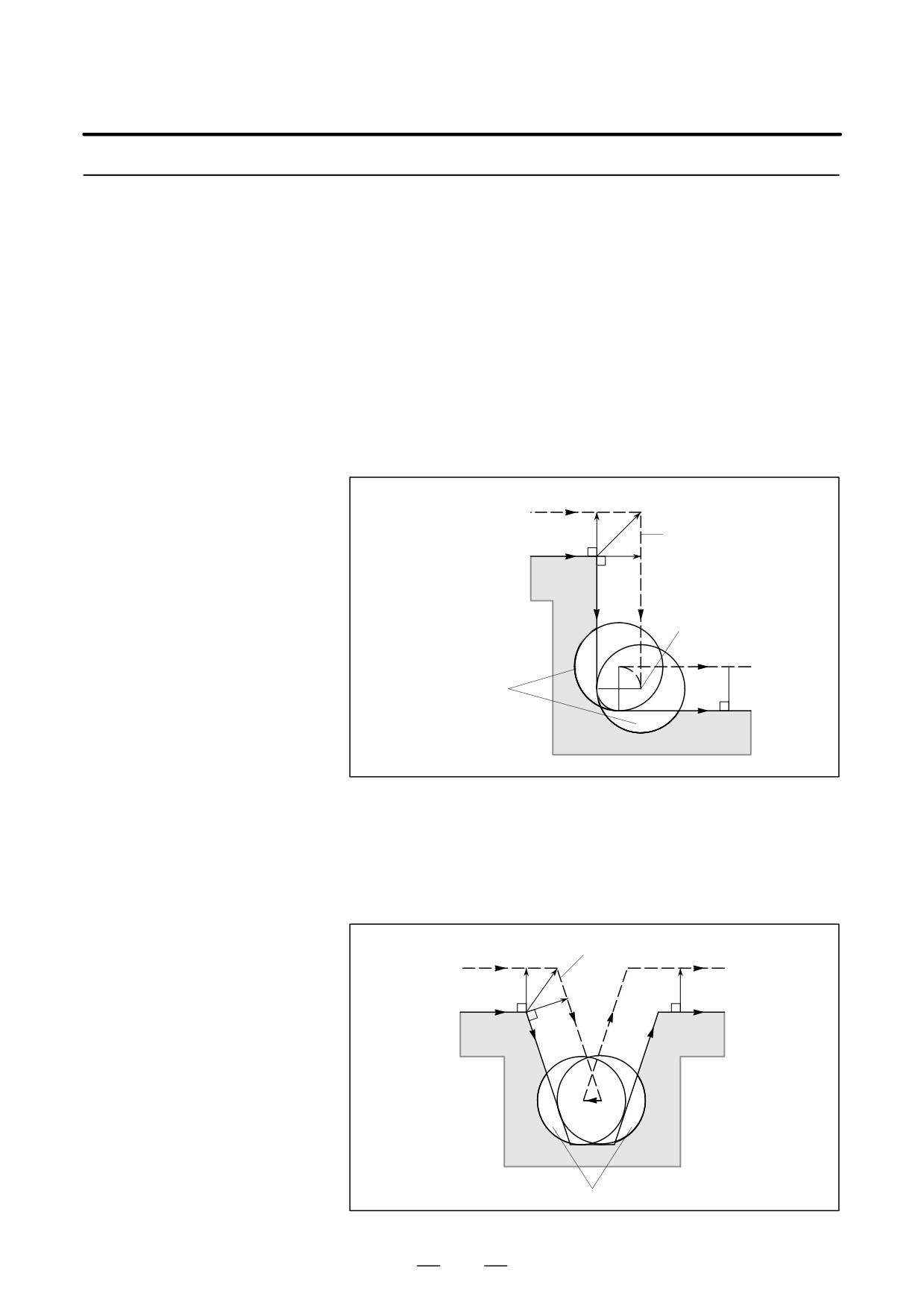
D When interference is
assumed although actual
(1) Depression which is smaller than the cutter compensation value
interference does not
occur
Programmed path Tool center path
Stopped
A
C
B
There is no actual interference, but since the direction programmed in
block B is opposite to that of the path after cutter compensation the tool
stops and an alarm is displayed.
(2) Groove which is smaller than the cutter compensation value
Programmed path Tool center path
Stopped
A
B
C
Like (1), P/S alarm is displayed because of the interference as the
direction is reverse in block B.
258
B-64124EN/01
PROGRAMMING
14. COMPENSATION FUNCTION
14.5.6
Overcutting by Cutter
Compensation
Explanations
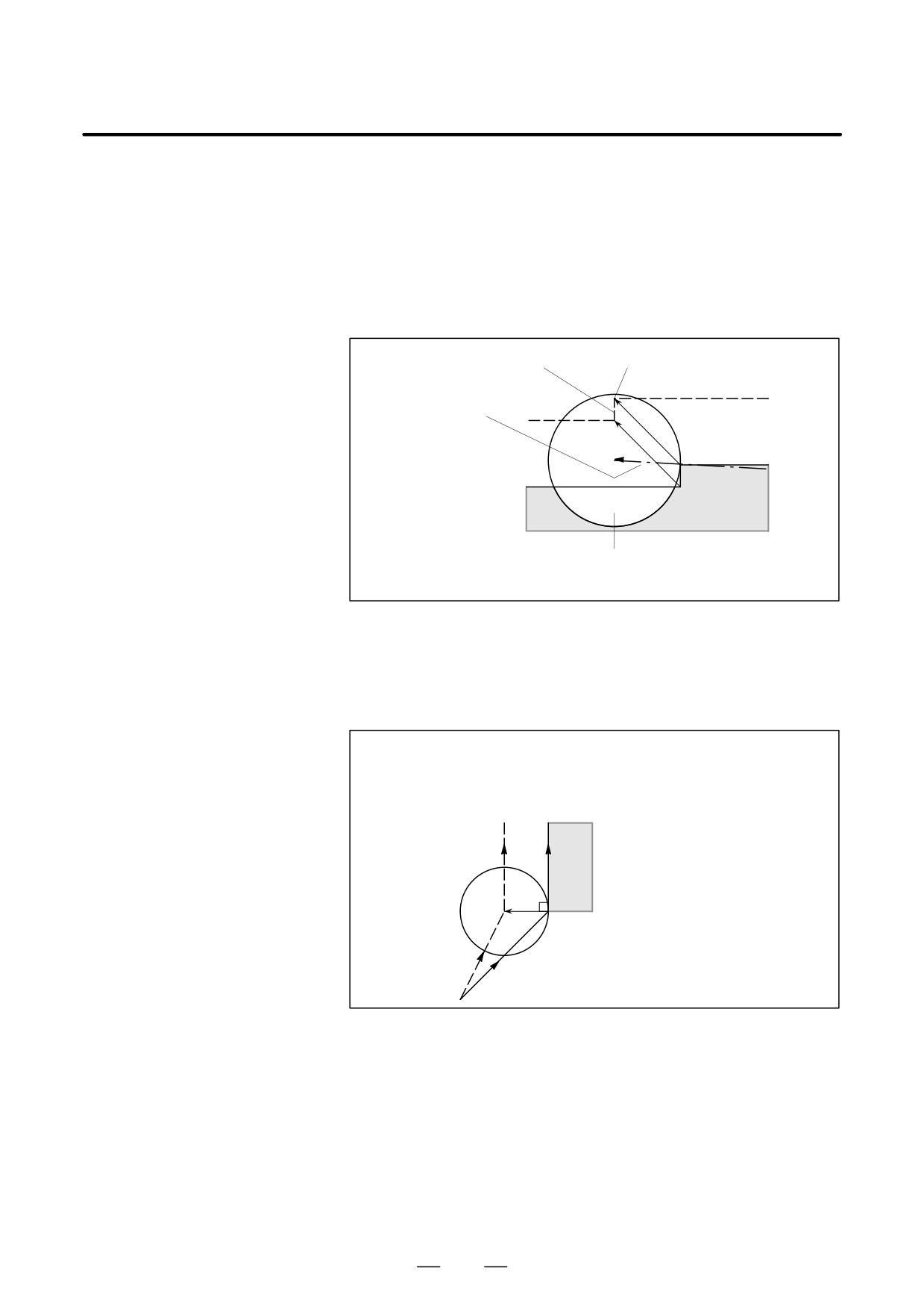
D Machining an inside
When the radius of a corner is smaller than the cutter radius, because the
corner at a radius
inner offsetting of the cutter will result in overcuttings, an alarm is
smaller than the cutter
displayed and the CNC stops at the start of the block. In single block
radius
operation, the overcutting is generated because the tool is stopped after
the block execution.
Tool center path
An alarm is generated
and the operation
Programmed path
stops
Workpiece
An alarm is generated and
the operation stops here in
single block operation
ÇÇ
ÇÇ
If the CNC does not
ÇÇ
stop, overcutting occurs
ÇÇ
ÇÇÇÇ
D Machining a groove
Since the cutter compensation forces the path of the center of the tool to
smaller than the tool
move in the reverse of the programmed direction, overcutting will result.
radius
In this case an alarm is displayed and the CNC stops at the start of the
block.
An alarm is displayed and the operation
Tool center path
stops
Programmed path
Workpiece
ÇÇÇÇÇ
ÇÇÇÇÇÇ
ÇÇÇÇÇÇ
ÇÇÇÇÇ
Overcutting if the operation would not stop
259
14. COMPENSATION FUNCTION
PROGRAMMING
B-64124EN/01
D Machining a step smaller
When machining of the step is commanded by circular machining in the
than the tool radius
case of a program containing a step smaller than the tool radius, the path
of the center of tool with the ordinary offset becomes reverse to the
programmed direction. In this case, the first vector is ignored, and the tool
moves linearly to the second vector position. The single block operation
is stopped at this point. If the machining is not in the single block mode,
the cycle operation is continued. If the step is of linear, no alarm will be
generated and cut correctly. However uncut part will remain.
Linear movement Stop position after execution of a single
block
S
Tool center path
The first vector is ignored
Ç
Ç
Ç
Programmed path
Ç
Ç
Center of the circu-
ÇÇÇÇÇÇ
lar machining
ÇÇÇÇÇ
Workpiece
ÇÇ
An overcutting will result if the first vector is not ignored.
However, tool moves linearly.
D Starting compensation
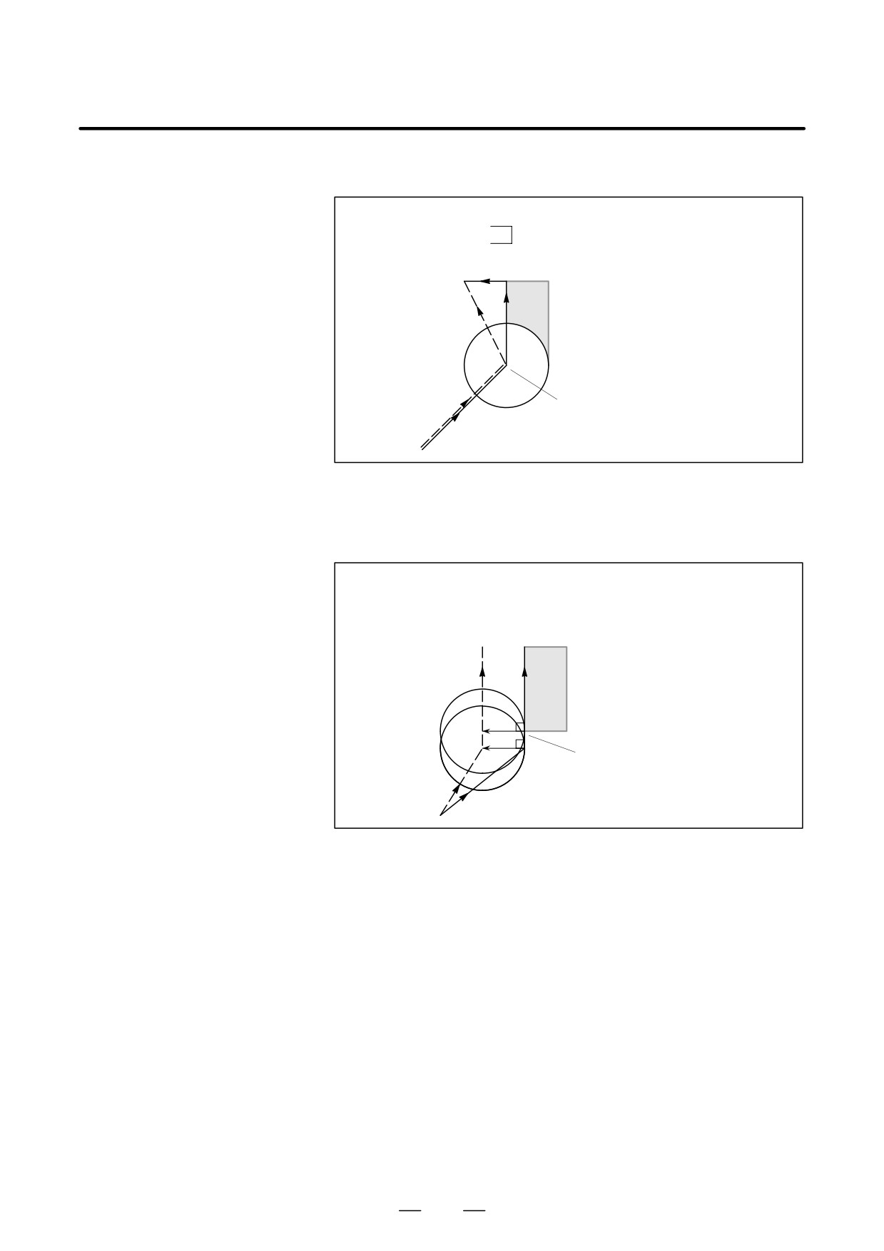
It is usually used such a method that the tool is moved along the Z axis
and cutting along the
after the cutter compensation is effected at some distance from the
Z-axis
workpiece at the start of the machining.
In the case above, if it is desired to divide the motion along the Z axis into
rapid traverse and cutting feed, follow the procedure below.
N1 G91 G00 G41 X500.0 Y500.0 D1 ;
N3 G01 Z-300.0 F100 ;
N6 Y1000.0 F200 ;
After compensation
Work-
piece
N6
ÊÊÊÊ
ÊÊÊÊ
N3:Move command in Z axis
ÊÊÊÊ
(500, 500)
ÊÊÊÊ
N1
In the program example above, when executing block N1, blocks N3 and
N6 are also entered into the buffer storage, and by the relationship among
them the correct compensation is performed as in the figure above.
Then, if the block N3 (move command in Z axis) is divided as follows:
As there are two move command blocks not included in the selected plane
and the block N6 cannot be entered into the buffer storage, the tool center
path is calculated by the information of N1 in the figure above. That is,
the offset vector is not calculated in start-up and the overcutting may
result.
260
B-64124EN/01
PROGRAMMING
14. COMPENSATION FUNCTION
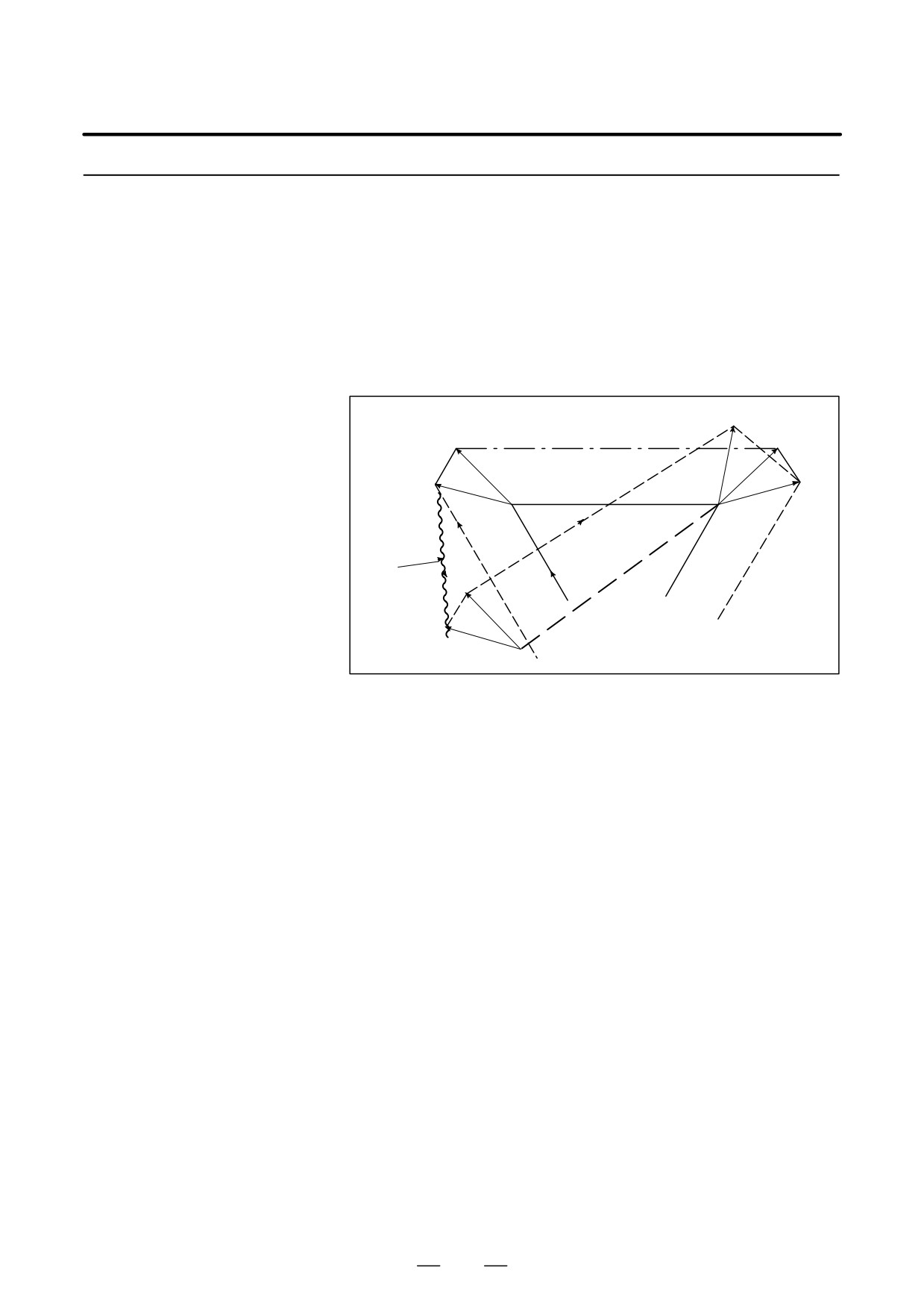
The above example should be modified as follows:
N1 G91 G00 G41 X500.0 Y500.0 D1 ;
N3 G01 Z-250.0 ;
N5 G01 Z-50.0 F100 ;
N6 Y1000.0 F200 ;
Workpiece
After compensation
N6
ÊÊÊÊ
ÊÊÊÊÊ
ÊÊÊÊÊ
N3, N5:Move command for the Z axis
ÊÊÊÊ
(500, 500)
N1
The move command in the same direction as that of the move command
after the motion in Z axis should be programmed.
N1 G91 G00 G41 X500.0 Y400.0 D1 ;
N2 Y100.0 ;
N3 Z-250.0 ;
N5 G01 Z-50.0 F100 ;
N6 Y1000.0 F200 ;
Workpiece
After compensation
N6
ÊÊÊÊ
ÊÊÊÊ
ÊÊÊÊ
N2
N3, N5 : Move command for the Z
ÊÊÊÊ
axis (2blocks)
ÊÊÊÊ
(500, 500)
N1
As the block with sequence No. N2 has the move command in the same
direction as that of the block with sequence No. N6, the correct
compensation is performed.
261
14. COMPENSATION FUNCTION
PROGRAMMING
B-64124EN/01
14.5.7
Cutter compensation C is not performed for commands input from the
MDI.
Input Command from
However, when automatic operation using the absolute commands is
MDI
temporarily stopped by the single block function, MDI operation is
performed, then automatic operation starts again, the tool path is as
follows :
In this case, the vectors at the start position of the next block are translated
and the other vectors are produced by the next two blocks. Therefore,
from next block but one, cutter compensation C is accurately performed.
VC1’
VB2
VC1
VC2
VB1
PC
PB
Command
VB2’
for MDI
PA
PD
VB1’
PB’
When position PA, PB, and PC are programmed in an absolute command,
tool is stopped by the single block function after executing the block from
PA to PB and the tool is moved by MDI operation. Vectors VB1 and VB2
are translated to VB1’ and VB2’ and offset vectors are recalculated for the
vectors VC1 and VC2 between block PB-PC and PC-PD.
However, since vector VB2 is not calculated again, compensation is
accurately performed from position PC.
262
B-64124EN/01
PROGRAMMING
14. COMPENSATION FUNCTION
14.5.8
A function has been added which performs positioning by automatically
canceling a cutter compensation vector when G53 is specified in cutter
G53,G28,G30 and G29
compensation C mode, then automatically restoring that cutter
Commands in Cutter
compensation vector with the execution of the next move command.
Compensation C Mode
The cutter compensation vector restoration mode is of FS16/21/0i type
when CCN (bit 2 of parameter No. 5003) is set to 0; it is of FS15 type when
CCN is set to 1.
When G28 or G30 is specified in cutter compensation C mode, automatic
reference position return is performed by automatically canceling a cutter
compensation vector, that cutter compensation vector automatically
being restored with the execution of the next move command. In this case,
the timing and format of cutter compensation vector
cancellation/restoration, performed when CCN (bit 2 of parameter No.
5003) is set to 1, are changed to FS15 type.
When CCN (bit 2 of parameter No. 5003) is set to 0, the conventional
specification remains applicable.
When G29 is specified in cutter compensation C mode, the cutter
compensation vector is automatically canceled/restored. In this case, the
timing and format of cutter compensation vector cancellation/restoration,
performed when CCN (bit 2 of parameter No. 5003) is set to 1, are
changed to FS15 type.
When CCN (bit 2 of parameter No. 5003) is set to 0, the conventional
specification remains applicable.
Explanations
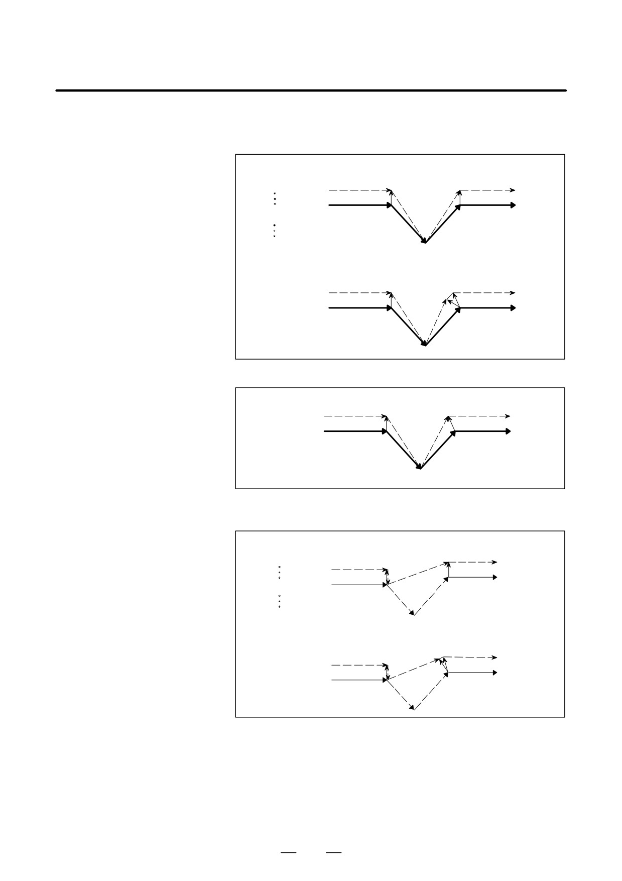
D G53 command in cutter
When G53 is specified in cutter compensation C mode, the previous block
compensation C mode
generates a vector that is perpendicular to the move direction and which
has the same magnitude as the offset value. Then, the offset vector is
canceled when movement to a specified position is performed in the
machine coordinate system. In the next block, offset mode is
automatically resumed.
Note that cutter compensation vector restoration is started when CCN (bit
2 of parameter No. 5003) is set to 0; when CCN is set to 1, an intersection
vector is generated (FS15 type).
263
14. COMPENSATION FUNCTION
PROGRAMMING
B-64124EN/01
(1) G53 specified in offset mode
When CCN (bit 2 of parameter No.5003)=0
Oxxxx;
[Type A]
Start-up
G90G41_ _;
r
r
s
G00
G53X_Y_;
(G41G00)
s
G53
G00
s
[Type B]
Start-up
r
r
s
s
G00
G53
G00
s
When CCN (bit 2 of parameter No.5003)=1
[FS15 Type]
r
(G41G00) s
s
G00
G53
G00
s
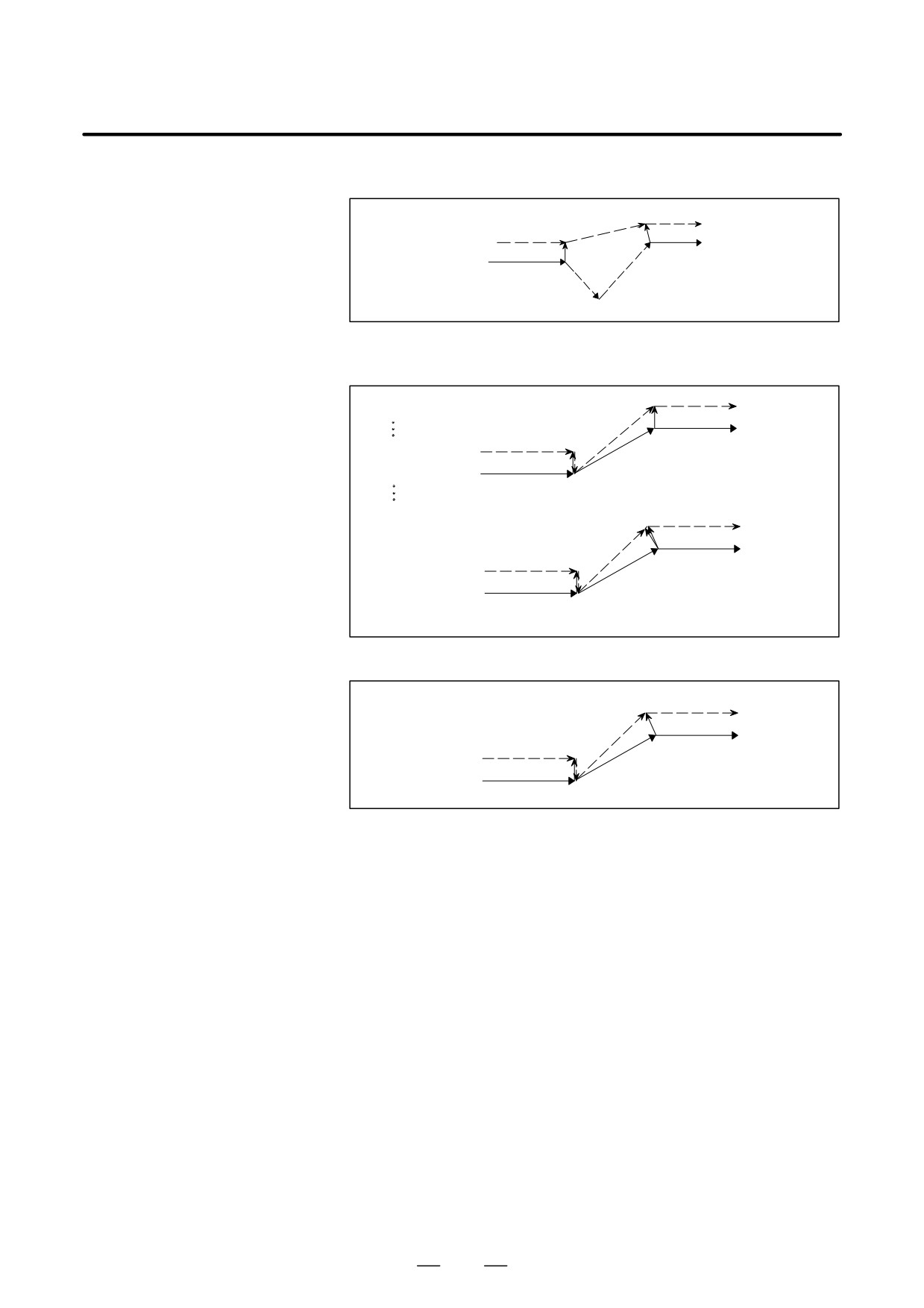
(2) Incremental G53 specified in offset mode
When CCN (bit 2 of parameter No.5003)=0
O××××;
[Type A]
Start-up
G91G41_ _;
r
r
G53X_Y_;
s
G00
s
(G91G41G00)
G53
G90G00
[Type B]
Start-up
r
r
r
s
G00
(G91G41G00)
s
G53
G90G00
264
B-64124EN/01
PROGRAMMING
14. COMPENSATION FUNCTION
When CCN (bit2 of parameter No.5003)=1
[FS15 Type]
r
s
G00
(G91G41G00) s
G53
G90G00
(3) G53 specified in offset mode with no movement specified
When CCN (bit2 of parameter No.5003)=0
[Type A]
Oxxxx;
G90G41_ _;
r
Start-up
s
G00
G00X20.Y20. ;
G00
r
G53X20.Y20. ;
s
(G41G00)
G53
[Type B]
r
Start-up
s
G00
G00
r
s
(G41G00)
G53
When CCN (bit2 of parameter No.5003)=1
[FS15 Type]
s
G00
G00
r
s
(G41G00)
G53
265
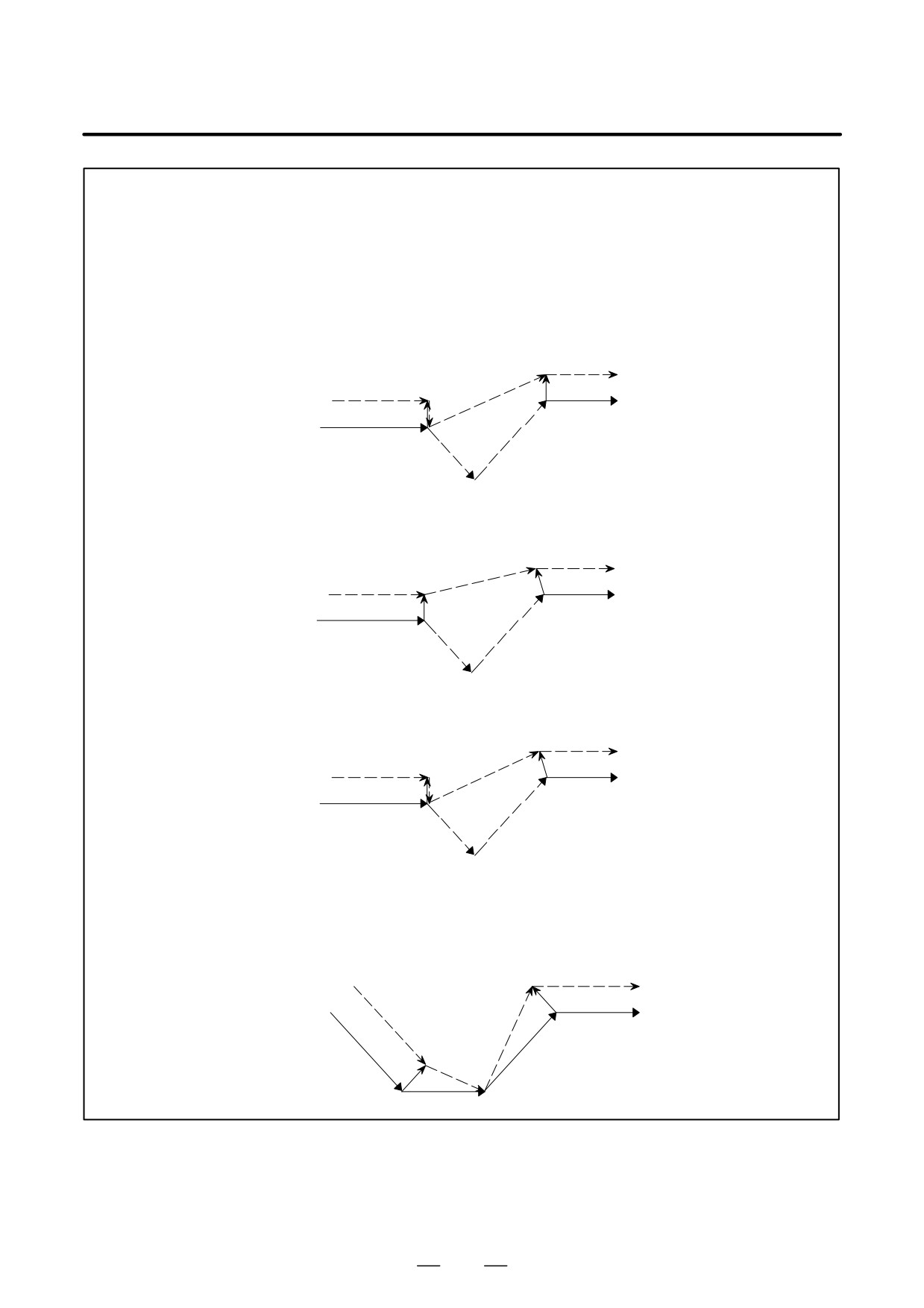
14. COMPENSATION FUNCTION
PROGRAMMING
B-64124EN/01
WARNING
1
When cutter compensation C mode is set and all-axis machine lock is applied, the G53
command does not perform positioning along the axes to which machine lock is applied. The
vector, however, is preserved. When CCN (bit 2 of parameter No. 5003) is set to 0, the vector
is canceled.
(Note that even if the FS15 type is used, the vector is canceled when each-axis
machine lock is applied.)
Example 1:
When CCN (bit 2 of parameter No. 5003) = 0,
type A is used, and all-axis machine lock is applied
r
r
s
G00
(G41G00)
s
G00
G53
Example 2:
When CCN (bit 2 of parameter No. 5003) = 1
and all-axis machine lock is applied [FS15 type]
r
r
s
G00
(G41G00)
s
G00
G53
Example 3:
When CCN (bit 2 of parameter No. 5003) = 1
and specified-axis machine lock is applied [FS15 type]
r
r
s
G00
(G41G00)
s
G00
G53
2
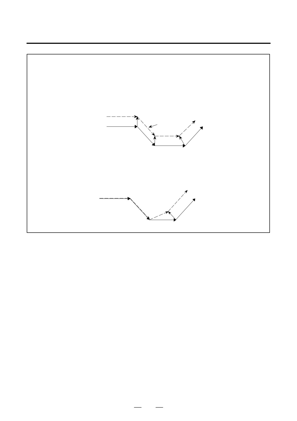
When G53 is specified for a compensation axis in cutter compensation mode, the vectors along
the other axes are also canceled. (This also applies when CCN (bit 2 of parameter No.5003)
is set to 1. When the FS15 type is used, only the vector along a specified axis is canceled.
Note that the FS15 type cancellation differs from the actual FS15 specification in this point.)
Example: When CCN (bit 2 of parameter No.5003)=1[FS 15 type]
G00
s
(G41X_Z_)
G00
r
s
G53Z_
s
266
B-64124EN/01
PROGRAMMING
14. COMPENSATION FUNCTION
NOTE
1
When a G53 command specifies an axis that is not in the cutter compensation C plane, a
perpendicular vector is generated at the end point of the previous block, and the tool does not
move. In the next block, offset mode is automatically resumed (in the same way as when two
or more continuous blocks do not specify any move commands).
Example:
When CCN (bit 2 of parameter No. 5003) = 0, and type A is used
G53Z_
r
Start-up
(G41G00X_Y_)
s
r
G00
G00
s
G00
s
2
When a G53 block is specified to become a start-up block, the next block actually becomes
the start-up block. When CCN (bit 2 of parameter No. 5003) is set to 1, an intersection vector
is generated.
Example:
When CCN (bit 2 of parameter No. 5003) = 0 and type A is used
s
G00
Start-up
G41G53
G00
r
s
s
G00
267
14. COMPENSATION FUNCTION
PROGRAMMING
B-64124EN/01
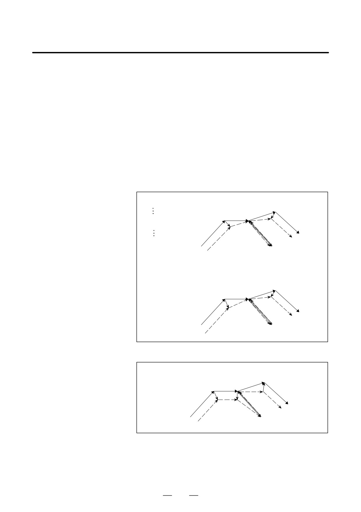
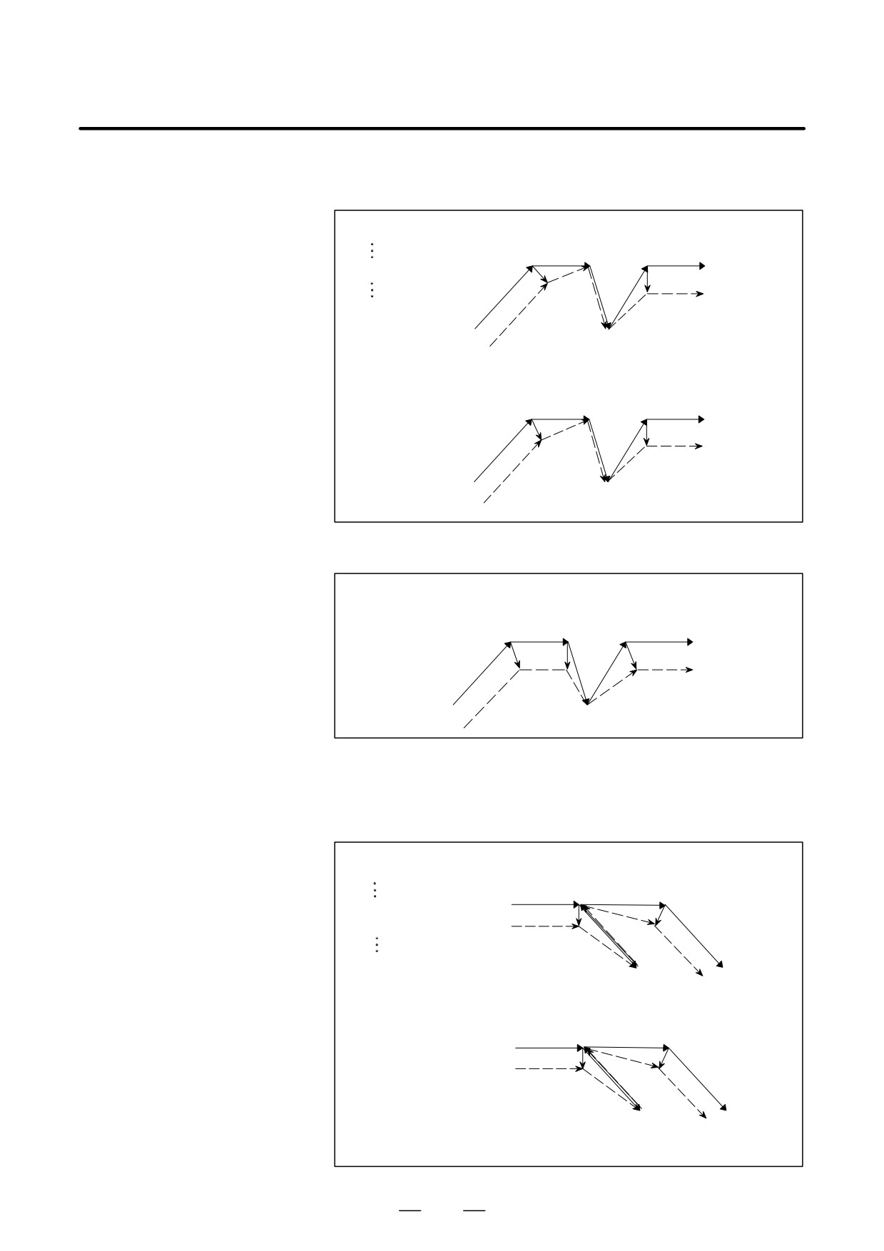
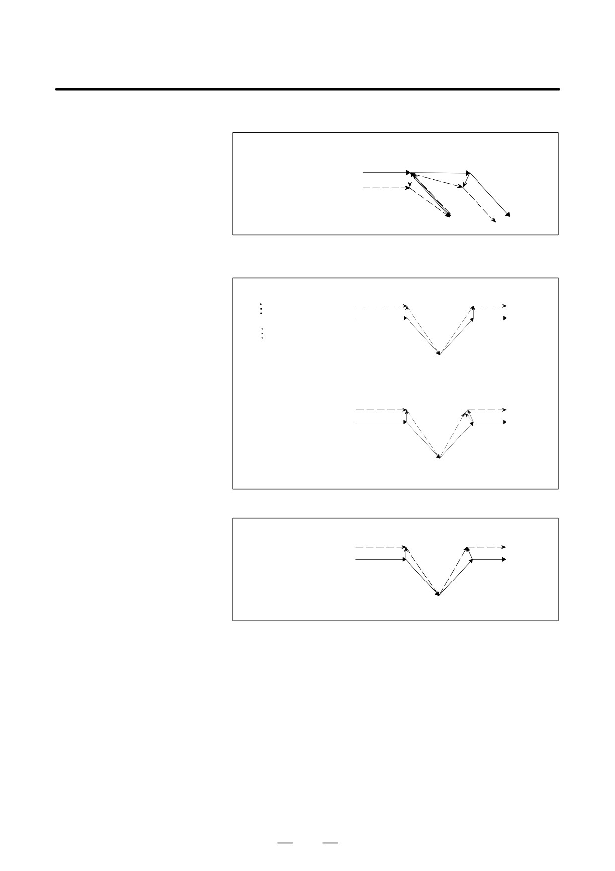
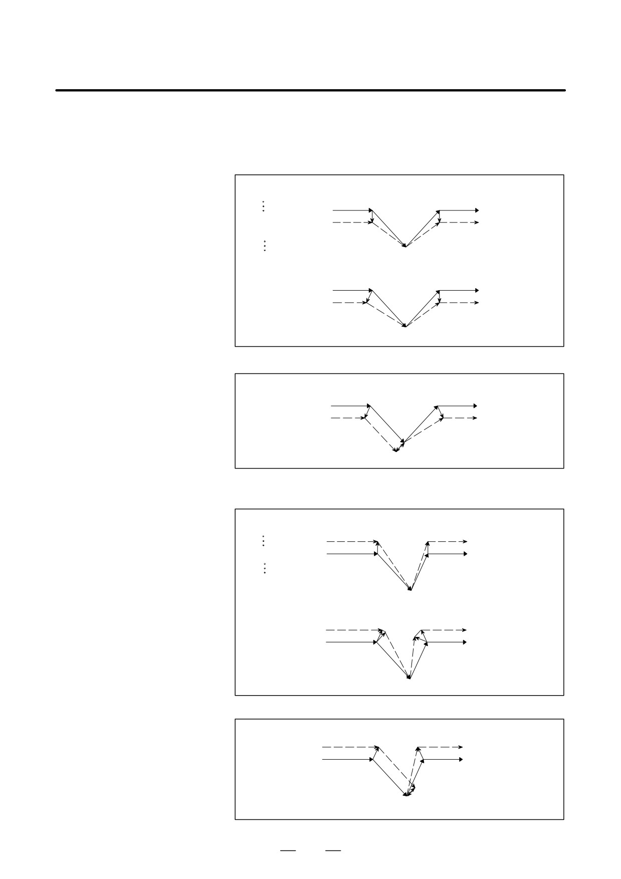
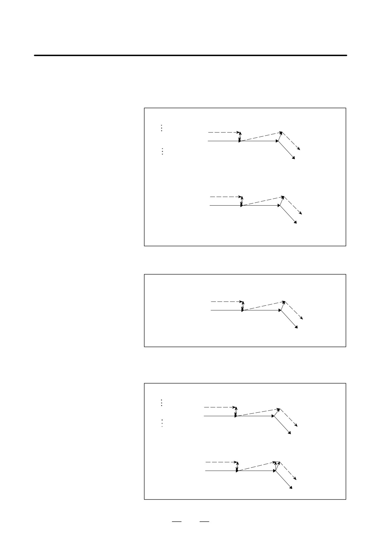
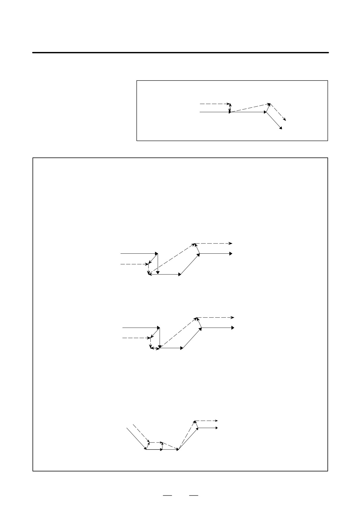
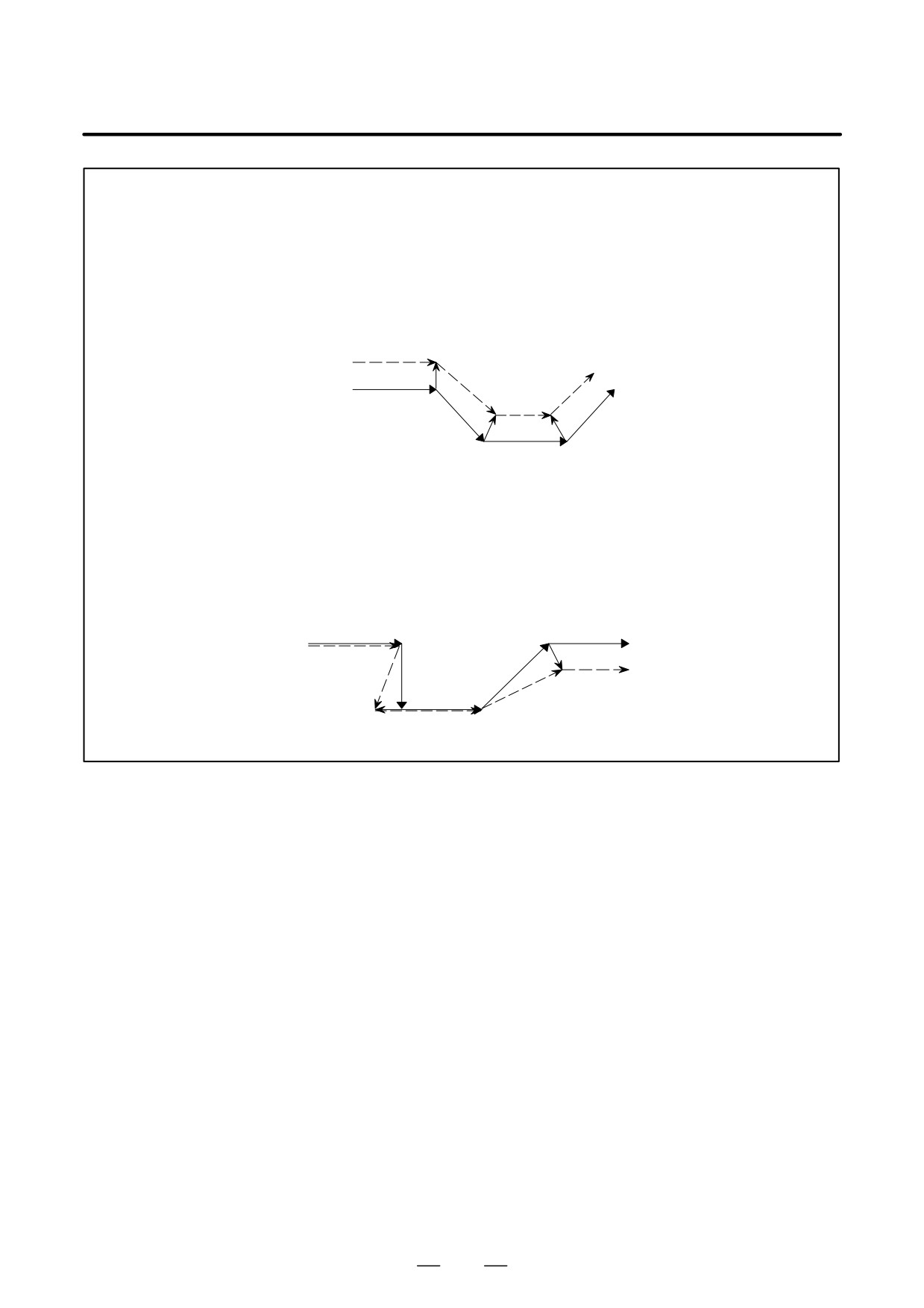
D G28 or G30 command in
When G28 or G30 is specified in cutter compensation C mode, an
cutter compensation C
operation of FS15 type is performed if CCN (bit 2 of parameter No. 5003)
mode
is set to 1.
This means that an intersection vector is generated in the previous block,
and a perpendicular vector is generated at an intermediate position. Offset
vector cancellation is performed when movement is made from the
intermediate position to the reference position. As part of restoration, an
intersection vector is generated between a block and the next block.
(1) G28 or G30, specified in offset mode (with movement to both an
intermediate position and reference position performed)
(a) For return by G29
When CCN (bit 2 of parameter No. 5003) = 0
Oxxxx;
Intermediate
[Type A]
G91G41_ _ _;
position
G28/30
s Return posiiton
s
r
G01
G28X40.Y0 ;
s
G29X45.Y15. ;
(G42G01)
r
G29
s
Reference position
[Type B]
Intermediate
position
Return posiiton
G28/30
s
(G42G01)
s
s
r
G01
G29
s
Reference position
When CCN (bit 2 of parameter No. 5003) = 1
[FS15 Type]
Intermediate
position
G28/30
s
Return posiiton
s
s
G01
r
(G42G01)
G29
s
Reference position
268
B-64124EN/01
PROGRAMMING
14. COMPENSATION FUNCTION
(b) For return by G00
When CCN (bit 2 of parameter No. 5003) = 0
Oxxxx;
[Type A]
G91G41_ _ _;
Intermediateposition
G28/30
s
s
s G01
G28X40.Y0 ;
r
G00
r
(G42G01)
s
Reference position
[Type B]
Intermediateposition
G28/30
s
s
s G01
r
G00
r
(G42G01)
s
Reference position
When CCN (bit 2 of parameter No. 5003) = 1
[FS15 Type]
Intermediateposition
G28/30
s
s
s G01
r
r
(G42G01)
G00
Reference position
s
(2) G28 or G30, specified in offset mode
(with movement
to
an
intermediate position not performed)
(a) For return by G29
When CCN (bit 2 of parameter No. 5003) = 0
O××××;
[Type A]
G91G41_ _ _;
Intermediate position = return position
(G42G01)
s
G01
s
G28X0Y0 ;
r
G29X0Y0 ;
G01
G28/30
G29
Reference position
s
[Type B]
Intermediate position = return position
(G42G01)
s
G01
s
r
G01
G29
G28/30
Reference position
s
269
14. COMPENSATION FUNCTION
PROGRAMMING
B-64124EN/01
When CCN (bit 2 of parameter No. 5003) = 1
[FS15 Type]
Intermediate position = return position
(G42G01)
s
G01
s
r
G01
G28/30
G29
Reference position
s
(b) For return by G00
When CCN (bit 2 of parameter No.5003)=0
Oxxxx;
[Type A]
G91G41_ _ _;
Start-up
r
r
(G42G01)
G28X0Y0 ;
s
s
G01
Intermediate
position
G00
s
G28/30
Reference position
[Type B]
Start-up
r
r
(G42G01)
s
s G01
Intermediate
s
G00
position
G28/30
Reference position
When CCN (bit 2 of parameter No.5003)=1
[FS15 Type]
s
r
(G41G01)
Intermediate
s
G01
position
s
G00
G28/30
Reference position
270
B-64124EN/01
PROGRAMMING
14. COMPENSATION FUNCTION
(3) G28 or G30, specified in offset mode
(with movement to a reference position not performed)
(a) For return by G29
When CCN (bit 2 of parameter No.5003)=0
Oxxxx;
[Type A]
G91G41_ _ _;
Return position
(G42G01) s
s
G01
r
G28/30
r
G28X40.Y-40.;
G29
G29X40.Y40.;
s
Reference position
=Intermediateposition
[Type B]
Return position
(G42G01)
s
s
G01
G28/30
r
r
G29
Reference position
s
=Intermediateposition
When CCN (bit 2 of parameter No.5003)=1
[FS15 Type]
Return position
(G42G01)
s
s
G01
G28/30
G29
s
Reference position
r
=Intermediateposition
(b) For return by G00
When CCN (bit 2 of parameter No.5003)=0
Oxxxx;
[Type A]
G91G41_ _ _;
Start-up
r
r
G28X40.Y-40.;
(G41G01)
s
s G01
G00
s
G28/30
Reference position
=Intermediateposition
[Type B]
Start-up
r
r
(G41G01)
s
s
G01
G28/30
s G00
Reference position
=Intermediateposition
When CCN (bit 2 of parameter No.5003)=1
[FS15 Type]
(G41G01)
s
s
G01
G28/30
G00
s
Reference position
r
=Intermediateposition
271
14. COMPENSATION FUNCTION
PROGRAMMING
B-64124EN/01
(4) G28 or G30 specified in offset mode (with no movement performed)
(a) For return by G29
When CCN (bit 2 of parameter No.5003)=0
O××××;
[Type A]
G91G41_ _ _;
Intersection vector
G28/30/G29
G28X0Y0;
r
(G41G01)
G29X0Y0;
s
G01
G01
Reference position
=Intermediateposition
=return position
[Type B]
Intersection vector
G28/30/G29
r
(G41G01)
s
G01
G01
Reference position
=Intermediateposition
=return position
When CCN (bit 2 of parameter No.5003)=1
[FS15 Type]
G28/30/G29
Intersection vector
(G42G01) r
s
G01
Reference position
G01
=Intermediateposition
=return position
(b) For return by G00
When CCN (bit 2 of parameter No.5003)=0
O××××;
[Type A]
G91G41_ _ _;
G28/30
Start-up
G28X0Y0;
(G41G01) r
s
G00
s
Reference position
=Intermediateposition
G01
[Type B]
Start-up
G28/30
(G41G01)
r
r
s
G00
s
Reference position
=Intermediateposition
G01
272
B-64124EN/01
PROGRAMMING
14. COMPENSATION FUNCTION
When CCN (bit 2 of parameter No.5003)=1
[FS15 Type]
G28/30
r
(G41G01)
s
G00
Reference position
G01
=Intermediateposition
WARNING
1
When a G28 or G30 command is specified during all-axis machine lock, a perpendicular offset
vector is applied at the intermediate position, and movement to the reference position is not
performed; the vector is preserved. Note, however, that even if the FS15 type is used, the
vector is canceled only when each-axis machine lock is applied.
(The FS15 type preserves the vector even when each-axis machine lock is applied.)
Example1: When CCN (bit 2 of parameter No.5003)=1
and all-axis machine lock is applied
[FS15Type ]
(G42G01)
rs
G28
s
G01
G01
r
Reference position or floating
s
s
Intermediateposition
reference position
Example2: When CCN (bit 2 of parameter No.5003)=1
and each-axis machine lock is applied
[FS15Type]
(G42G01)
s
G28
s
G01
G01
r
Reference position or floating
s
s
Intermediateposition
reference position
2
When G28 or G30 is specified for a compensation axis in cutter compensation mode, the
vectors along the other axes are also canceled.
(This also applies when CCN (bit 2 of
parameter No. 5003) is set to 1. When the FS15 type is used, only the vector along a specified
axis is canceled. Note that the FS15 type cancellation differs from the actual FS15 specification
in this point.)
Example:
When CCN (bit 2 of parameter No.5003)=1
s
G00
(G41G00X_Z_)
s s
G00
r
G28Z_
Reference position or floating
Intermediateposition
reference position
273
14. COMPENSATION FUNCTION
PROGRAMMING
B-64124EN/01
NOTE
1
When a G28 or G30 command specifies an axis that is not in the cutter compensation C plane,
a perpendicular vector is generated at the end point of the previous block, and the tool does
not move. In the next block, offset mode is automatically resumed (in the same way as when
two or more continuous blocks do not specify any move commands).
Example:
When CCN (bit 2 of parameter No. 5003) = 1
[FS15 Type]
G28(G30/30.1)Z__
r
(G41G01X_Y_)
s
G01
G01
s
s
2
When a G28 or G30 block is specified such that the block becomes a start-up block, a vector
perpendicular to the move direction is generated at an intermediate position, then subsequently
canceled at the reference position. In the next block, an intersection vector is generated.
Example:
When CCN (bit 2 of parameter No.5003)=1
[FS15 Type]
G01
G01
s
s
G42G28
G01
r
Reference position or floating
reference position
Intermediateposition
s
s
274
B-64124EN/01
PROGRAMMING
14. COMPENSATION FUNCTION
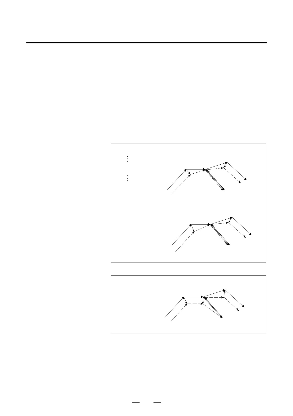
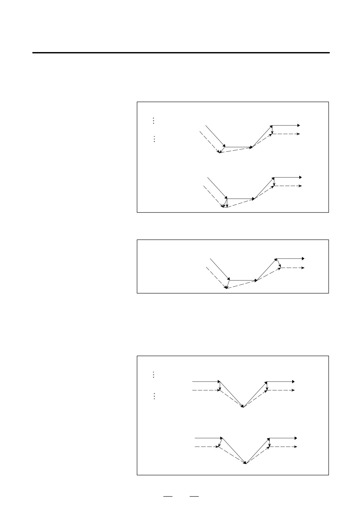
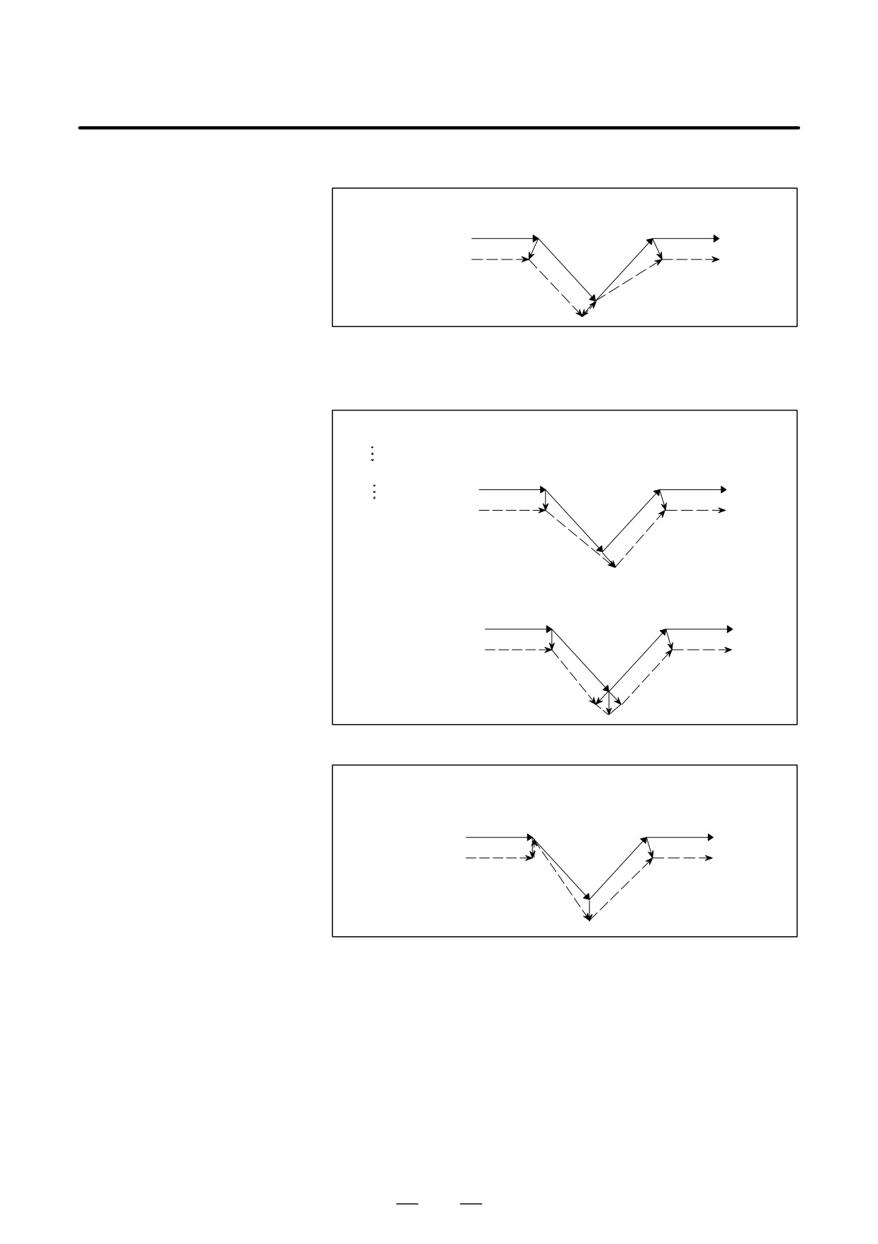
D G29 command in cutter
When G29 is specified in cutter compensation C mode, an operation of
compensation C mode
FS15 type is performed if CCN (bit 2 of parameter No. 5003) is set to 1.
This means that an intersection vector is generated in the previous block,
and vector cancellation is performed when a movement to an intermediate
position is performed. When movement from the intermediate position
to the return position is performed, the vector is restored; an intersection
vector is generated between the block and the next block.
(1) G29 specified in offset mode (with movement to both an intermediate
position and reference position performed)
(a) For specification made immediately after automatic reference
position return
When CCN (bit 2 of parameter No.5003)=0
O××××;
[Tlype A]
G91G41_ _ _;
Intermediate
position
Return position
s
G28/30
G28X40.Y0;
s
s
G01
G29X45.Y15.;
r
(G42G01)
G29
s
Reference position
[Type B]
Intermediateposition
Return position
s
G28/30
G01
s
s
(G42G01)
G29
s
Reference position
When CCN (bit 2 of parameter No.5003)=1
[FS15Type]
Intermediate
Return position
position
s
G28/30
s
s
G01
r
(G42G01)
G29
s
Reference position
275
14. COMPENSATION FUNCTION
PROGRAMMING
B-64124EN/01
(b) For specification made other than immediately after automatic
reference position return
When CCN (bit 2 of parameter No.5003)=0
O××××;
[Type A]
G91G41_ _ _;
Return position
G01
(G42G01)
s
G29X40.Y40.;
Intermediate
r
position
s
G29
s
Start-up
r
[Type B]
Return position
s
G01
(G42G01)
r
Intermediate
position
s
G29
s
r
Start-up
When CCN (bit 2 of parameter No.5003)=1
[FS15 Type]
Return position
s
G01
(G42G01)
Intermediate
position
s
G29
s
(2) G29 specified in offset mode (with movement to an intermediate
position not performed)
(a) For specification made immediately after automatic reference
position return
When CCN (bit 2 of parameter No.5003)=0
O××××;
[Type A]
G91G41_ _ _;
Return position
(G42G01)
s
s
G01
G28X40.Y-40.;
G28/30
r
r
G29X40.Y40.;
G29
s
Reference position
=Intermediateposition
[Type B]
(G42G01)
Return position
s
s G01
G28/30
r
G29
s
Reference position
=Intermediateposition
276
B-64124EN/01
PROGRAMMING
14. COMPENSATION FUNCTION
When CCN (bit 2 of parameter No.5003)=1
[FS15 Type]
Return position
(G42G01)
s
s
G01
G28/30
G29
Reference position
s
=Intermediateposition
r
(b) For specification made other than immediately after automatic
reference position return
When CCN (bit 2 of parameter No.5003)=0
O××××;
[Type A]
G91G41_ _ _;
Intermediateposition
G29X40.Y-40.;
(G42G01)
s
s G01
r
G29
G01
Start-up
s
r
[Type B]
Return position
Intermediateposition
(G42G01) s
s
G01
r
G29
G01
Start-up
s
r
r
Return position
When CCN (bit 2 of parameter No.5003)=1
[FS15 Type]
Intermediateposition
(G42G01)s
s
G01
r
G29
G01
s
Return position
277
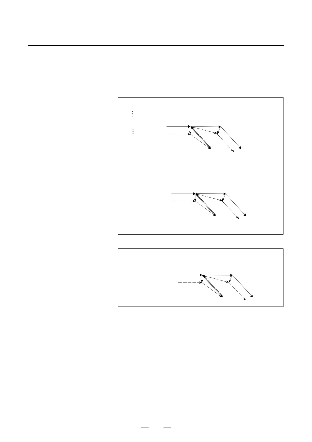
14. COMPENSATION FUNCTION
PROGRAMMING
B-64124EN/01
(3) G29 specified in offset mode (with movement to a reference position
not performed)
(a) For specification made immediately after automatic
reference
position return
When CCN (bit 2 of parameter No.5003)=0
O××××;
[Type A]
G91G41_ _ _;
Intermediateposition
=Return position
G28X0Y0;
(G42G01)
G01
s
s
G29X0Y0;
r
G01
G28/30
G29
s
Reference position
[Type B]
Intermediateposition
=Return position
(G42G01)
s
G01
s
r
G01
G28/30
G29
s
Reference position
When CCN (bit 2 of parameter No.5003)=1
[FS15 Type]
Intermediateposition
=Return position
(G42G01)
s
s
G01
r
G01
G28/30
G29
Reference position
s
278
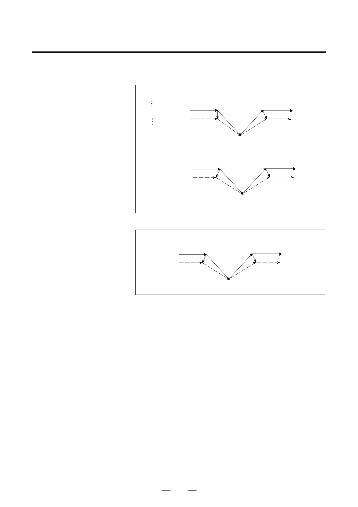
B-64124EN/01
PROGRAMMING
14. COMPENSATION FUNCTION
(b) For specification made other than immediately after automatic
reference position return
O××××;
[Type A]
G91G41_ _ _;
(G42G01)
s
s
G01
G29X0Y0;
r
G29
G01
s
Intermediateposition
=Return position
[Type B]
(G42G01)
s
s
G01
G29
G01
s
Intermediate position
=Return position
When CCN (bit 2 of parameter No.5003)=1
[FS15 Type]
(G42G01)
s
s G01
G29
G01
s
Intermediateposition
=Return position
279
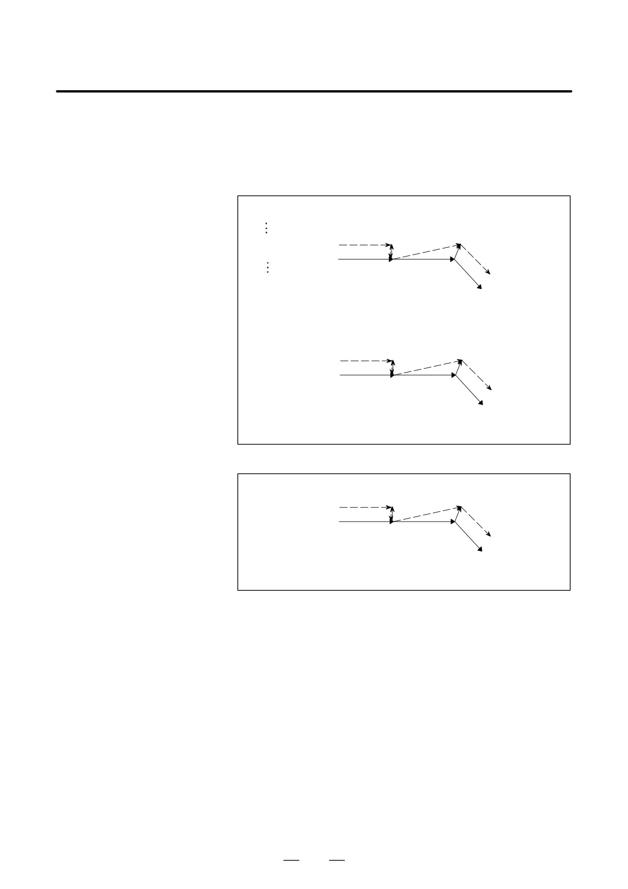
14. COMPENSATION FUNCTION
PROGRAMMING
B-64124EN/01
(4) G29 specified in offset mode (with movement to an intermediate
position and reference position not performed)
(a) For specification made immediately after automatic reference
position return
When CCN (bit 2 of parameter No.5003)=0
O××××;
[Type A]
G91G41_ _ _;
G28/30,G29
Intersection vector
G28X0Y0;
s
G29X0Y0;
(G41G01)
r
G01
s
s
G01
Reference position
=Intermediate position
=return position
[Type B]
G28/30,G29
Intersection vector
(G41G01)r
s
G01
s
G01
Reference position
=Intermediate position
=return position
When CCN (bit 2 of parameter No.5003)=1
[FS15 Type]
G28/30,G29
Intersection vector
(G42G01) r
G01
s
s
G01
Reference position
=Intermediateposition
=return position
280
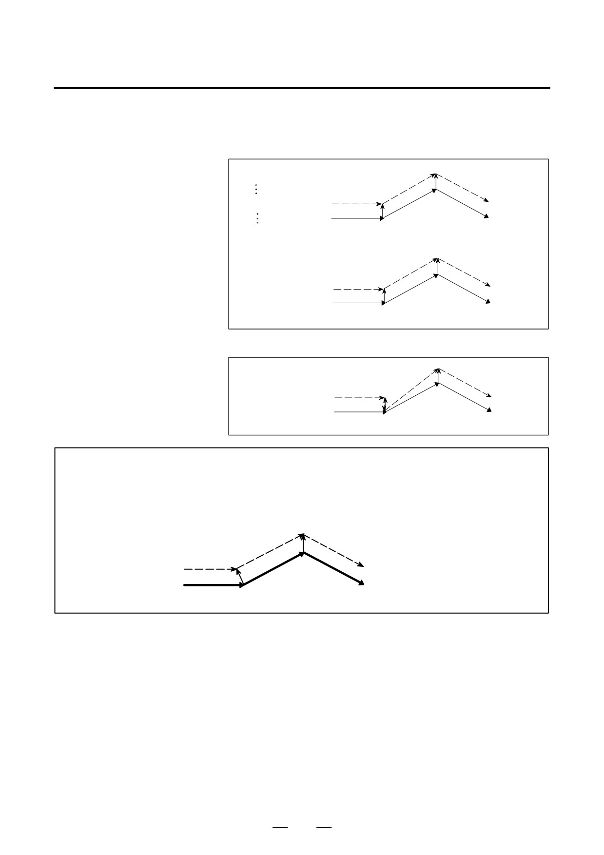
B-64124EN/01
PROGRAMMING
14. COMPENSATION FUNCTION
(b) For specification made other than immediately after automatic
reference position return
When CCN (bit 2 of parameter No.5003)=0
O××××;
[Type A]
G91G41_ _ _;
G29
s
G29X0Y0;
G01
(G41G01) r
G01
s
Intermediate position=return position
[Type B]
G29
s
r
G01
G01
(G41G01)
s
Intermediate position=return position
When CCN (bit 2 of parameter No.5003)=1
[FS15 Type]
s
G29
G01
G01
r
(G41G01)
s
Intermediate position=return position
NOTE
When a G29 command is specified for an axis that is not in the cutter compensation C plane
in cutter compensation C mode, a perpendicular vector is generated at the end point of the
previous block, and the tool does not move. In the next block, an intersection vector is
generated (in the same way as when two or more continuous blocks do not specify any move
commands).
G29Z__
s
r
G01
G01
s
(G41G01X_Y_)
281
14. COMPENSATION FUNCTION
PROGRAMMING
B-64124EN/01
14.5.9
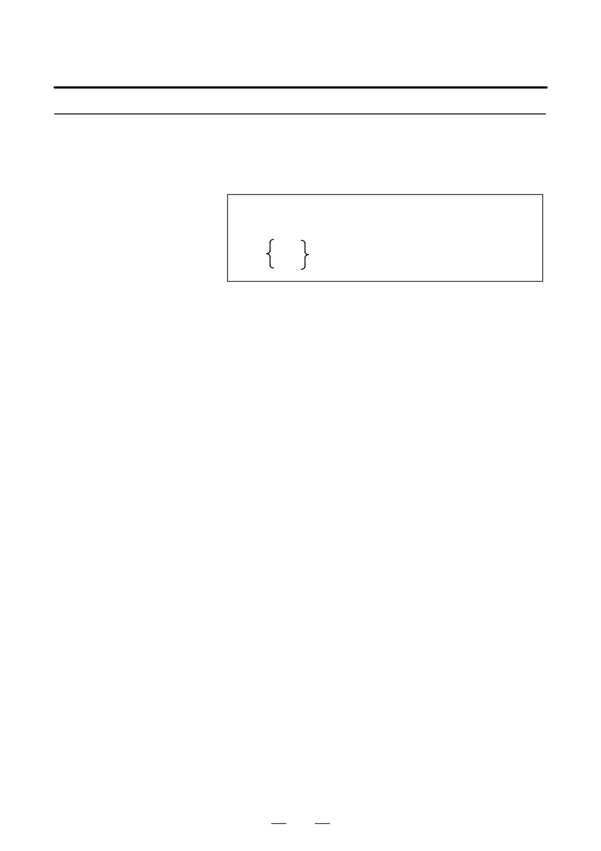
By specifying G39 in offset mode during cutter compensation C, corner
circular interpolation can be performed. The radius of the corner circular
Corner Circular
interpolation equals the compensation value.
Interpolation (G39)
Format
In offset mode
G39 ;
or
I_J_
G39
I_K_
;
J_K_
Explanations
D Corner circular
When the command indicated above is specified, corner circular
interpolation
interpolation in which the radius equals compensation value can be
performed. G41 or G42 preceding the command determines whether the
arc is clockwise or counterclockwise. G39 is a one-shot G code.
D G39 without I, J, or K
When G39; is programmed, the arc at the corner is formed so that the
vector at the end point of the arc is perpendicular to the start point of the
next block.
D G39 with I, J, and K
When G39 is specified with I, J, and K, the arc at the corner is formed so
that the vector at the end point of the arc is perpendicular to the vector
defined by the I, J, and K values.
Limitations
D Move command
In a block containing G39, no move command can be specified.
D Non-move command
Two or more consecutive non-move blocks must not be specified after a
block containing G39 without I, J, or K.
(A single block specifying a
travel distance of zero is assumed to be two or more consecutive
non-move blocks.) If the non-move blocks are specified, the offset
vector is temporarily lost. Then, offset mode is automatically restored.
282