FANUC Series 0i-MC. OPERATOR’S MANUAL - page 5
8. COORDINATE VALUE
B-64124EN/01
PROGRAMMING
AND DIMENSION
Either inch or metric input can be selected by G code.
8.3
INCH/METRIC
CONVERSION
(G20,G21)
Format
G20 ; Inch input
G21 ;mm input
This G code must be specified in an independent block before setting the
coordinate system at the beginning of the program. After the G code for
inch/metric conversion is specified, the unit of input data is switched to
the least inch or metric input increment of increment system IS-B or IS-C
(II-2.3). The unit of data input for degrees remains unchanged.The unit
systems for the following values are changed after inch/metric
conversion:
- Feedrate commanded by F code
- Positional command
- Work zero point offset value
- Tool compensation value
- Unit of scale for manual pulse generator
- Movement distance in incremental feed
- Some parameters
When the power is turned on, the G code is the same as that held before
the power was turned off.
WARNING
1
G20 and G21 must not be switched during a program.
2
When switching inch input (G20) to metric input (G21) and vice versa, the tool compensation
value must be re-set according to the least input increment.
However, when bit 0 (OIM) of parameter 5006 is 1, tool compensation values are automatically
converted and need not be re-set.
CAUTION
For the first G28 command after switching inch input to metric input or vice versa, operation from
the intermediate point is the same as that for manual reference position return. The tool moves
from the intermediate point in the direction for reference position return, specified with bit 5
(ZMI) of parameter No. 1006.
NOTE
1
When the least input increment and the least command increment systems are different, the
maximum error is half of the least command increment. This error is not accumulated.
2
The inch and metric input can also be switched using settings. (See III-11.4.3)
103
8. COORDINATE VALUE
AND DIMENSION
PROGRAMMING
B-64124EN/01
Numerical values can be entered with a decimal point. A decimal point
8.4
can be used when entering a distance, time, or speed. Decimal points can
DECIMAL POINT
be specified with the following addresses:
PROGRAMMING
X, Y, Z, U, V, W, A, B, C, I, J, K, Q, R, and F.
Explanations
There are two types of decimal point notation: calculator-type notation
and standard notation.
When calculator-type decimal notation is used, a value without decimal
point is considered to be specified in millimeters inch,or deg. When
standard decimal notation is used, such a value is considered to be
specified in least input increments.Select either calculator-type or
standard decimal notation by using the DPI bit (bit 0 of parameter
3401).Values can be specified both with and without decimal point in a
single program.
Examples
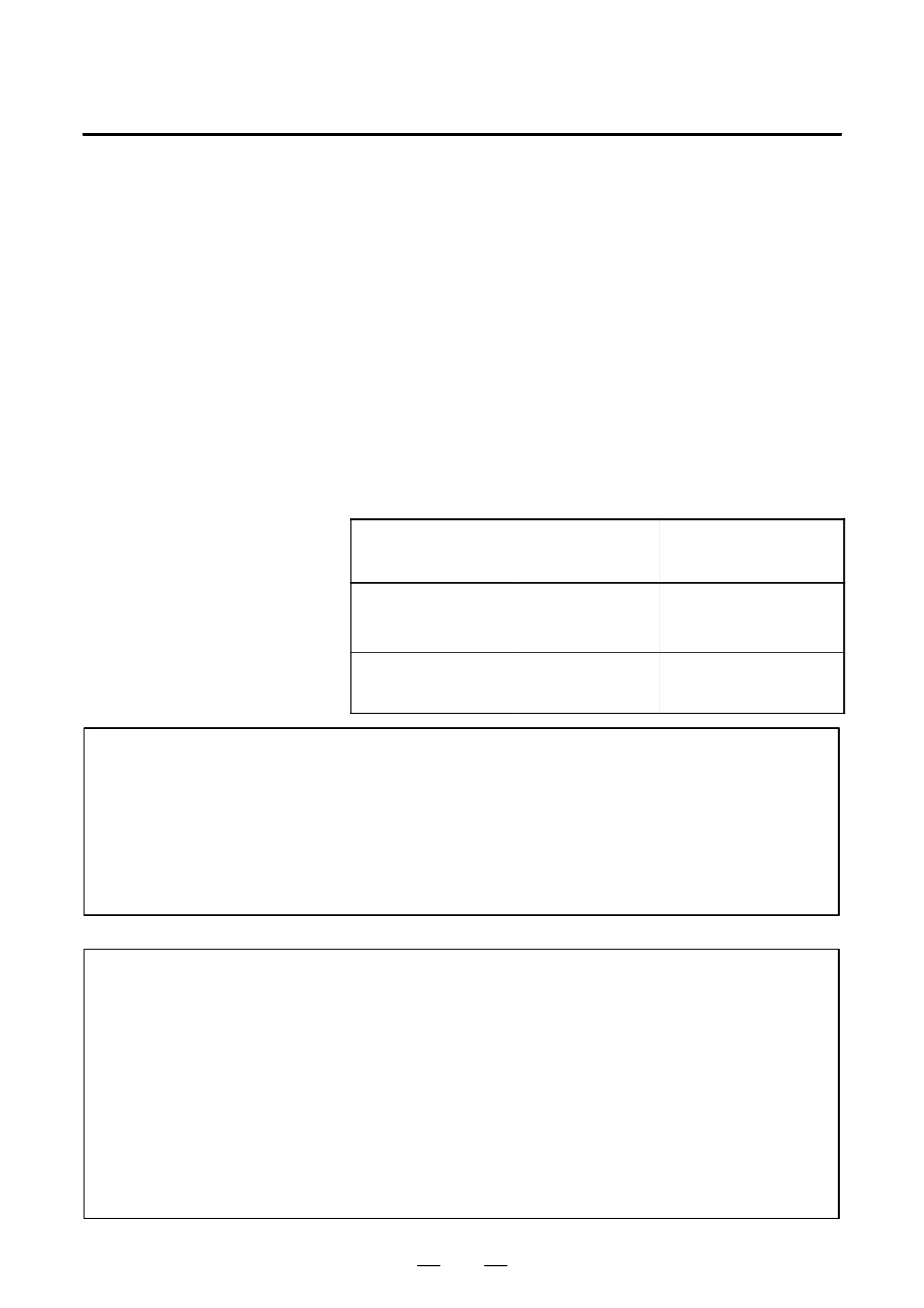
Pocket calculator
Standard type decimal
Program command
type decimal point
point programming
programming
X1000
1000mm
1mm
Command value without
Unit : mm
Unit : Least input increment
decimal point
(0.001 mm)
X1000.0
1000mm
1000mm
Command value with
Unit : mm
Unit : mm
decimal point
WARNING
In a single block, specify a G code before entering a value. The position of decimal point may
depend on the command.
Examples:
G20;
Input in inches
X1.0 G04;
X1.0 is considered to be a distance and processed as X10000. This command
is equivalent to G04 X10000. The tool dwells for 10 seconds.
G04 X1.0;
Equivalent to G04 X1000. The tool dwells for one second.
NOTE
1 Fractions less than the least input increment are truncated.
Examples:
X1.23456;
Truncated to X1.234 when the least input increment is 0.001 mm.
Processed as X1.2345 when the least input increment is 0.0001 inch.
2 When more than eight digits are specified, an alarm occurs. If a value is entered with a decimal
point, the number of digits is also checked after the value is converted to an integer according
to the least input increment.
Examples:
X1.23456789; P/S alarm 0.003 occurs because more than eight digits are specified.
X123456.7; If the least input increment is 0.001 mm, the value is converted to integer
123456700. Because the integer has more than eight digits, an alarm occurs.
104
9. SPINDLE SPEED FUNCTION
B-64124EN/01
PROGRAMMING
(S FUNCTION)
SPINDLE SPEED FUNCTION (S FUNCTION)
9
The spindle speed can be controlled by specifying a value following
address S.
This chapter contains the following topics.
9.1 SPECIFYING THE SPINDLE SPEED WITH A CODE
9.2 SPECIFYING THE SPINDLE SPEED VALUE DIRECTLY
9.2 (S5-DIGIT COMMAND)
9.3 CONSTANT SURFACE SPEED CONTROL (G96, G97)
105
9. SPINDLE SPEED FUNCTION
(S FUNCTION)
PROGRAMMING
B-64124EN/01
When a value is specified after address S, the code signal and strobe signal
9.1
are sent to the machine to control the spindle rotation speed.
SPECIFYING THE
A block can contain only one S code. Refer to the appropriate manual
SPINDLE SPEED
provided by the machine tool builder for details such as the number of
digits in an S code or the execution order when a move command and an
WITH A CODE
S code command are in the same block.
9.2
The spindle speed can be specified directly by address S followed by a
max.five-digit value (min-1). The unit for specifying the spindle speed
SPECIFYING THE
may vary depending on the machine tool builder. Refer to the appropriate
SPINDLE SPEED
manual provided by the machine tool builder for details.
VALUE DIRECTLY
(S5-DIGIT
COMMAND)
106
9. SPINDLE SPEED FUNCTION
B-64124EN/01
PROGRAMMING
(S FUNCTION)
Specify the surface speed (relative speed between the tool and workpiece)
9.3
following S. The spindle is rotated so that the surface speed is constant
CONSTANT
regardless of the position of the tool.
SURFACE SPEED
CONTROL (G96, G97)
Format
D Constant surface speed
control command
G96 Sfffff ;
↑ Surface speed (m/min or feet/min)
Note : This surface speed unit may change according to machine tool
builder’s specification.
D Constant surface speed
control cancel command
G97 Sfffff ;
↑ Spindle speed (min-1)
Note : This surface speed unit may change according to machine tool
builder’s specification.
D Constant surface speed
controlled axis
G96 Pα ;P0 : Axis set in the parameter (No. 3770)
command
P1 : X axis, P2 : Y axis, P3 : Z axis, P4 : 4th axis
D Clamp of maximum
spindle speed
G92 S_ ;
The maximum spindle speed (min-1) follows S.
107
9. SPINDLE SPEED FUNCTION
(S FUNCTION)
PROGRAMMING
B-64124EN/01
Explanations
D Constant surface speed
G96 (constant surface speed control command) is a modal G code. After
control command (G96)
a G96 command is specified, the program enters the constant surface
speed control mode (G96 mode) and specified S values are assumed as a
surface speed. A G96 command must specify the axis along which
constant surface speed control is applied. A G97 command cancels the
G96 mode.When constant surface speed control is applied, a spindle
speed higher than the value specified in G92S_; (maximum spindle
speed) is clamped at the maximum spindle speed. When the power is
turned on, the maximum spindle speed is not yet set and the speed is not
clamped.S (surface speed) commands in the G96 mode are assumed as S
= 0 (the surface speed is 0) until M03 (rotating the spindle in the positive
direction) or M04 (rotating the spindle in the negative direction) appears
in the program.
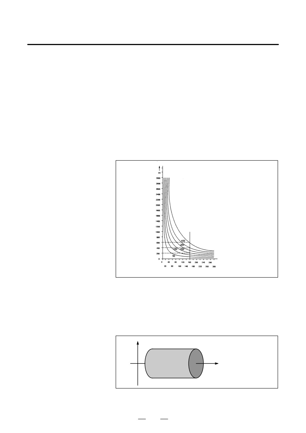
Spindle speed (min-1)
The spindle speed (min-1) almost
coincides with the surface speed
(m/min) at approx. 160 mm (radius).
Surface speed
S is 600 m/min.
radius (mm)
Fig. 9.3 (a) Relation between workpiece radius, spindle speed
and surface speed
D Setting the workpiece
To execute the constant surface speed control, it is necessary to set the
coordinate system for
work coordinate system , and so the coordinate value at the center of the
constant surface speed
rotary axis, for example, Z axis, (axis to which the constant surface speed
control
control applies) becomes zero.
X
Z
0
Fig. 9.3 (b) Example of the workpiece coordinate system for
constant surface speed control
108
9. SPINDLE SPEED FUNCTION
B-64124EN/01
PROGRAMMING
(S FUNCTION)
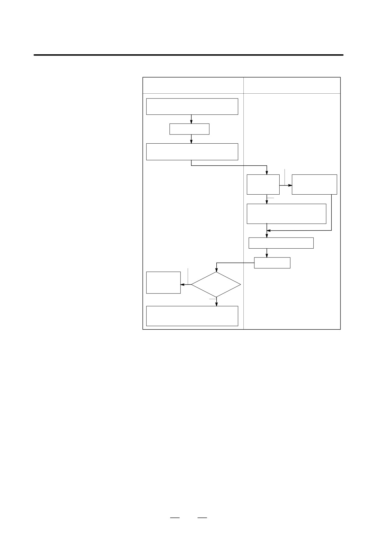
D Surface speed specified
in the G96 mode
G96 mode
G97 mode
Specify the surface speed in m/min
(or feet/min)
G97 command
Store the surface speed in m/min
(or feet/min)
Specified
Command for
The specified
the spindle
spindle speed
speed
(min-1) is used
Not specified
The surface speed (m/min or
feet/min) is converted to the
spindle speed (min-1)
Commands other than G96
G96 command
Specified
The specified
surface
Command
speed is used
for the surface
speed
Not specified
The stored surface speed (m/min or
feet/min) is used. If no surface speed
is stored, 0 is assumed.
Restrictions
D Constant surface speed
The constant surface speed control is also effective during threading.
control for threading
Accordingly, it is recommended that the constant surface speed control
be invalidated with G97 command before starting the scroll threading and
taper threading, because the response problem in the servo system may
not be considered when the spindle speed changes.
D Constant surface speed
In a rapid traverse block specified by G00, the constant surface speed
control for rapid traverse
control is not made by calculating the surface speed to a transient change
(G00)
of the tool position, but is made by calculating the surface speed based on
the position at the end point of the rapid traverse block, on the condition
that cutting is not executed at rapid traverse.
109
10. TOOL FUNCTION
(T FUNCTION)
PROGRAMMING
B-64124EN/01
TOOL FUNCTION (T FUNCTION)
10
General
Two tool functions are available. One is the tool selection function, and
the other is the tool life management function.
110
10. TOOL FUNCTION
B-64124EN/01
PROGRAMMING
(T FUNCTION)
10.1
By specifying an up to 8-digit numerical value following address T, tools
can be selected on the machine.
TOOL SELECTION
One T code can be commanded in a block. Refer to the machine tool
FUNCTION
builder’s manual for the number of digits commandable with address T
and the correspondence between the T codes and machine operations.
When a move command and a T code are specified in the same block, the
commands are executed in one of the following two ways:
(i) Simultaneous execution of the move command and T function
commands.
(ii)Executing T function commands upon completion of move command
execution.
The selection of either (i) or (ii) depends on the machine tool builder’s
specifications. Refer to the manual issued by the machine tool builder
for details.
111
10. TOOL FUNCTION
(T FUNCTION)
PROGRAMMING
B-64124EN/01
10.2
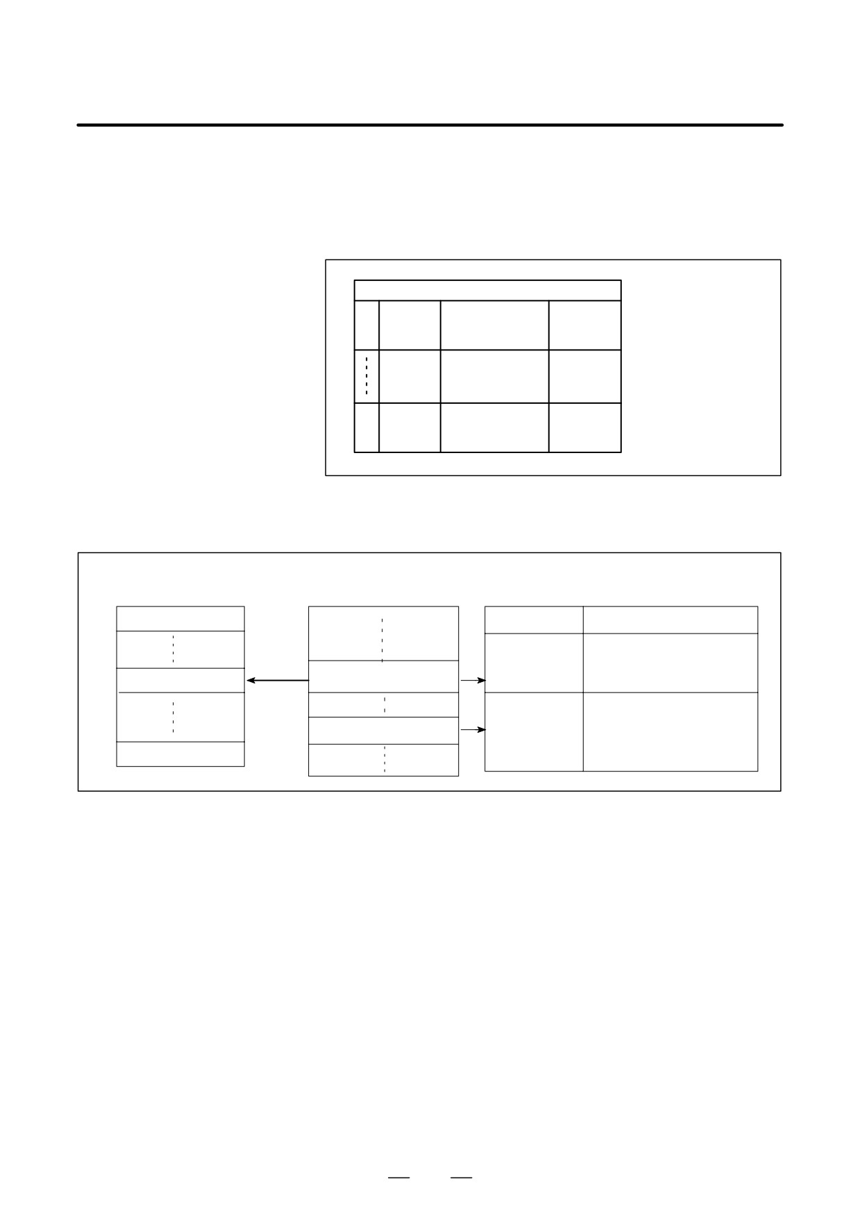
Tools are classified into various groups, with the tool life (time or
frequency of use) for each group being specified. The function of
TOOL LIFE
accumulating the tool life of each group in use and selecting and using
MANAGEMENT
the next tool previously sequenced in the same group, is called the tool
FUNCTION
life management function.
Tool group number m
Code specifying
Tool
1
Tool life
The first tool life
tool compensa-
number
management data
tion value
n
The nth tool life
management data
Fig. 10.2 (a) Tool life management data (number of n tools)
By choosing a tool from a tool group specified by a machining program,
the tool life can be managed.
Tool life management data
Machining program
Machine and CNC operations
Tool group number 1
Machine
CNC
Places a se-
Automatically selects, from
Tool
lected tool in
tool group m, a tool whose
selection
Command for selecting
the wait state
life has not expired.
Tool group number m
tool group m
Attaches the
Starts counting the life of
tool in the wait
Tool change command
the tool attached to the
state to
(M06)
spindle.l
the spindle
Tool group number p
(tool change).
Fig. 10.2 (b) Tool Selection by machining program
112
10. TOOL FUNCTION
B-64124EN/01
PROGRAMMING
(T FUNCTION)
10.2.1
Tool life management data consists of tool group numbers, tool numbers,
codes specifying tool compensation values, and tool life value.
Tool Life Management
Data
Explanations
D Tool group number
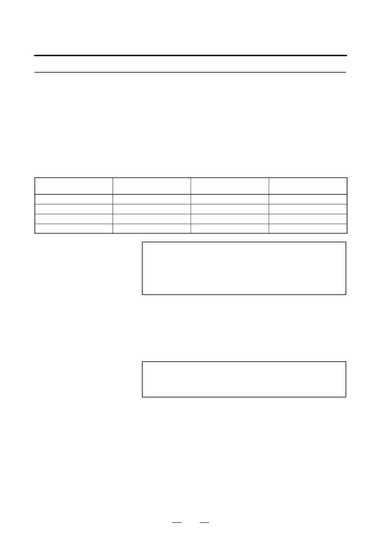
The Max. number of groups and the number of tools per group that can
be registered are set by parameter (GS1,GS2 No. 6800#0, #1) (Table
10.2.1).
Table 10.2.1 The Max. number of groups and tools that can be registered
GS1
GS2
Number of group
Number of tool
(No. 6800#0)
(No. 6800#1)
0
0
16
16
0
1
32
8
1
0
64
4
1
1
128
2
WARNING
When bits 0 or 1 of parameter GS1,GS2 No.6800 is
changed, re-register tool life management data with the
G10L3 command (for registering and deleting data for all
groups). Otherwise, new data pairs cannot be set.
D Tool number
Specify a four-digit number after T.
D Code specifying tool
Codes specifying tool offset values are classified into H codes (for tool
compensation value
length offset) and D codes (cutter compensation). The maximum number
of the tool compensation value specification code which can be registered
is 255 when there are 400 tool compensation values.
NOTE
When codes specifying tool offset values are not used,
registration can be omitted.
D Tool life value
Refer to II-10.2.2 and II-10.2.4.
113
10. TOOL FUNCTION
(T FUNCTION)
PROGRAMMING
B-64124EN/01
10.2.2
In a program, tool life management data can be registered in the CNC unit,
and registered tool life management data can be changed or deleted.
Register, Change and
Delete of Tool Life
Management Data
Explanations
A different program format is used for each of the four types of operations
described below.
D Register with deleting
After all registered tool life management data is deleted, programmed tool
all groups
life management data is registered.
D Addition and change of
Programmed tool life management data for a group can be added or
tool life management
changed.
data
D Deletion of tool life
Programmed tool life management data for a group can be deleted.
management data
D Register of tool life count
Count types (time or frequency can be registered for individual groups.
type
D Life value
Whether tool life is to be indicated by time (minutes) or by frequency, it
is set by a parameter LTM (No. 6800 #2) .
Maximum value of tool life is as follows.
In case of minute:4300(minutes)
In case of frequency :9999(times)
114
10. TOOL FUNCTION
B-64124EN/01
PROGRAMMING
(T FUNCTION)
Format
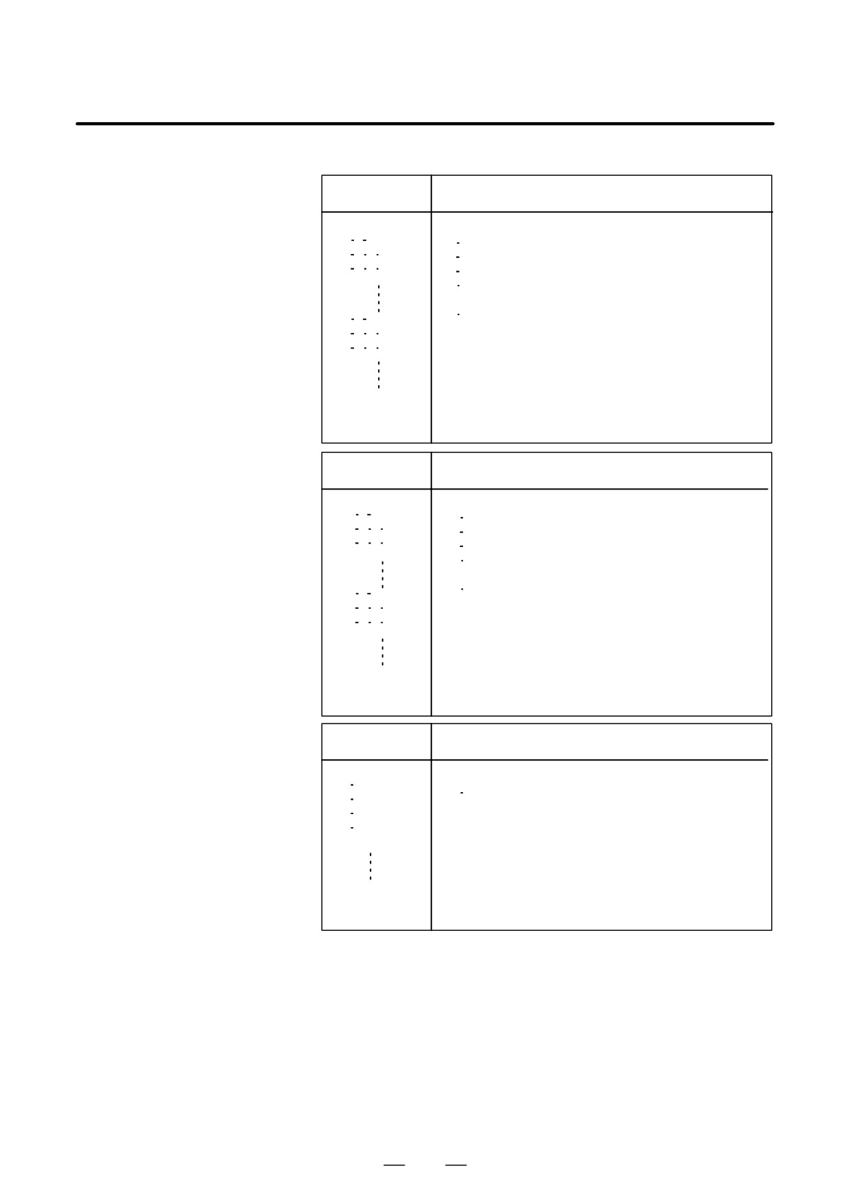
D Register with deleting
Format
Meaning of command
all groups
G10L3 ;
G10L3 :Register with deleting all groups
PL ;
P
:Group number
THD ;
L
:Life value
THD ;
T
:Tool number
H
:Code specifying tool offset value
(H code)
D
:Code specifying tool offset value
PL ;
(D code)
THD ;
G11
:End of registration
THD ;
G11 ;
M02 (M30) ;
D Addition and change of
Format
Meaning of command
tool life management
data
G10L3P1 ;
G10L3P1 :Addition and change of group
PL ;
P
:Group number
THD ;
L
:Life value
THD ;
T
:Tool number
H
:Code specifying tool offset value
(H code)
D
:Code specifying tool offset value
PL ;
(D code)
THD ;
G11
:End of addition and change of
THD ;
group
G11 ;
M02 (M30) ;
D Deletion of tool life
Format
Meaning of command
management data
G10L3P2 ;
G10L3P2 :Deletion of group
P ;
P
:Group number
P ;
G11
:End of deletion of group
P ;
P ;
G11 ;
M02 (M30) ;
115
10. TOOL FUNCTION
(T FUNCTION)
PROGRAMMING
B-64124EN/01
D Setting a tool life cout
Format
Meaning of command
type for groups
G10L3
Q_ : Life count type (1:Frequency, 2:Time)
or
G10L3P1);
PL Q ;
THD ;
⋅
THD ;
⋅
PL Q ;
THD ;
THD ;
G11 ;
M02 (M30) ;
CAUTION
1
When the Q command is omitted, the value set in bit 2 (LTM)
of parameter No.6800 is used as the life count type.
2
G10L3P1 and G10L3L2 can be commanded only when the
extended tool life management feature is enabled.
(Parameter EXT (No.6801#6) = 1)
116
10. TOOL FUNCTION
B-64124EN/01
PROGRAMMING
(T FUNCTION)
10.2.3
Tool Life Management
Command in a
Machining Program
Explanations
D Command
The following command is used for tool life management:
Toooo; Specifies a tool group number.
The tool life management function selects, from a specified group, a
tool whose life has not expired, and outputs its T code. In oooo,
specify a number calculated by adding the tool life management cancel
number specified in parameter6810 to a group number. For example,
to set tool group 1 when the tool life management cancel number is
100, specify T101;.
NOTE
When oooo is less than a tool life management cancel
number, the T code is treated as an ordinary T code.
M06;
Terminates life management for the previously used tools,
and begins counting the life of the new tools selected with
the T code.
WARNING
When an option for speciofying multiple M codes is
selected, specify this code by itself or as the first M code.
H99;
Selects the H code of tool life management data for the tool
currently being used.
H00;
Cancels tool length offset
D99;
Selects the D code of tool life management data for the tool
currently being used.
D00;
Cancels cutter compensation
WARNING
H99 or D99 must be specified after the M06 command.
When a code other than H99 or D99 is specified after the
M06 command, the H code and D code of tool life
management data are not selected.
117
10. TOOL FUNCTION
(T FUNCTION)
PROGRAMMING
B-64124EN/01
D Types
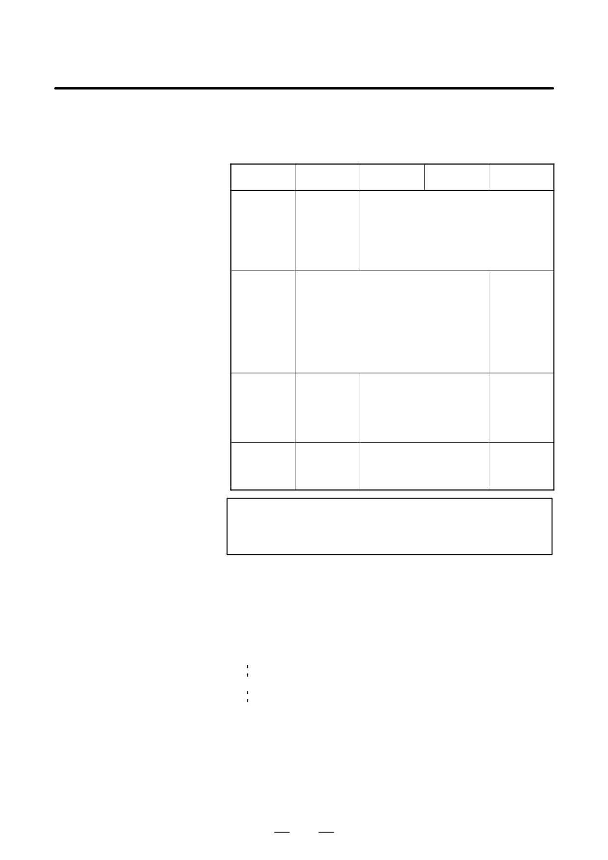
For tool life management, the four tool change types indicated below are
available. The type used varies from one machine to another. For details,
refer to the appropriate manual of each machinde tool builder.
Table 10.2.3 Tool Change Type
Tool change
A
B
C
D
type
Tool group
Previously
Tools to be used next
number spe-
used tools
cified in the
same block
as the tool
change com-
mand (M06)
Tool life count
Life counting is performed for a tool in the
Life counting
timing
specified tool group when M06 is specified
is performed
next.
when a tool
in the tool
group speci-
fied in the
same block
as M06 is
specified.
Remarks
Normally, when a tool group
When only
number is specified by itself,
M06 is speci-
type B is used. However, no
fied, P/S
alarm is raised even if the
alarm No.
tool group number is speci-
153 is
fied by itself as type C.
issued.
Parameter
No. 6800#7
No. 6800#7 (M6T)=1
No.6801#7
(M6T)=0
No. 6801#7 (M6E)=0
(M6E)=1
No.6801#7
(M6E)=0
NOTE
When a tool group number is specified and a new tool is
selected, the new tool selection signal is output.
Examples
D Tool change type A
Suppose that the tool life management cancel number is 100.
T101; A tool whose life has not expired is selected from group 1.
(Suppose that tool number 010 is selected.)
M06; Tool life counting is performed for the tool in group 1.
(The life of tool number 010 is counted.)
T102; A tool whose life has not expired is selected from group 2.
(Suppose that tool number 100 is selected.)
M06T101; Tool life counting is performed for the tool in group 2.
(The life of tool number 100 is counted.)
The number of the tool currently used (in group 1) is
output with a T code signal. (Tool number 010 is
output.)
118
10. TOOL FUNCTION
B-64124EN/01
PROGRAMMING
(T FUNCTION)
D Tool change type B
and C
Suppose that the tool life management ignore number is 100.
T101;
A tool whose life has not expired is selected from group 1.
(Suppose that tool number 010 is selected.)
M06T102;Tool life counting is performed for the tool in group 1.
(The life of tool number 010 is counted.)
A tool whose life has not expired is selected from group 2.
(Suppose that toolnumber 100 is selected.
M06T103;Tool life counting is lperformed for the tool in group 2.
(The life of tool number 100 is counted.)
A tool whose life has not expired is selected from group 3.
(Suppose that tool number 200 is selected.)
D Tool change type D
Suppose that the tool life management ignore number is 100.
T101M06;A tool whose life has not expired is selected from group 1.
(Suppose that tool number 010 is selected.)
Tool life counting is performed for the tool in group 1.
T102M06;A tool whose life has not expired is selected from group 2.
(Suppose that tool number 100 is selected.)
Tool life counting is performed for the tool in group 2.
(The life of tool number 100 is counted.)
119

10. TOOL FUNCTION
(T FUNCTION)
PROGRAMMING
B-64124EN/01
10.2.4
The life of a tool is specified by a usage frequency (count) or usage time
(in minutes).
Tool Life
Explanations
D Usage count
The usage count is incremented by 1 for each tool used in a program.
In other words, the usage count is incremented by 1 only when the first
tool group number and tool change command are specified after the
CNC unit enters the automatic operation state from the reset state.
CAUTION
Even if the same tool group number is specified more than
once in a program, the usage count is only incremented by
1 and no new tools are selected.
D Usage time
When a tool change is specified (M06), tool life management is started
for the tools specified by the tool group number. In tool life
management, the time during which a tool is used in the cutting mode
is counted in four second increments., If the tool group is changed
before the incremental time of four seconds elapses, the time is not
counted. The time a tool is used for single block stop, feed hold, rapid
traverse, dwell, machine lock, and interlock is not counted.
NOTE
1
When a tool is selected from available tools, tools are
searched starting from the current tool towards the lasttool
to find a tool whose life has not expired. When thelast tool
is reached during this search, the search restartsfrom the
first tool. When it has been determined that there are no
tools whose life has not expired, the last tool is selected.
When the tool currently being used is changed by tool skip
signal, the next new tool is selected using the method
described here.
2
When tool life is counted by time, the life counting can be
overridden using the tool life count override signal. An
override from 0 to 99.9 can be applied. When 0 is specified,
time is not counted. Before the override capability can be
used, bit 2 of parameter LFV No.6801 must be set.
3
When tool life counting indicates that the life of the last tool
in a group has expired, the tool change signal is output.
When tool life is managed by time, the signal is output when
the life of the last tool in the group has expired. When tool
life is managed by usage frequency (count), the signal is
output when the CNC unit is reset or the tool life count
restart M code is specified.
120
B-64124EN/01
PROGRAMMING
11. AUXILIARY FUNCTION
AUXILIARY FUNCTION
11
General
There are two types of auxiliary functions ; miscellaneous function (M
code) for specifying spindle start, spindle stop program end, and so on,
and secondary auxiliary function (B code) for specifying index table
positioning.
When a move command and miscellaneous function are specified in the
same block, the commands are executed in one of the following two
ways:
i) Simultaneous execution of the move command and miscellaneous
function commands.
ii) Executing miscellaneous function commands upon completion of
move command execution.
The selection of either sequence depends on the machine tool builder’s
specification. Refer to the manual issued by the machine tool builder for
details.
121
11. AUXILIARY FUNCTION
PROGRAMMING
B-64124EN/01
11.1
When a numeral is specified following address M, code signal and a
strobe signal are sent to the machine. The machine uses these signals to
AUXILIARY
turn on or off its functions.
FUNCTION
Usually, only one M code can be specified in one block. In some cases,
(M FUNCTION)
however, up to three M codes can be specified for some types of machine
tools.
Which M code corresponds to which machine function is determined by
the machine tool builder.
The machine processes all operations specified by M codes except those
specified by M98, M99,M198 or called subprogram(Parameter No.6071
to 6079), or called custom macro (Parameter No.6080 to 6089). Refer to
the machine tool builder’s instruction manual for details.
Explanations
The following M codes have special meanings.
D M02,M03
This indicates the end of the main program
(End of program)
Automatic operation is stopped and the CNC unit is reset.
This differs with the machine tool builder.
After a block specifying the end of the program is executed,
control returns to the start of the program.
Bit 5 of parameter 3404 (M02) or bit 4 of parameter 3404 (M30) can be
used to disable M02, M30 from returning control to the start of the
program.
D M00
Automatic operation is stopped after a block containing M00 is executed.
(Program stop)
When the program is stopped, all existing modal information remains
unchanged. The automatic operation can be restarted by actuating the
cycle operation. This differs with the machine tool builder.
D M01
Similarly to M00, automatic operation is stopped after a block containing
(Optional stop)
M01 is executed. This code is only effective when the Optional Stop
switch on the machine operator’s panel has been pressed.
D M98
This code is used to call a subprogram. The code and strobe signals are
(Calling of sub-
not sent. See the subprogram II- 12.3 for details .
program)
D M99
This code indicates the end of a subprogram.
(End of subprogram)
M99 execution returns control to the main program. The code and strobe
signals are not sent. See the subprogram section 12.3 for details.
D M198 (Calling a
This code is used to call a subprogram of a file in the external input/output
subprogram)
function. See the description of the subprogram call function (III-4.6) for
details.
NOTE
The block following M00, M01, M02, or M30 is not pre-read
(buffered). Similarly, ten M codes which do not buffer can
be set by parameters (Nos. 3411 to 3420). Refer to the
machine tool builder’s instruction manual for these M codes.
122

B-64124EN/01
PROGRAMMING
11. AUXILIARY FUNCTION
In general, only one M code can be specified in a block. However, up to
11.2
three M codes can be specified at once in a block by setting bit 7 (M3B)
MULTIPLE M
of parameter No. 3404 to 1. Up to three M codes specified in a block are
COMMANDS
simultaneously output to the machine. This means that compared with
the conventional method of a single M command in a single block, a
IN A SINGLE BLOCK
shorter cycle time can be realized in machining.
Explanations
CNC allows up to three M codes to be specified in one block.
However, some M codes cannot be specified at the same time due to
mechanical operation restrictions. For detailed information about the
mechanical operation restrictions on simultaneous specification of
multiple M codes in one block, refer to the manual of each machine
tool builder.
M00, M01, M02, M30, M98, M99, or M198 must not be specified
together with another M code.
Some M codes other than M00, M01, M02, M30, M98, M99, and
M198 cannot be specified together with other M codes; each of those
M codes must be specified in a single block.
Such M codes include these which direct the CNC to perform internal
operations in addition to sending the M codes themselves to the
machine. To be specified, such M codes are M codes for calling
program numbers 9001 to 9009 and M codes for disabling advance
reading (buffering) of subsequent blocks. Meanwhile, multiple of M
codes that direct the CNC only to send the M codes themselves
(without performing internal operations ) can be specified in a single
block.
Examples
One M command
Multiple M commands
in a single block
in a single block
M40 ;
M40M50M60 ;
M50 ;
G28G91X0Y0Z0 ;
M60 ;
:
G28G91X0Y0Z0 ;
:
:
:
:
:
:
:
123
11. AUXILIARY FUNCTION
PROGRAMMING
B-64124EN/01
When a value is specified after address B, the code signal and strobe signal
11.3
are output. The code is retained until a B code is specified next.
THE SECOND
The functions are used for machine side operations such as indexing for
AUXILIARY
the rotation axis. Each block can contain only one B code. Setting
parameter No. 3460 enables the use of one of addresses A, C, V, and W,
FUNCTIONS
instead of address B. However, this address must be different from that
(B CODES)
for the controlled axis. For details, refer to the manual issued by the
machine tool builder.
Explanations
D Valid data range
0 to 99999999
D Specification
1. To enable the use of a decimal point, set bit 0 (AUP) of parameter
No.3450 to 1.
Command Output value
B10.
10000
B10
10
2. Use bit 0 (DPI) of parameter No. 3401 to specify whether the
magnification for B output will be
1000 or
1 when a decimal
point is omitted.
Command Output value
DPI=1
B1
1000
DPI=0
B1
1
3. Use bit 0 (AUX) of parameter No. 3405 to specify whether the
magnification for B output will be
1000 or
10000 when a
decimal point is omitted for the inch Input system
(only when DPI=1).
Command Output value
AUX=1
B1
10000
AUX=0
B1
1000
Restrictions
The address (B or the address specified with parameter No. 3460) used
with the second auxiliary functions cannot be used for the controlled axis
name (parameter No. 1020).
124
B-64124EN/01
PROGRAMMING
12. PROGRAM CONFIGURATION
PROGRAM CONFIGURATION
12
General
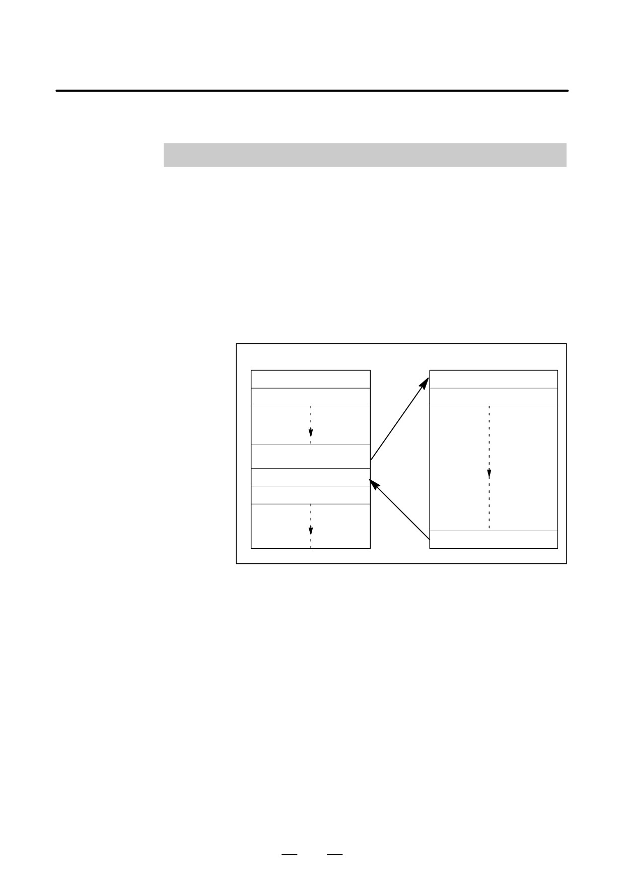
D Main program and
There are two program types, main program and subprogram. Normally,
subprogram
the CNC operates according to the main program. However, when a
command calling a subprogram is encountered in the main program,
control is passed to the subprogram. When a command specifying a
return to the main program is encountered in a subprogram, control is
returned to the main program.
Main program
Subprogram
Instruction 1
Instruction 1Ȁ
Instruction 2
Instruction 2Ȁ
Follow the direction of the
subprogram
Instruction n
Instruction n+1
Return to the main program
Fig. 12 (a) Main program and subprogram
The CNC memory can hold up to 400 main programs and subprograms.
A main program can be selected from the stored main programs to operate
the machine. See III-9.3 or III-10 in OPERATION for the methods of
registering and selecting programs.
125
12. PROGRAM CONFIGURATION
PROGRAMMING
B-64124EN/01
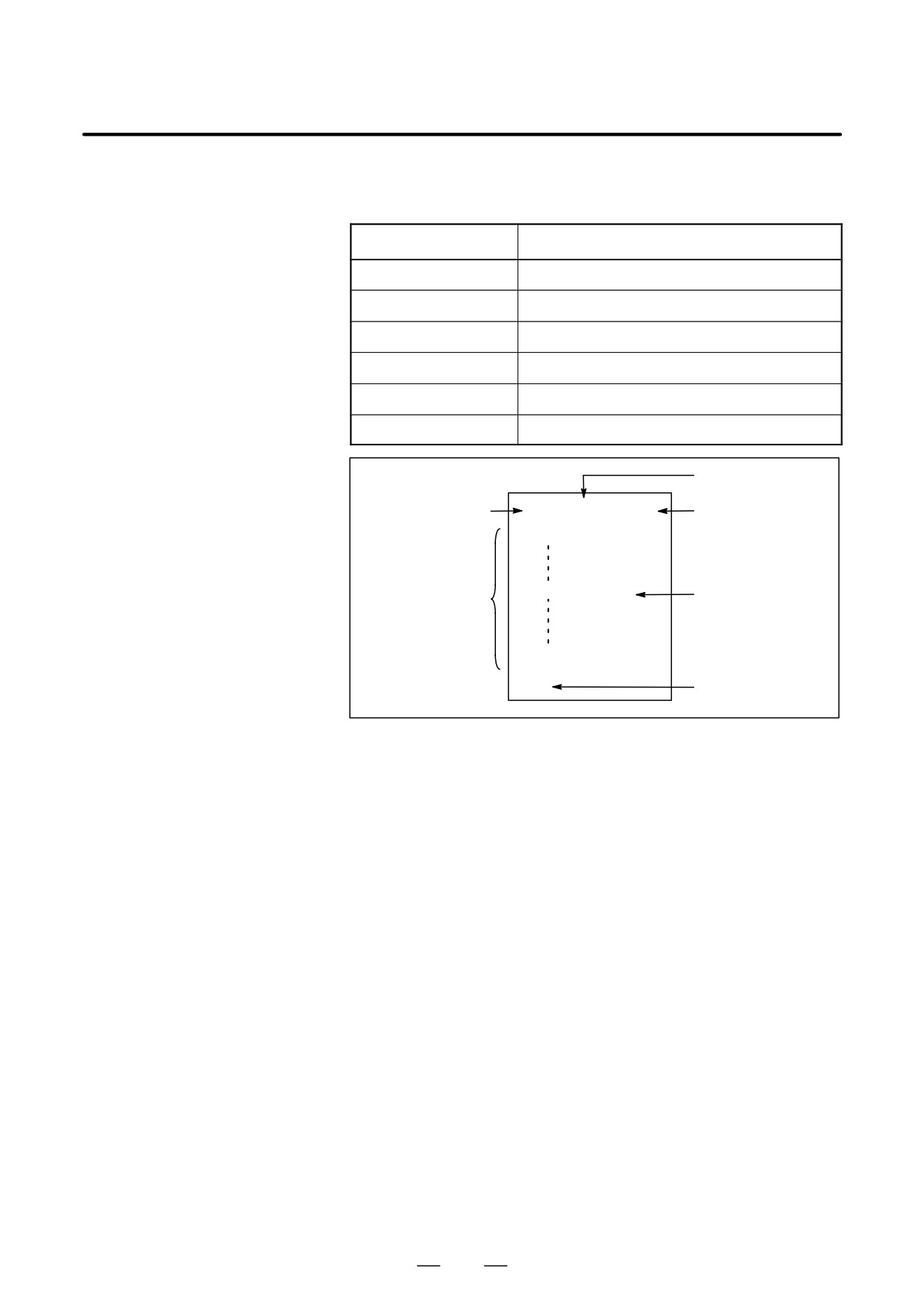
D Program components
A program consists of the following components:
Table 12 Program components
Components
Descriptions
Tape start
Symbol indicating the start of a program file
Leader section
Used for the title of a program file, etc.
Program start
Symbol indicating the start of a program
Program section
Commands for machining
Comment section
Comments or directions for the operator
Tape end
Symbol indicating the end of a program file
Leader section
Tape start
% TITLE
;
Program start
O0001 ;
(COMMENT)
Program section
Comment section
M30 ;
%
Tape end
Fig. 12 (b) Program configuration
D Program section
A program section consists of several blocks. A program section starts
configuration
with a program number and ends with a program end code.
Program section
Program section
configuration
Program number
O0001 ;
Block 1
N1 G91 G00 X120.0 Y80.0 ;
Block 2
N2 G43 Z-32.0 H01 ;
:
:
Block n
Nn Z0 ;
Program end
M30 ;
A block contains information necessary for machining, such as a move
command or coolant on/off command.Specifying a slash (/) at the start
of a block disables the execution of some blocks (see “optional block
skip” in II-12.2).
126
B-64124EN/01
PROGRAMMING
12. PROGRAM CONFIGURATION
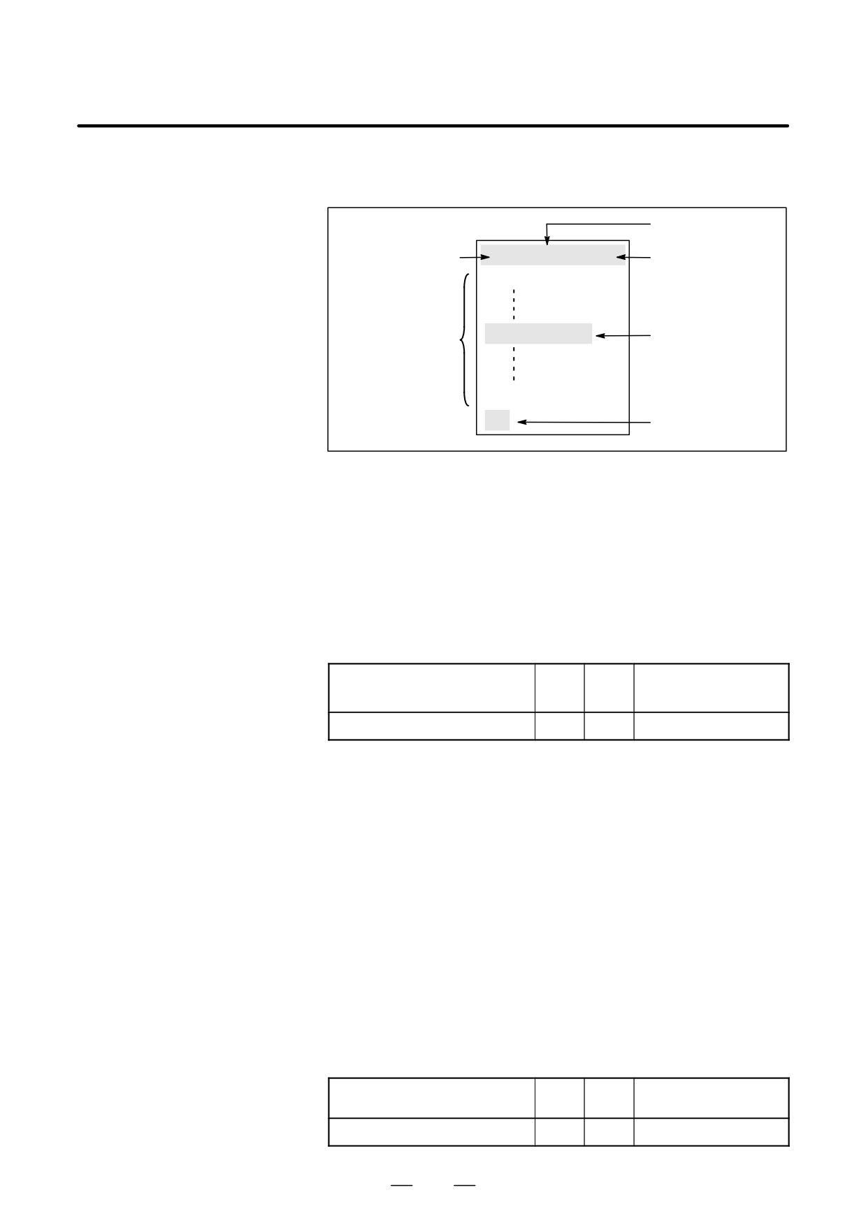
This section describes program components other than program sections.
12.1
See II-12.2 for a program section.
PROGRAM
COMPONENTS
Leader section
OTHER THAN
Tape start
% TITLE
;
Program start
PROGRAM
O0001 ;
SECTIONS
(COMMENT)
Comment section
Program section
M30 ;
%
Tape end
Fig. 12.1 (a) Program configuration
Explanations
D Tape start
The tape start indicates the start of a file that contains NC programs.
The mark is not required when programs are entered using SYSTEM P
or ordinary personal computers. The mark is not displayed on the screen.
However, if the file is output,the mark is automatically output at the start
of the file.
Table 12.1 (a) Code of a tape start
Name
ISO
EIA
Notation in this manual
code
code
Tape start
%
ER
%
D Leader section
Data entered before the programs in a file constitutes a leader section.
When machining is started, the label skip state is usually set by turning
on the power or resetting the system. In the label skip state, all
information is ignored until the first end-of-block code is read. When a
file is read into the CNC unit from an I/O device, leader sections are
skipped by the label skip function.
A leader section generally contains information such as a file header.
When a leader section is skipped, even a TV parity check is not made. So
a leader section can contain any codes except the EOB code.
D Program start
The program start code is to be entered immediately after a leader section,
that is, immediately before a program section.
This code indicates the start of a program, and is always required to
disable the label skip function.
With SYSTEM P or ordinary personal computers, this code can be entered
by pressing the return key.
Table 12.1 (b) Code of a program start
Name
ISO
EIA
Notation in this manual
code
code
Program start
LF
CR
;
127
12. PROGRAM CONFIGURATION
PROGRAMMING
B-64124EN/01
NOTE
If one file contains multiple programs, the EOB code for
label skip operation must not appear before a second or
subsequent program number.
D Comment section
Any information enclosed by the control-out and control-in codes is
regarded as a comment.
The user can enter a header, comments, directions to the operator, etc. in
a comment section.
Table 12.1 (c) Codes of a control-in and a control-out
Name
ISO
EIA
Notation in this
Meaning
code
code
manual
Control-out
(
2-4-5
(
Start of comment section
Control-in
)
2-4-7
)
End of comment section
When a program is read into memory for memory operation, comment
sections, if any, are not ignored but are also read into memory. Note,
however, that codes other than those listed in the code table in Appendix
A are ignored, and thus are not read into memory.
When data in memory is output on external I/O device(See III-8), the
comment sections are also output.
When a program is displayed on the screen, its comment sections are also
displayed. However, those codes that were ignored when read into
memory are not output or displayed.
During memory operation or DNC operation, all comment sections are
ignored.
The TV check function can be used for a comment section by setting
parameter CTV (bit 1 of No. 0100).
CAUTION
If a long comment section appears in the middle of a
program section, a move along an axis may be suspended
for a long time because of such a comment section. So a
comment section should be placed where movement
suspension may occur or no movement is involved.
NOTE
1
If only a control-in code is read with no matching
control-out code, the read control-in code is ignored.
2
The EOB code cannot be used in a comment.
128
B-64124EN/01
PROGRAMMING
12. PROGRAM CONFIGURATION
D Tape end
A tape end is to be placed at the end of a file containing NC programs.
If programs are entered using the automatic programming system, the
mark need not be entered.
The mark is not displayed on the screen. However, when a file is output,
the mark is automatically output at the end of the file.
If an attempt is made to execute % when M02 or M03 is not placed at the
end of the program, the P/S alarm (No. 5010) is occurred.
Table 12.1 (d) Code of a tape end
Name
ISO
EIA
Notation in this
code
code
manual
Tape end
%
ER
%
129
12. PROGRAM CONFIGURATION
PROGRAMMING
B-64124EN/01
This section describes elements of a program section. See II-12.1 for
12.2
program components other than program sections.
PROGRAM SECTION
CONFIGURATION
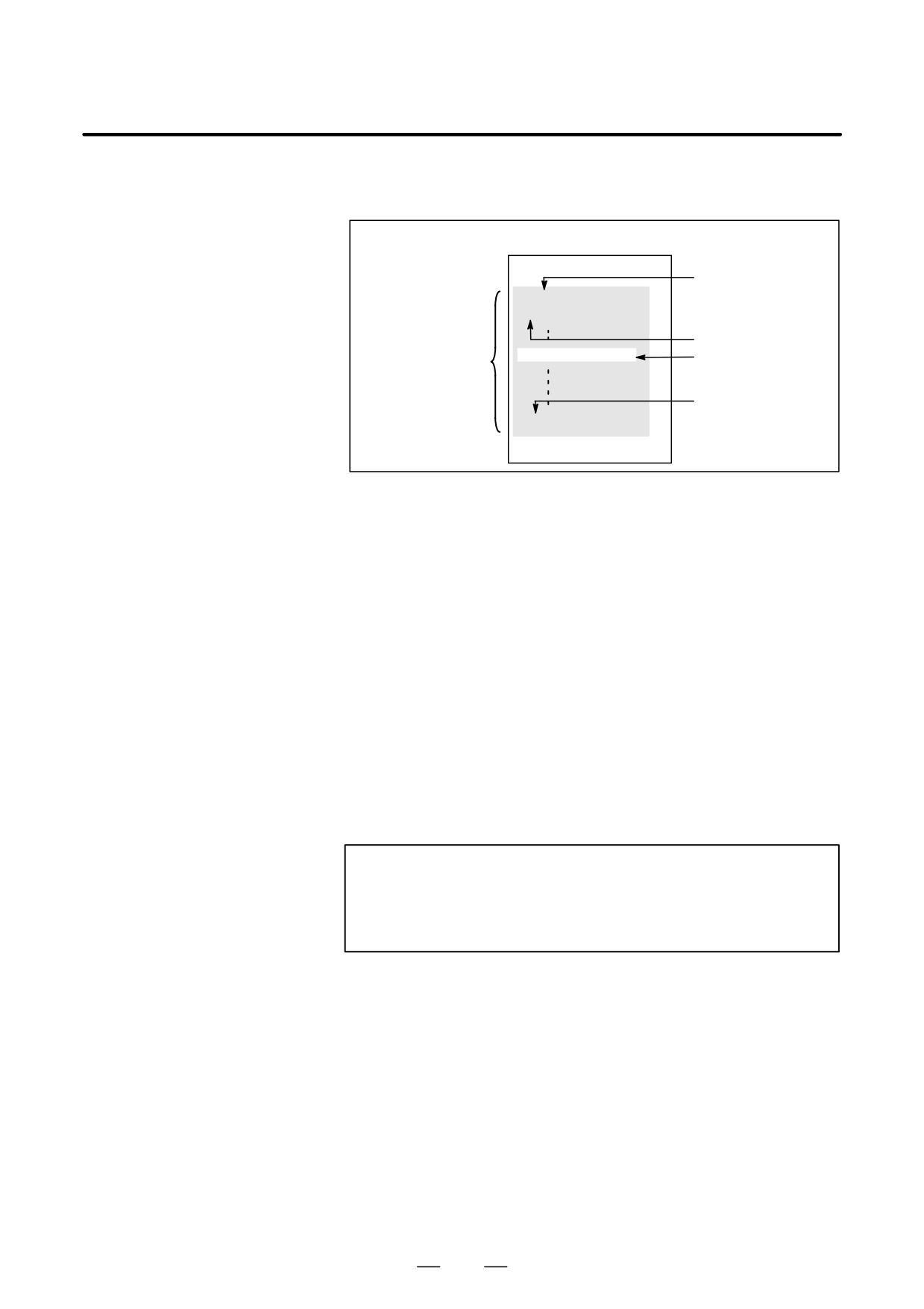
% TITLE;
Program number
O0001 ;
N1 … ;
Sequence number
(COMMENT)
Comment section
Program section
Program end
M30 ;
%
Fig. 12.2 (a) Program configuration
D Program number
A program number consisting of address O followed by a four-digit
number is assigned to each program at the beginning registered in
memory to identify the program.
In ISO code, the colon ( : ) can be used instead of O.
When no program number is specified at the start of a program, the
sequence number (N
) at the start of the program is regarded as its
program number. If a five-digit sequence number is used, the lower four
digits are registered as a program number. If the lower four digits are all
0, the program number registered immediately before added to 1 is
registered as a program number. Note, however, that N0 cannot be used
for a program number.
If there is no program number or sequence number at the start of a
program, a program number must be specified using the MDI panel when
the program is stored in memory (See III-8.4 or III-10.1)
NOTE
Program numbers 8000 to 9999 may be used by machine
tool builders, and the user may not be able to use these
numbers.
130
B-64124EN/01
PROGRAMMING
12. PROGRAM CONFIGURATION
D Sequence number and
A program consists of several commands. One command unit is called a
block
block. One block is separated from another with an EOB of end of block
code.
Table 12.2 (a) EOB code
Name
ISO
EIA
Notation in this
code
code
manual
End of block (EOB)
LF
CR
;
At the head of a block, a sequence number consisting of address N
followed by a number not longer than five digits (1 to 99999) can be
placed. Sequence numbers can be specified in a random order, and any
numbers can be skipped. Sequence numbers may be specified for all
blocks or only for desired blocks of the program. In general, however, it
is convenient to assign sequence numbers in ascending order in phase
with the machining steps (for example, when a new tool is used by tool
replacement, and machining proceeds to a new surface with table
indexing.)
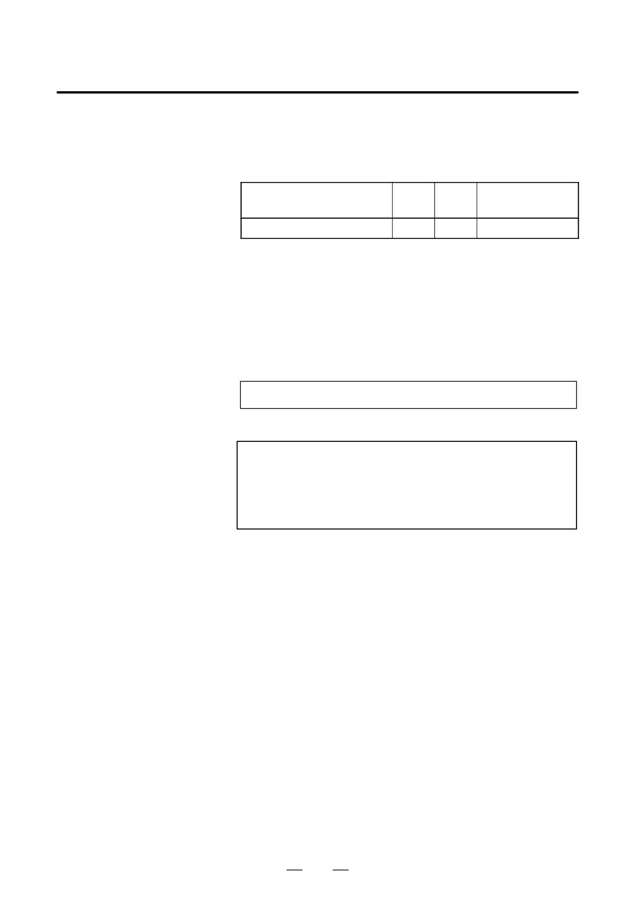
N300 X200.0 Z300.0 ; A sequence number is underlined.
Fig. 12.2 (b) Sequence number and block (example)
NOTE
N0 must not be used for the reason of file compatibility with
other CNC systems.
Program number 0 cannot be used. So 0 must not be used
for a sequence number regarded as a program number.
D TV check (Vertical parity
A parity check is made for a block on input tape vertically. If the number
check along tape)
of characters in one block (starting with the code immediately after an
EOB and ending with the next EOB) is odd, an P/S alarm (No.002) is
output. No TV check is made only for those parts that are skipped by the
label skip function. Bit 1 (CTV) of parameter No. 0100 is used to specify
whether comments enclosed in parentheses are counted as characters
during TV check. The TV check function can be enabled or disabled by
setting on the MDI unit (See III-11.4.3.).
131
12. PROGRAM CONFIGURATION
PROGRAMMING
B-64124EN/01
D Block configuration
A block consists of one or more words. A word consists of an address
(word and address)
followed by a number some digits long. (The plus sign (+) or minus sign
(-) may be prefixed to a number.)
Word = Address + number (Example : X-1000)
For an address, one of the letters (A to Z) is used ; an address defines the
meaning of a number that follows the address. Table 12.2 (b) indicates
the usable addresses and their meanings.
The same address may have different meanings, depending on the
preparatory function specification.
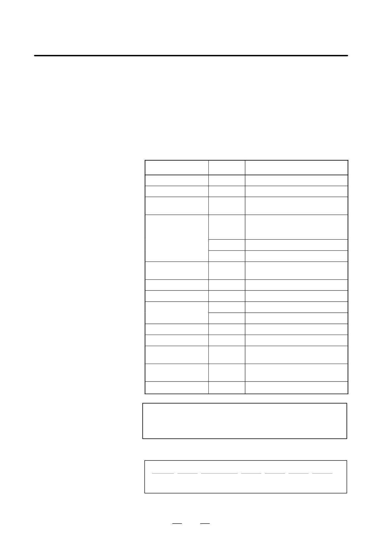
Table 12.2 (b) Major functions and addresses
Function
Address
Meaning
Program number
O (1)
Program number
Sequence number
N
Sequence number
Preparatory function
G
Specifies a motion mode (linear, arc,
etc.)
Dimension word
X, Y, Z, U,
Coordinate axis move command
V, W, A, B,
C
I, J, K
Coordinate of the arc center
R
Arc radius
Feed function
F
Rate of feed per minute,
Rate of feed per revolution
Spindle speed function
S
Spindle speed
Tool function
T
Tool number
Auxiliary function
M
On/off control on the machine tool
B
Table indexing, etc.
Offset number
D, H
Offset number
Dwell
P, X
Dwell time
Program number
P
Subprogram number
designation
Number of
P
Number of subprogram repetitions
repetitions
Parameter
P, Q
Canned cycle parameter
NOTE
In ISO code, the colon ( : ) can also be used as the address
of a program number.
N_
G_
X_ Y_
F_
S_
T_
M_
;
Spindle
Sequence Preparatory
Dimension Feed-
Tool
Miscellaneous
speed
number
function
word
function
function
function
function
Fig. 12.2 (c) 1 block (example)
132