FANUC Series 0i-MC. OPERATOR’S MANUAL - page 3
B-64124EN/01
PROGRAMMING
4. INTERPOLATION FUNCTIONS
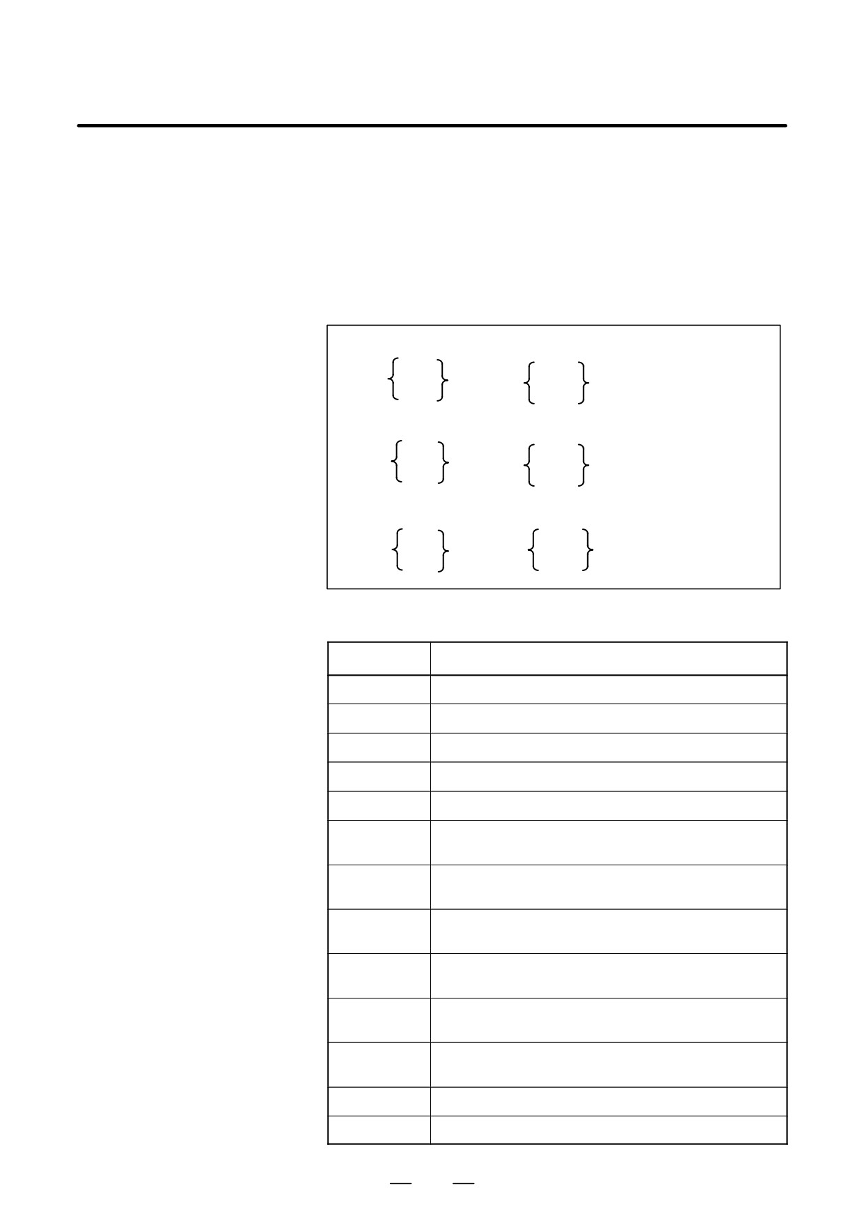
The command below will move a tool along a circular arc.
4.4
CIRCULAR
INTERPOLATION
(G02,G03)
Format
Arc in the XpYp plane
G02
I_ J_
G17
Xp_Yp_
F_ ;
G03
R_
Arc in the ZpXp plane
G02
I_ K_
G18
Xp_ p_
F_
G03
R_
Arc in the YpZp plane
G02
J_ K_
F_
G19
Yp_ Zp_
G03
R_
Table 4.4 Description of the command format
Command
Description
G17
Specification of arc on XpYp plane
G18
Specification of arc on ZpXp plane
G19
Specification of arc on YpZp plane
G02
Circular Interpolation Clockwise direction (CW)
G03
Circular Interpolation Counterclockwise direction (CCW)
Xp_
Command values of X axis or its parallel axis
(set by parameter No. 1022)
Yp_
Command values of Y axis or its parallel axis
(set by parameter No. 1022)
Zp_
Command values of Z axis or its parallel axis
(set by parameter No. 1022)
I_
Xp axis distance from the start point to the center of an arc
with sign
J_
Yp axis distance from the start point to the center of an arc
with sign
k_
Zp axis distance from the start point to the center of an arc
with sign
R_
Arc radius (with sign)
F_
Feedrate along the arc
43
4. INTERPOLATION FUNCTIONS
PROGRAMMING
B-64124EN/01
Explanations
D Direction of the circular
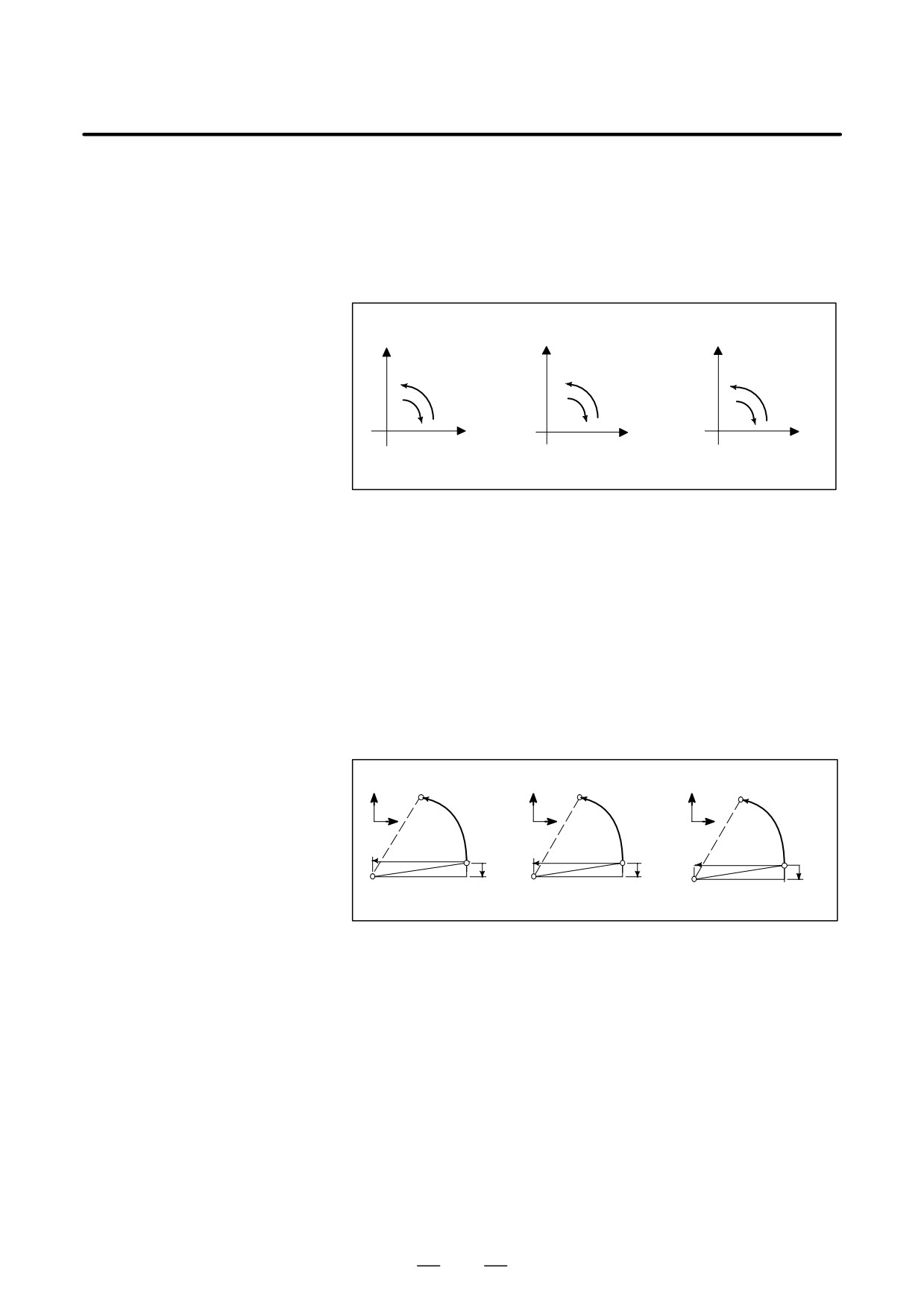
“Clockwise”(G02) and “counterclockwise”(G03) on the XpYp plane
interpolation
(ZpXp plane or YpZp plane) are defined when the XpYp plane is viewed
in the positive-to-negative direction of the Zp axis (Yp axis or Xp axis,
respectively) in the Cartesian coordinate system. See the figure below.
Yp
Xp
Zp
G03
G03
G03
G02
G02
G02
Xp
Zp
Yp
G17
G18
G19
D Distance moved on an
The end point of an arc is specified by address Xp, Yp or Zp, and is
arc
expressed as an absolute or incremental value according to G90 or G91.
For the incremental value, the distance of the end point which is viewed
from the start point of the arc is specified.
D Distance from the start
The arc center is specified by addresses I, J, and K for the Xp, Yp, and Zp
point to the center of arc
axes, respectively. The numerical value following I, J, or K, however, is
a vector component in which the arc center is seen from the start point,
and is always specified as an incremental value irrespective of G90 and
G91, as shown below.
I, J, and K must be signed according to the direction.
End point (x,y)
End point (z,x)
End point (y,z)
y
x
z
x
Start
z
y
i
Start
j
Start
k
point
point
point
j
i
k
Center
Center
Center
I0,J0, and K0 can be omitted. When Xp, Yp , and Zp are omitted (the end
point is the same as the start point) and the center is specified with I, J,
and K, a 360° arc (circle) is specified.
G021; Command for a circle
If the difference between the radius at the start point and that at the
end point exceeds the permitted value in a parameter (No.3410), an P/S
alarm (No.020) occurs.
44
B-64124EN/01
PROGRAMMING
4. INTERPOLATION FUNCTIONS
D Arc radius
The distance between an arc and the center of a circle that contains the arc
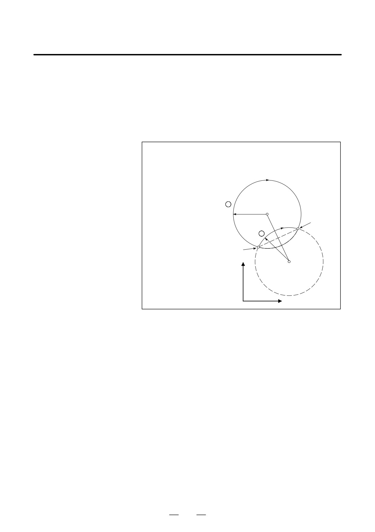
can be specified using the radius, R, of the circle instead of I, J, and K.
In this case, one arc is less than 180°, and the other is more than 180° are
considered. When an arc exceeding 180° is commanded, the radius must
be specified with a negative value. If Xp, Yp, and Zp are all omitted, if
the end point is located at the same position as the start point and when
R is used, an arc of 0° is programmed
G02R ; (The cutter does not move.)
For arc (1)(less than 180°)
G91 G02 XP60.0 YP20.0 R50.0 F300.0 ;
For arc (2)(greater than 180°)
G91 G02 XP60.0 YP20.0 R-50.0 F300.0 ;
2
r=50mm
End point
1
Start point
r=50mm
Y
X
D Feedrate
The feedrate in circular interpolation is equal to the feed rate specified by
the F code, and the feedrate along the arc (the tangential feedrate of the
arc) is controlled to be the specified feedrate.
The error between the specified feedrate and the actual tool feedrate is
±2% or less. However, this feed rate is measured along the arc after the
cutter compensation is applied
Restrictions
If I, J, K, and R addresses are specified simultaneously, the arc specified
by address R takes precedence and the other are ignored.
If an axis not comprising the specified plane is commanded, an alarm is
displayed.
For example, if axis U is specified as a parallel axis to X axis when plane
XY is specified, an P/S alarm (No.028)is displayed.
When an arc having a center angle approaching 180° is specified, the
calculated center coordinates may contain an error. In such a case, specify
the center of the arc with I, J, and K.
45
4. INTERPOLATION FUNCTIONS
PROGRAMMING
B-64124EN/01
Examples
Y axis
100
50R
60
60R
40
0
X axis
90
120 140
200
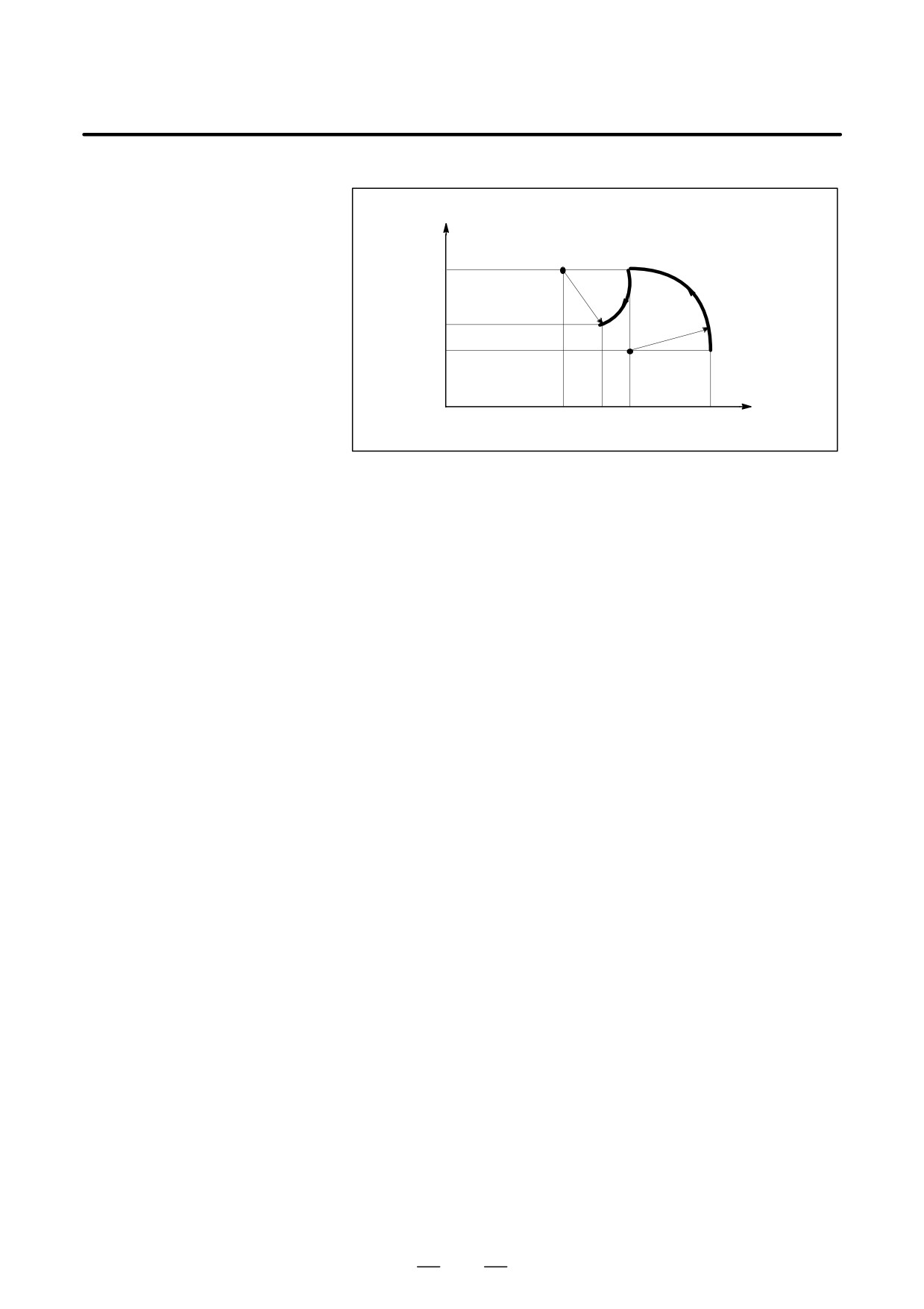
The above tool path can be programmed as follows ;
(1) In absolute programming
G92X200.0 Y40.0 Z0 ;
G90 G03 X140.0 Y100.0R60.0 F300.;
G02 X120.0 Y60.0R50.0 ;
or
G92X200.0 Y40.0Z0 ;
G90 G03 X140.0 Y100.0I-60.0 F300.;
G02 X120.0 Y60.0I-50.0 ;
(2) In incremental programming
G91 G03 X-60.0 Y60.0 R60.0 F300.;
G02 X-20.0 Y-40.0 R50.0 ;
or
G91 G03 X-60.0 Y60.0 I-60.0 F300. ;
G02 X-20.0 Y-40.0 I-50.0 ;
46
B-64124EN/01
PROGRAMMING
4. INTERPOLATION FUNCTIONS
4.5
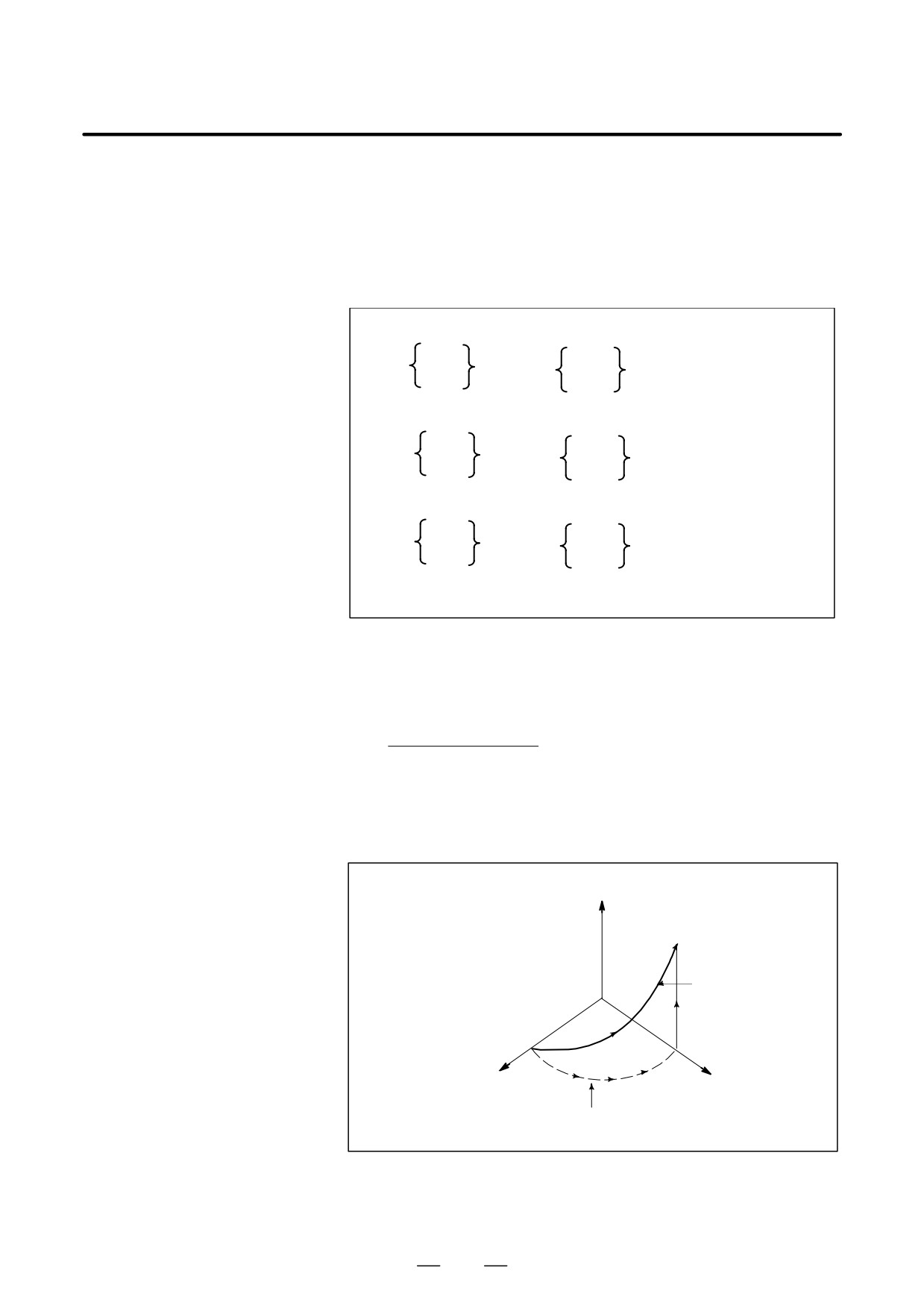
Helical interpolation which moved helically is enabled by specifying up
HELICAL
to two other axes which move synchronously with the circular
INTERPOLATION
interpolation by circular commands.
(G02,G03)
Format
Synchronously with arc of XpYp plane
G02
G17
I_J_
Xp_Yp_
α_(β_)F_;
G03
R_
Synchronously with arc of ZpXp plane
G02
G18
I_K_
Xp_Zp_
α_(β_)F_;
G03
R_
Synchronously with arc of YpZp plane
G02
J_K_
G19
Yp_Zp_
α_(β_)F_;
G03
R_
α,β: Any one axis where circular interpolation is not applied.
Up to two other axes can be specified.
Explanations
The command method is to simply or secondary add a move command
axis which is not circular interpolation axes. An F command specifies a
feed rate along a circular arc. Therefore, the feed rate of the linear axis
is as follows:
Length of linear axis
F×
Length of circular arc
Determine the feed rate so the linear axis feed rate does not exceed any
of the various limit values.Bit 0 (HFC) of parameter No. 1404 can be used
to prevent the linear axis feedrate from exceeding various limit values.
Z
Tool path
X
Y
The feedrate along the circumference of two cir-
cular interpolated axes is the specified feedrate.
Restrictions
Cutter compensation is applied only for a circular arc.
Tool offset and tool length compensation cannot be used in a block in
which a helical interpolation is commanded.
47

4. INTERPOLATION FUNCTIONS
PROGRAMMING
B-64124EN/01
The amount of travel of a rotary axis specified by an angle is once
4.6
internally converted to a distance of a linear axis along the outer surface
CYLINDRICAL
so that linear interpolation or circular interpolation can be performed with
INTERPOLATION
another axis. After interpolation, such a distance is converted back to the
amount of travel of the rotary axis.
(G07.1)
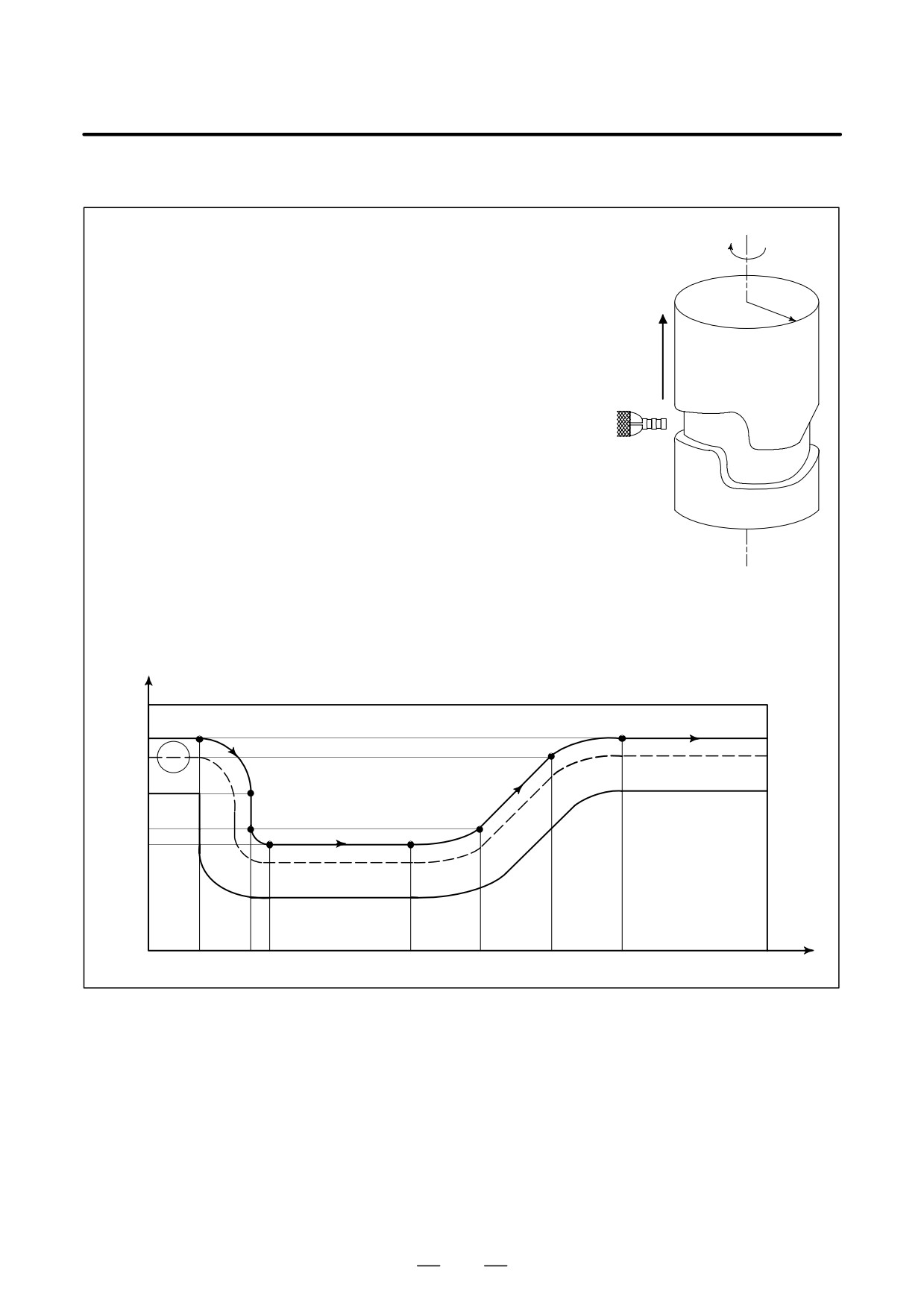
The cylindrical interpolation function allows the side of a cylinder to be
developed for programming. So programs such as a program for
cylindrical cam grooving can be created very easily.
Format
G07.1IPr ; Starts the cylindrical interpolation mode
(e
:
:
:
G07.1
IP
0 ; The cylindrical interpolation mode is cancelled.
IP
: An address for the rotation axis
r : The radius of the cylinder
Specify G07.1 IPr ; and G07.1
IP
0; in separate blocks.
G107 can be used instead of G07.1.
Explanations
D Plane selection
Use parameter (No. 1022) to specify whether the rotation axis is the X-,
(G17, G18, G19)
Y-, or Z-axis, or an axis parallel to one of these axes. Specify the G code
to select a plane for which the rotation axis is the specified linear axis.
For example, when the rotation axis is an axis parallel to the X-axis, G17
must specify an Xp-Yp plane, which is a plane defined by the rotation axis
and the Y-axis or an axis parallel to the Y-axis.
Only one rotation axis can be set for cylindrical interpolation.
D Feedrate
A feedrate specified in the cylindrical interpolation mode is a speed on the
developed cylindrical surface.
D Circular interpolation
In the cylindrical interpolation mode, circular interpolation is possible
(G02,G03)
with the rotation axis and another linear axis. Radius R is used in
commands in the same way as described in II-4.4.
The unit for a radius is not degrees but millimeters (for metric input) or
inches (for inch input).
< Example Circular interpolation between the Z axis and C axis >
For the C axis of parameter (No.1022), 5 (axis parallel with the X axis)
is to be set. In this case, the command for circular interpolation is
G18 Z__C__;
G02 (G03) Z__C__R__;
For the C axis of parameter (No.1022), 6 (axis parallel with the Y axis)
may be specified instead. In this case, however, the command for
circular interpolation is
G19 C__Z__;
G02 (G03) Z__C__R__;
48
B-64124EN/01
PROGRAMMING
4. INTERPOLATION FUNCTIONS
D Tool offset
To perform tool offset in the cylindrical interpolation mode, cancel any
ongoing cutter compensation mode before entering the cylindrical
interpolation mode. Then, start and terminate tool offset within the
cylindrical interpolation mode.
D Cylindrical interpolation
In the cylindrical interpolation mode, the amount of travel of a rotary axis
accuracy
specified by an angle is once internally converted to a distance of a linear
axis on the outer surface so that linear interpolation or circular
interpolation can be performed with another axis. After interpolation,
such a distance is converted back to an angle. For this conversion, the
amount of travel is rounded to a least input increment.
So when the radius of a cylinder is small, the actual amount of travel can
differ from a specified amount of travel. Note, however, that such an error
is not accumulative.
If manual operation is performed in the cylindrical interpolation mode
with manual absolute on, an error can occur for the reason described
above.
MOTION REV
2×2πR
The actual amount
Specified value
=
of travel
2×2πR
MOTION REV
MOTION REV : The amount of travel per rotation of the rotation axis (Set-
ting value of parameter No. 1260)
R
:
Workpiece radius
:Rounded to the least input increment
Limitations
D Arc radius specification
In the cylindrical interpolation mode, an arc radius cannot be specified
in the cylindrical
with word address I, J, or K.
interpolation mode
D Circular interpolation
If the cylindrical interpolation mode is started when cutter compensation
and cutter compensation
is already applied, circular interpolation is not correctly performed in the
cylindrical interpolation mode.
D Positioning
In the cylindrical interpolation mode, positioning operations (including
those that produce rapid traverse cycles such as G28, G53, G73, G74,
G76, G80 through G89) cannot be specified. Before positioning can be
specified, the cylindrical interpolation mode must be cancelled.
Cylindrical interpolation (G07.1) cannot be performed in the positioning
mode (G00).
D Coordinate system
In the cylindrical interpolation mode, a workpiece coordinate system
setting
(G92, G54 through G59) or local coordinate system (G52) cannot be
specified.
D Cylindrical interpolation
In the cylindrical interpolation mode, the cylindrical interpolation mode
mode setting
cannot be reset. The cylindrical interpolation mode must be cancelled
before the cylindrical interpolation mode can be reset.
D Tool offset
A tool offset must be specified before the cylindrical interpolation mode
is set. No offset can be changed in the cylindrical interpolation mode.
D Index table indexing
Cylindrical interpolation cannot be specified when the index table index
function
function is being used.
49
4. INTERPOLATION FUNCTIONS
PROGRAMMING
B-64124EN/01
Examples
Example of a Cylindrical Interpolation Program
C
O0001 (CYLINDRICAL INTERPOLATION );
N01 G00 G90 Z100.0 C0 ;
Z
R
N02 G01 G91 G18 Z0 C0 ;
N03 G07.1 C57299 ;
N04 G90 G01 G42 Z120.0 D01 F250 ;
N05 C30.0 ;
N06 G03 Z90.0 C60.0 R30.0 ;
N07 G01 Z70.0 ;
N08 G02 Z60.0 C70.0 R10.0 ;
N09 G01 C150.0 ;
N10 G02 Z70.0 C190.0 R75.0 ;
N11 G01 Z110.0 C230.0 ;
N12 G03 Z120.0 C270.0 R75.0 ;
N13 G01 C360.0 ;
N14 G40 Z100.0 ;
N15 G07.1 C0 ;
N16 M30 ;
Z
mm
N05
N13
N12
120
110
N06
N11
90
N07
70
N08
N09
N10
60
C
0
30
60
70
150
190
230
270
360
deg
50
B-64124EN/01
PROGRAMMING
4. INTERPOLATION FUNCTIONS
Straight threads with a constant lead can be cut. The position coder
4.7
mounted on the spindle reads the spindle speed in real-time. The read
THREAD CUTTING
spindle speed is converted to the feedrate per minute to feed the tool.
(G33)
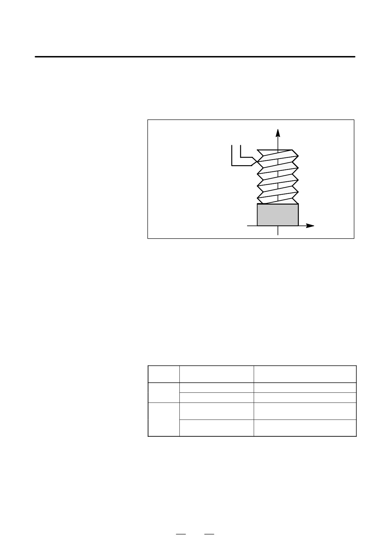
Format
Z
G33
IP
_ F_ ;
F : Long axis direction lead
Workpiece
X
Explanations
In general, thread cutting is repeated along the same tool path in rough
cutting through finish cutting for a screw. Since thread cutting starts when
the position coder mounted on the spindle outputs a 1-turn signal,
threading is started at a fixed point and the tool path on the workpiece is
unchanged for repeated thread cutting. Note that the spindle speed must
remain constant from rough cutting through finish cutting. If not,
incorrect thread lead will occur.
In general, the lag of the servo system, etc. will produce somewhat
incorrect leads at the starting and ending points of a thread cut. To
compensate for this, a thread cutting length somewhat longer than
required should be specified.
Table 4.7 lists the ranges for specifying the thread lead.
Table. 4.7 Ranges of lead sizes that can be specified
Least command
Command value range of the lead
increment
0.001 mm
F1 to F50000 (0.01 to 500.00mm)
mm input
0.0001 mm
F1 to F50000 (0.01 to 500.00mm)
0.0001 inch
F1 to F99999
(0.0001 to 9.9999inch)
Inch input
0.00001 inch
F1 to F99999
(0.0001 to 9.9999inch)
51
4. INTERPOLATION FUNCTIONS
PROGRAMMING
B-64124EN/01
NOTE
1
The spindle speed is limited as follows :
Maximum feedrate
1 x spindle speed x
Thread lead
Spindle speed : min-1
Thread lead : mm or inch
Maximum feedrate : mm/min or inch/min ; maximum command-specified feedrate for
feed-per-minute mode or maximum feedrate that is determined based on mechanical
restrictions including those related to motors, whichever is smaller
2
Cutting feedrate override is not applied to the converted feedrate in all machining process from
rough cutting to finish cutting. The feedrate is fixed at 100%
3
The converted feedrate is limited by the upper feedrate specified.
4
Feed hold is disabled during threading. Pressing the feed hold key during thread cutting causes
the machine to stop at the end point of the next block after threading (that is, after the G33 mode
is terminated)
Examples
Thread cutting at a pitch of 1.5mm
G33 Z10. F1.5;
52

B-64124EN/01
PROGRAMMING
4. INTERPOLATION FUNCTIONS
Linear interpolation can be commanded by specifying axial move
4.8
following the G31 command, like G01. If an external skip signal is input
SKIP
during the execution of this command, execution of the command is
FUNCTION(G31)
interrupted and the next block is executed.
The skip function is used when the end of machining is not programmed
but specified with a signal from the machine, for example, in grinding. It
is used also for measuring the dimensions of a workpiece.
Format
G31
_ ;
IP
G31: One-shot G code (If is effective only in the block in which it
is specified)
Explanations
The coordinate values when the skip signal is turned on can be used in a
custom macro because they are stored in the custom macro system
variable #5061 to #5064, as follows:
#5061 1st axis coordinate value
#5062 2nd axis coordinate value
#5063 3rd axis coordinate value
#5064 4th axis coordinate value
WARNING
Disable feedrate override, dry run, and automatic
acceleration/deceleration
(however, these become
available by setting the parameter SKF No.6200#7 to 1.)
when the feedrate per minute is specified, allowing for an
error in the position of the tool when a skip signal is input.
These functions are enabled when the feedrate per rotation
is specified.
NOTE
If G31 command is issued while cutter compensation C is
applied, an P/S alarm of No.035 is displayed. Cancel the
cutter compensation with the G40 command before the G31
command is specified.
53
4. INTERPOLATION FUNCTIONS
PROGRAMMING
B-64124EN/01
Examples
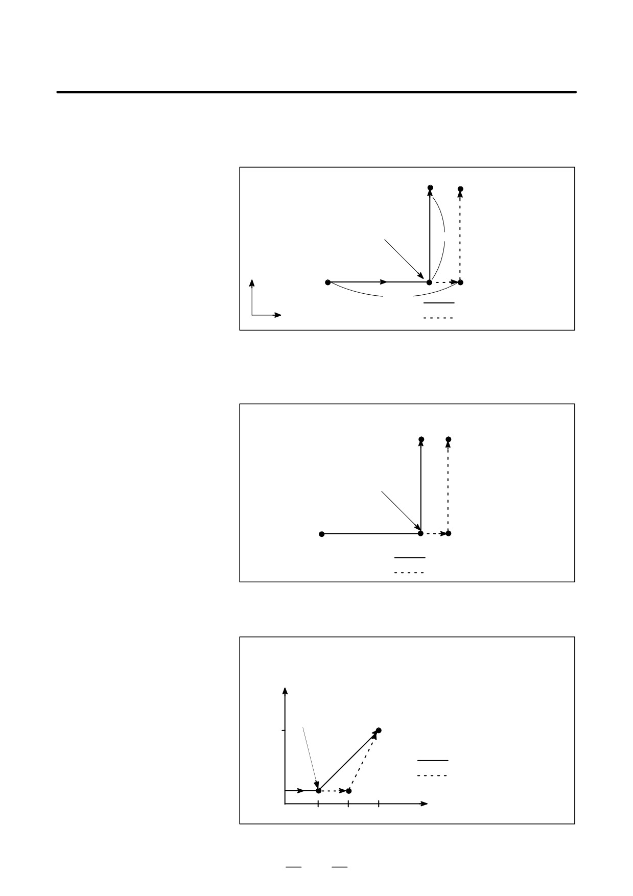
D The next block to G31 is
an incremental
command
G31
G91X100.0 F100;
Y50.0;
Skip signal is input here
50.0
Y
100.0
Actual motion
X
Motion without skip signal
Fig. 4.8 (a) The next block is an incremental command
D The next block to G31 is
an absolute command
for 1 axis
G31
G90X200.00 F100;
Y100.0
Y100.0;
Skip signal is input here
X200.0
Actual motion
Motion without skip signal
Fig. 4.8 (b) The next block is an absolute command for 1 axis
D The next block to G31 is
an absolute command
for 2 axes
G31
G90X200.0 F100;
X300.0 Y100.0;
Y
Skip signal is input here
100
(300,100)
Actual motion
Motion without skip signal
X
100
200
300
Fig. 4.8 (c) The next block is an absolute command for 2 axes
54
B-64124EN/01
PROGRAMMING
4. INTERPOLATION FUNCTIONS
4.9
The skip function operates based on a high-speed skip signal (connected
directly to the NC; not via the PMC) instead of an ordinary skip signal.
HIGH SPEED SKIP
In this case, up to eight signals can be input.
SIGNAL (G31)
Delay and error of skip signal input is 0 - 2 msec at the NC side (not
considering those at the PMC side).
This high-speed skip signal input function keeps this value to 0.1 msec
or less, thus allowing high precision measurement.
For details, refer to the appropriate manual supplied from the machine
tool builder.
Format
G31 IP_ ;
G31: One-shot G code (If is effective only in the block in which it is
specified)
55
4. INTERPOLATION FUNCTIONS
PROGRAMMING
B-64124EN/01
4.10
In a block specifying P1 to P4 after G31, the multistage skip function
stores coordinates in a custom macro variable when a skip signal (4-point
MULTISTAGE SKIP
or 8-point ; 8-point when a high-speed skip signal is used) is turned on.
(G31)
Parameters No. 6202 to No. 6205 can be used to select a 4-point or
8-point (when a high-speed skip signal is used) skip signal. One skip
signal can be set to match multiple Pn or Qn (n=1,2,3,4) as well as to
match a Pn or Qn on a one-to-one basis. Parameters DS1 to DS8 (No.
6206 #0A#7) can be used for dwell.
A skip signal from equipment such as a fixed-dimension size measuring
instrument can be used to skip programs being executed.
In plunge grinding, for example, a series of operations from rough
machining to spark-out can be performed automatically by applying a
skip signal each time rough machining, semi-fine machining,
fine-machining, or spark-out operation is completed.
Format
Move command
G31 IIP__ F __ P __ ;
IP_ : End point
F_ : Feedrate
P_ : P1-P4
Dwell
G04 X (U, P)__ (Q__)
;
X(U, P)_ : Dwell time
Q_ : Q1 - Q4
Explanations
Multistage skip is caused by specifying P1, P2, P3, or P4 in a G31 block.
For an explanation of selecting (P1, P2, P3, or P4), refer to the manual
supplied by the machine tool builder.
Specifying Q1, Q2, Q3, or Q4 in G04 (dwell command) enables dwell
skip in a similar way to specifying G31. A skip may occur even if Q is
not specified. For an explanation of selecting (Q1, Q2, Q3, or Q4), refer
to the manual supplied by the machine tool builder.
D Correspondence to skip
Parameter Nos. 6202 to 6205 can be used to specify whether the 4-point
signals
or 8-point skip signal is used (when a high-speed skip signal is used).
Specification is not limited to one-to-one correspondence. It is possible
to specify that one skip signal correspond to two or more Pn’s or Qn’s
(n=1, 2, 3, 4). Also, bits 0 (DS1) to 7 (DS8) of parameter No. 6206 can
be used to specify dwell.
CAUTION
Dwell is not skipped when Qn is not specified and
parameters DS1-DS8 (No. 6206#0-#7) are not set.
56
B-64124EN/01
PROGRAMMING
4. INTERPOLATION FUNCTIONS
4.11
With the motor torque limited (for example, by a torque limit command,
issued through the PMC window), a move command following G31 P99
TORQUE LIMIT SKIP
(or G31 P98) can cause the same type of cutting feed as with G01 (linear
(G31 P99)
interpolation).
With the issue of a signal indicating a torque limit has been reached
(because of pressure being applied or for some other reason), a skip
occurs.
For details of how to use this function, refer to the manuals supplied by
the machine tool builder.
Format
G31 P99 IP_ F_ ;
G31 P98 IP_ F_ ;
G31: One-shot G code (G code effective only in the block in which it
is issued)
Explanations
D G31 P99
If the motor torque limit is reached, or a SKIP signal is received during
execution of G31 P99, the current move command is aborted, and the next
block is executed.
D G31 P98
If the motor torque limit is reached during execution of G31 P98, the
current move command is aborted, and the next block is executed. The
SKIP signal <X0004#7> does not affect G31 P98.
Entering a SKIP signal during the execution of G31 P98 does not cause
a skip.
D Torque limit command
If a torque limit is not specified before the execution of G31 P99/98, the
move command continues; no skip occurs even if a torque limit is
reached.
D Custom macro system
When G31 P99/98 is specified, the custom macro variables hold the
variable
coordinates at the end of a skip.
(See Section 4.8.)
If a SKIP signal causes a skip with G31 P99, the custom macro system
variables hold the coordinates based on the machine coordinate system
when it stops, rather than those when the SKIP signal is entered.
Limitations
D Axis command
Only one axis can be controlled in each block with G31 P98/99.
If two or more axes are specified to be controlled in such blocks, or no axis
command is issued, P/S alarm No. 015 is generated.
D Degree of servo error
When a signal indicating that a torque limit has been reached is input
during execution of G31 P99/98, and the degree of servo error exceeds
32767, P/S alarm No. 244 is generated.
D High-speed skip
With G31 P99, a SKIP signal can cause a skip, but not a high-speed skip.
57
4. INTERPOLATION FUNCTIONS
PROGRAMMING
B-64124EN/01
D Simplified
G31 P99/98 cannot be used for axes subject to simplified synchronization
synchronization and
or the X-axis or Z-axis when under slanted axis control.
slanted axis control
D Speed control
Bit 7 (SKF) of parameter No. 6200 must be set to disable dry run,
override, and auto acceleration or deceleration for G31 skip commands.
Do not use G31 P99/98 in consecutive blocks.
D Consecutive commands
WARNING
Always specify a torque limit before a G31 P99/98
command.
Otherwise, G31 P99/98 allows move
commands to be executed without causing a skip.
Examples
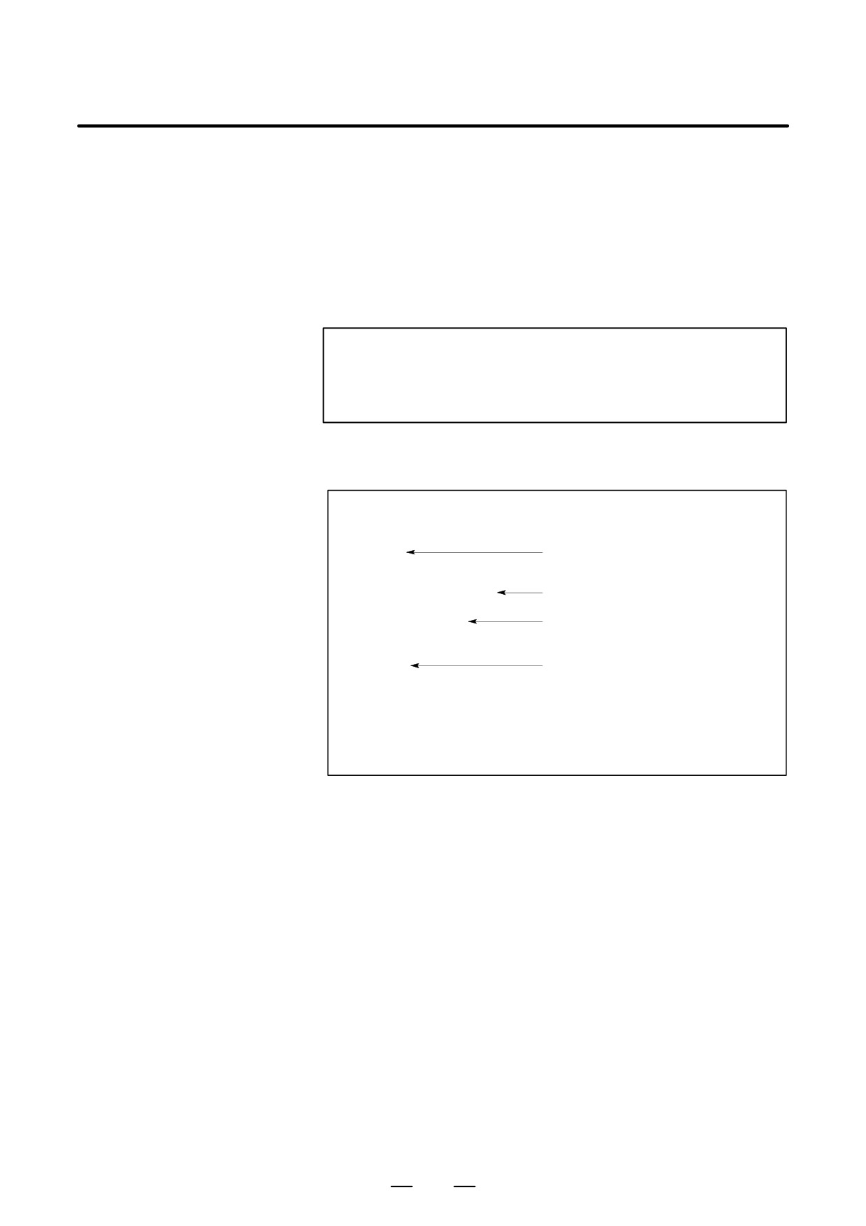
O0001 ;
:
:
The PMC specifies the torque limit
Mjj ;
through the window.
:
:
G31 P99 X200. F100 ;
Torque limit skip command
:
Move command for which a torque
G01 X100. F500 ;
limit is applied
:
:
MDD ;
Torque limit canceled by the PMC
:
:
M30 ;
:
%
58
B-64124EN/01
PROGRAMMING
5. FEED FUNCTIONS
FEED FUNCTIONS
5
59
5. FEED FUNCTIONS
PROGRAMMING
B-64124EN/01
The feed functions control the feedrate of the tool. The following two feed
5.1
functions are available:
GENERAL
D Feed functions
1. Rapid traverse
When the positioning command (G00) is specified, the tool moves at
a rapid traverse feedrate set in the CNC (parameter No. 1420).
2. Cutting feed
The tool moves at a programmed cutting feedrate.
D Override
Override can be applied to a rapid traverse rate or cutting feedrate using
the switch on the machine operator’s panel.
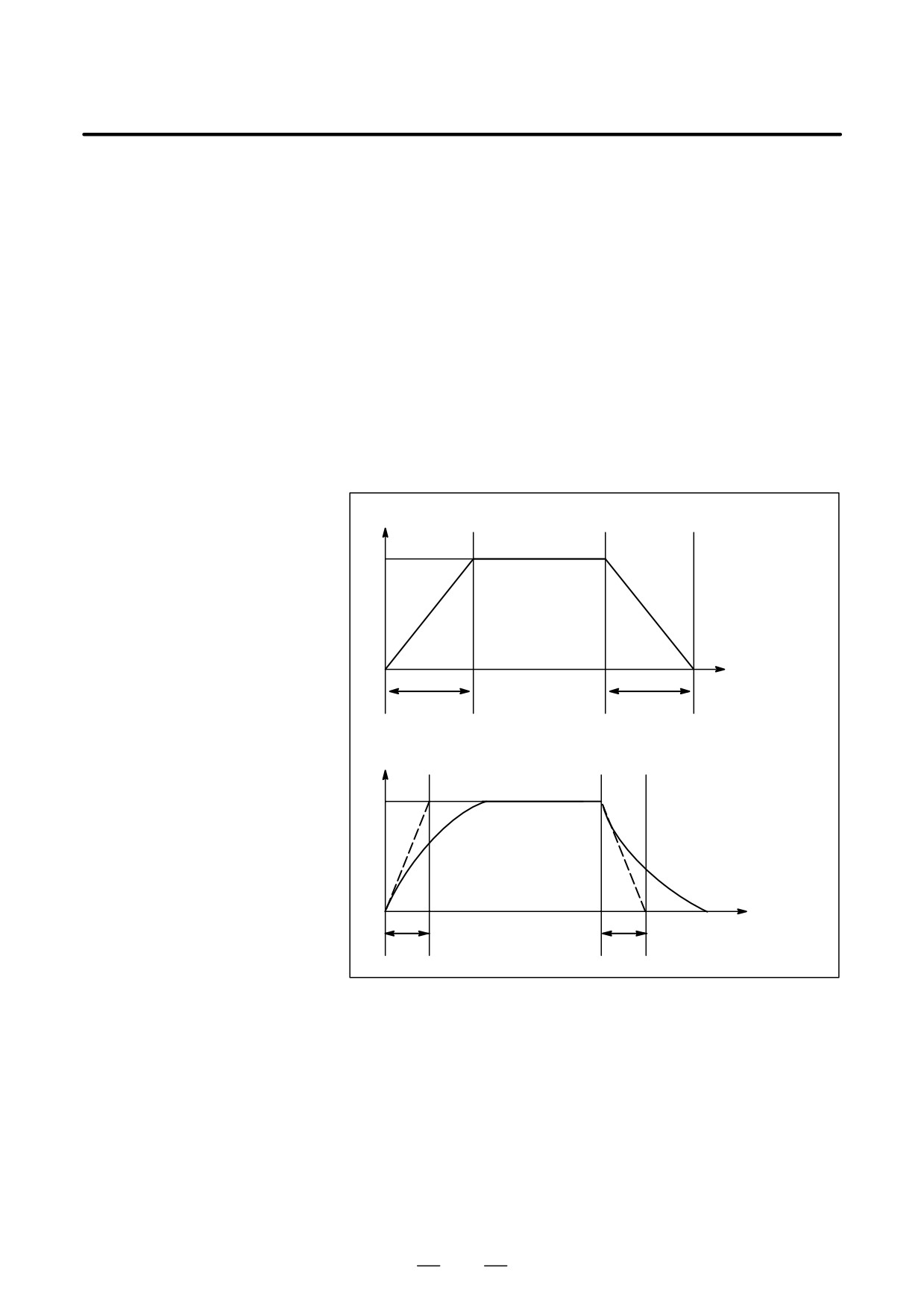
D Automatic acceleration/
To prevent a mechanical shock, acceleration/deceleration is automatically
deceleration
applied when the tool starts and ends its movement (Fig. 5.1 (a)).
Rapid traverse rate
FR : Rapid traverse
FR
rate
TR
: Acceleration/
deceleration time
constant for rap-
id traverse rate
0
Time
TR
TR
Feed rate
FC
: Feedrate
FC
TC : Acceleration/
deceleration time
constant for a cut-
ting feedrate
0
Time
TC
TC
Fig. 5.1 (a) Automatic acceleration/deceleration (example)
60
B-64124EN/01
PROGRAMMING
5. FEED FUNCTIONS
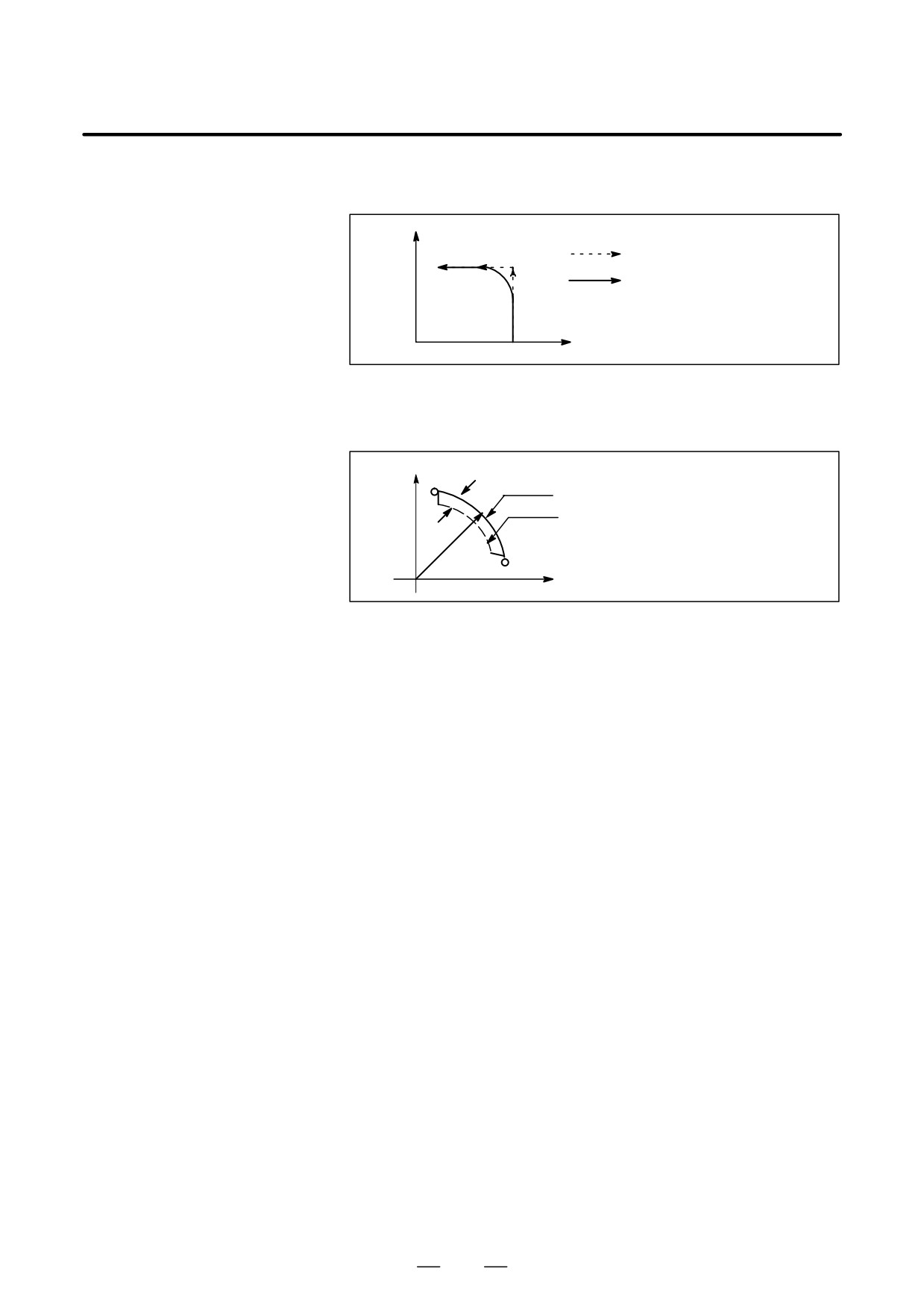
D Tool path in a cutting
If the direction of movement changes between specified blocks during
feed
cutting feed, a rounded-corner path may result (Fig. 5.1 (b)).
Y
Programmed path
Actual tool path
0
X
Fig. 5.1 (b) Example of tool path between two blocks
In circular interpolation, a radial error occurs (Fig. 5.1 (c)).
Y
∆r:Error
Programmed path
Actual tool path
r
0
X
Fig. 5.1 (c) Example of radial error in circular interpolation
The rounded-corner path shown in Fig. 5.1 (b) and the error shown in
Fig. 5.1 (c) depend on the feedrate. So, the feedrate needs to be controlled
for the tool to move as programmed.
61
5. FEED FUNCTIONS
PROGRAMMING
B-64124EN/01
5.2
RAPID TRAVERSE
Format
G00 IP_ ;
G00 : G code (group 01) for positioning (rapid traverse)
IP_ ; Dimension word for the end point
Explanations
The positioning command (G00) positions the tool by rapid traverse. In
rapid traverse, the next block is executed after the specified feedrate
becomes 0 and the servo motor reaches a certain range set by the machine
tool builder (in-position check).
A rapid traverse rate is set for each axis by parameter No. 1420, so no rapid
traverse feedrate need be programmed.
The following overrides can be applied to a rapid traverse rate with the
switch on the machine operator’s panel:F0, 25, 50, 100%
F0: Allows a fixed feedrate to be set for each axis by parameter No. 1421.
For detailed information, refer to the appropriate manual of the machine
tool builder.
62
B-64124EN/01
PROGRAMMING
5. FEED FUNCTIONS
Feedrate of linear interpolation (G01), circular interpolation (G02, G03),
5.3
etc. are commanded with numbers after the F code.
CUTTING FEED
In cutting feed, the next block is executed so that the feedrate change from
the previous block is minimized.
Four modes of specification are available:
1.
Feed per minute (G94)
After F, specify the amount of feed of the tool per minute.
2.
Feed per revolution (G95)
After F, specify the amount of feed of the tool per spindle revolution.
3.
Inverse time feed (G93)
Specify the inverse time (FRN) after F.
4.
F1-digit feed
Specify a desired one-digit number after F. Then, the feedrate set with
the CNC for that number is set.
Format
Feed per minute
G94 ; G code (group 05) for feed per minute
F_ ; Feedrate command (mm/min or inch/min)
Feed per revolution
G95 ; G code (group 05) for feed per revolution
F_ ; Feedrate command (mm/rev or inch/rev)
Inverse time feed (G93)
G93 ; Inverse time feed command
G code (05 group)
F_ ; Feedrate command (1/min)
F1-digit feed
Fn ;
n : Number from 1 to 9
Explanations
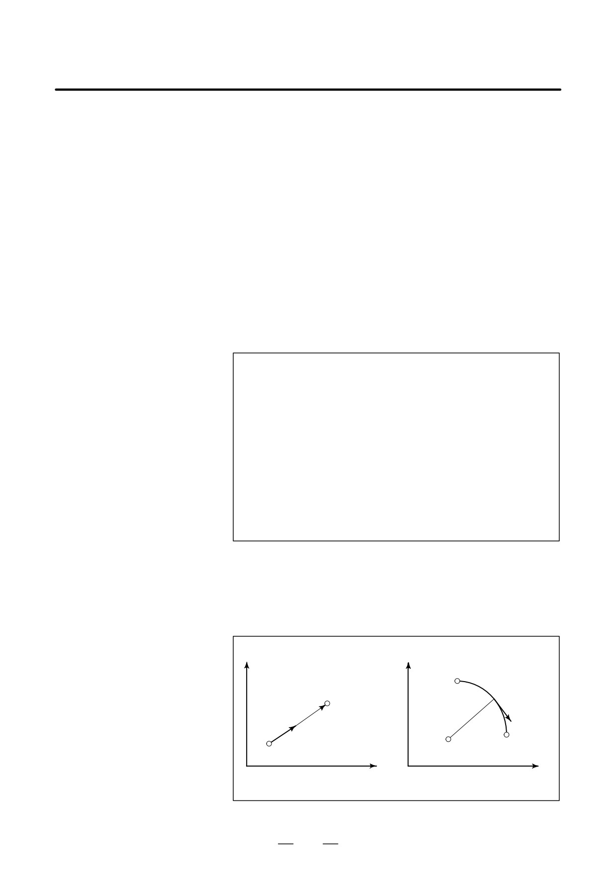
D Tangential speed
Cutting feed is controlled so that the tangential feedrate is always set at
constant control
a specified feedrate.
Y
Y
Starting
End point
point
F
F
Start
point
Center
End point
X
X
Linear interpolation
Circular interpolation
Fig. 5.3 (a) Tangential feedrate (F)
63
5. FEED FUNCTIONS
PROGRAMMING
B-64124EN/01
D Feed per minute (G94)
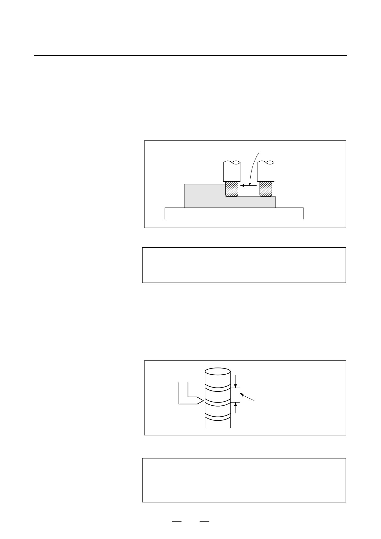
After specifying G94 (in the feed per minute mode), the amount of feed
of the tool per minute is to be directly specified by setting a number after
F. G94 is a modal code. Once a G94 is specified, it is valid until G95 (feed
per revolution) is specified. At power-on, the feed per minute mode is
set.
An override from 0% to 254% (in 1% steps) can be applied to feed per
minute with the switch on the machine operator’s panel. For detailed
information, see the appropriate manual of the machine tool builder.
Feed amount per minute
(mm/min or inch/min)
Tool
Workpiece
Table
Fig. 5.3 (b) Feed per minute
WARNING
No override can be used for some commands such as for
threading.
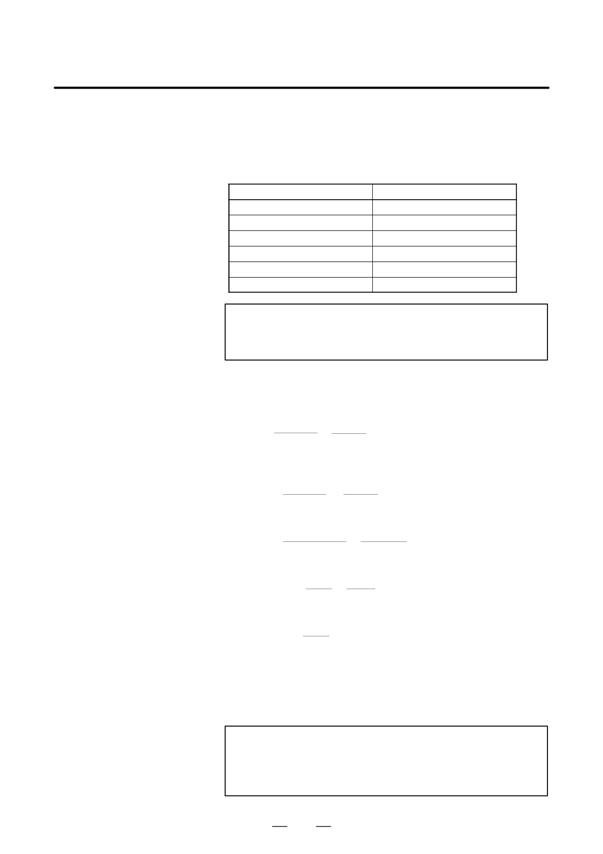
D Feed per revolution
After specifying G95 (in the feed per revolution mode), the amount of
(G95)
feed of the tool per spindle revolution is to be directly specified by setting
a number after F. G95 is a modal code. Once a G95 is specified, it is valid
until G94 (feed per minute) is specified.
An override from 0% to 254% (in 1% steps) can be applied to feed per
revolution with the switch on the machine operator’s panel. For detailed
information, see the appropriate manual of the machine tool builder.
F
Feed amount per spindle revolution
(mm/rev or inch/rev)
Fig. 5.3 (c) Feed per revolution
CAUTION
When the speed of the spindle is low, feedrate fluctuation
may occur. The slower the spindle rotates, the more
frequently feedrate fluctuation occurs.
64
B-64124EN/01
PROGRAMMING
5. FEED FUNCTIONS
D Inverse time feed (G93)
When G93 is specified, the inverse time specification mode (G93 mode)
is set. Specify the inverse time (FRN) with an F code.
A value from 0.001 to 9999.999 can be specified as FRN, regardless of
whether the input mode is inches or metric, or the increment system is
IS-B or IS-C.
F code specification value
FRN
F1
0.001
F1 *1
1.000
F1.0
1.000
F9999999
9999.999
F9999 *1
9999.000
F9999.999
9999.999
NOTE
*1
Value specified in fixed-point format with bit 0 (DPI) of parameter
No. 3401 set to 1
Explanations
For linear interpolation (G01)
1
feedrate
Feedrate:mm/min
(for metric input)
FRN=
=
time (min)
distance
inch/min(for inch input)
Distance:mm
(for metric input)
inch(for inch input)
- To end a block in 1 (min)
1
1
FRN =
=
= 1
Specify F1.0.
time (min)
1 (min)
- To end a block in 10 (sec)
1
1
FRN =
=
= 6
Specify F6.0.
time (sec) / 60
10/60 (sec)
- To find the movement time required when F0.5 is specified
1
1
Time
(min) =
=
= 2
2 (min) is required.
FRN
0.5
- To find the movement time required when F10.0 is specified
1
60
60
Time (sec) =
=
= 6
6 (sec) is required.
FRN
10
For circular interpolation (G01)
1
feedrate Feedrate: mm/min (for metric input)
FRN=
=
time (min) arc radius inch/min(for inch input)
Arc radius: mm (for metric input)
inch(for inch input)
NOTE
In the case of circular interpolation, the feedrate
is
calculated notfrom the actual amount of movement in the
block but from the arcradius.
65

5. FEED FUNCTIONS
PROGRAMMING
B-64124EN/01
G93 is a modal G code and belongs to group 05 (includes G95 (feed per
revolution) and G94 (feed per minute)).
When an F value is specified in G93 mode and the feedrate exceeds the
maximum cutting feedrate, the feedrate is clamped to the maximum
cutting feedrate.
In the case of circular interpolation, the feedrate is calculated not from the
actual amount of movement in the block but from the arc radius. This
means that actual machining time is longer when the arc radius is longer
than the arc distance and shorter when the arc radius is shorter than the arc
distance. Inverse time feed can also be used for cutting feed in a canned
cycle.Notes
NOTE
1
In the G93 mode, an F code is not handled as a modal code and
therefore needs to be specified in each block. If an F code is not
specified, P/S alarm (No. 11 (indicating that cutting feedrate
specification is missing)) is issued.
2
When F0 is specified in G93 mode, P/S alarm (No. 11 (indicating
that cutting feedrate specification is missing)) is issued.
3
Inverse time feed cannot be used when PMC axis control is in
effect.
4
If the calculated cutting feedrate is smaller than the allowable
range, P/S alarm
(No.
11
(indicating that cutting feedrate
specification is missing)) is issued.
66
B-64124EN/01
PROGRAMMING
5. FEED FUNCTIONS
D One-digit F code feed
When a one-digit number from 1 to 9 is specified after F, the feedrate
set for that number in a parameter (Nos. 1451 to 1459) is used. When
F0 is specified, the rapid traverse rate is applied.
The feedrate corresponding to the number currently selected can be
increased or decreased by turning on the switch for changing F1-digit
feedrate on the machine operator’s panel, then by rotating the manual
pulse generator.
The increment/decrement, ∆F, in feedrate per scale of the manual pulse
generator is as follows:
∆F+Fmax
100X
Fmax : feedrate upper limit for F1-F4 set by parameter (No.1460), or
feedrate upper limit for F5-F9 set by parameter (No.1461)
X :any value of 1-127 set by parameter (No.1450)
The feedrate set or altered is kept even while the power is off. The current
feed rate is displayed on the CRT screen.
D Cutting feedrate clamp
A common upper limit can be set on the cutting feedrate along each axis
with parameter No. 1422. If an actual cutting feedrate (with an override
applied) exceeds a specified upper limit, it is clamped to the upper limit.
Parameter No. 1430 can be used to specify the maximum cutting feedrate
for each axis only for linear interpolation and circular interpolation.
When the cutting feedrate along an axis exceeds the maximum feedrate
for the axis as a result of interpolation, the cutting feedrate is clamped to
the maximum feedrate.
NOTE
An upper limit is set in mm/min or inch/min. CNC calculation
may involve a feedrate error of ±2% with respect to a
specified value. However, this is not true for
acceleration/deceleration. To be more specific, this error is
calculated with respect to a measurement on the time the
tool takes to move 500 mm or more during the steady state:
Reference
See Appendix C for range of feedrate command value.
67
5. FEED FUNCTIONS
PROGRAMMING
B-64124EN/01
Cutting feedrate can be controlled, as indicated in Table 5.4.
5.4
CUTTING FEEDRATE
CONTROL
Table 5.4 Cutting Feedrate Control
Function name
G code
Validity of G code
Description
Exact stop
This function is valid for specified
The tool is decelerated at the end point
G09
blocks only.
of a block, then an in-position check is
made. Then the next block is executed.
Exact stop mode
Once specified, this function is
The tool is decelerated at the end point
G61
valid until G62, G63, or G64 is
of a block, then an in-position check is
specified.
made. Then the next block is executed.
Cutting mode
Once specified, this function is
The tool is not decelerated at the end
G64
valid until G61, G62, or G63 is
point of a block, but the next block is
specified.
executed.
Tapping mode
Once specified, this function is
The tool is not decelerated at the end
valid until G61, G62, or G64 is
point of a block, but the next block is
G63
specified.
executed.
When G63 is specified, feedrate override
and feed hold are invalid.
Auto- Automatic override for
Once specified, this function is
When the tool moves along an inner
matic
inner corners
valid until G61, G63, or G64 is
corner during cutter compensation, over-
specified.
ride is applied to the cutting feedrate to
G62
suppress the amount of cutting per unit
of time so that a good surface finish can
be produced.
Internal circular cutting
This function is valid in the cutter
The internal circular cutting feedrate is
feedrate change
_
compensation mode, regardless of
changed.
the G code.
NOTE
1
The purpose of in-position check is to check that the servo
motor has reached within a specified range (specified with
a parameter by the machine tool builder).
In-position check is not performed when bit 5 (NCI) of
parameter No. 1601 is set to 1.
2
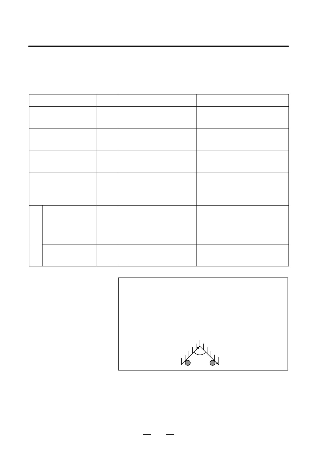
Inner corner angle θ: 2°< θ x α x 178°
(α is a set value)
Workpiece
θ
Tool
68
B-64124EN/01
PROGRAMMING
5. FEED FUNCTIONS
Format
Exact stop
G09 IP_ ;
Exact stop mode
G61 ;
Cutting mode
G64 ;
Tapping mode
G63 ;
Automatic corner override G62 ;
5.4.1
Exact Stop (G09, G61)
Cutting Mode (G64)
Tapping Mode (G63)
Explanations
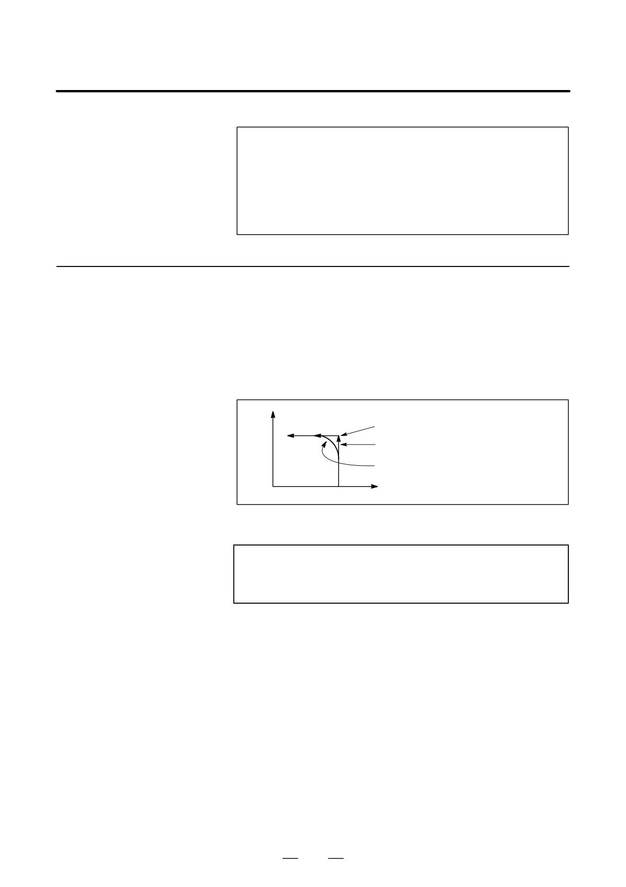
The inter-block paths followed by the tool in the exact stop mode, cutting
mode, and tapping mode are different (Fig. 5.4.1).
Y
Position check
(2)
Tool path in the exact stop mode
(1)
Tool path in the cutting mode or
tapping mode
0
X
Fig. 5.4.1 Example of tool paths from block (1) to block (2)
CAUTION
The cutting mode (G64 mode) is set at power-on or system
clear.
69
5. FEED FUNCTIONS
PROGRAMMING
B-64124EN/01
5.4.2
When cutter compensation is performed, the movement of the tool is
automatically decelerated at an inner corner and internal circular area.
Automatic Corner
This reduces the load on the cutter and produces a smoothly machined
Override
surface.
5.4.2.1
Automatic Override for
Inner Corners (G62)
Explanations
D Override condition
When G62 is specified, and the tool path with cutter compensation
applied forms an inner corner, the feedrate is automatically overridden
at both ends of the corner.
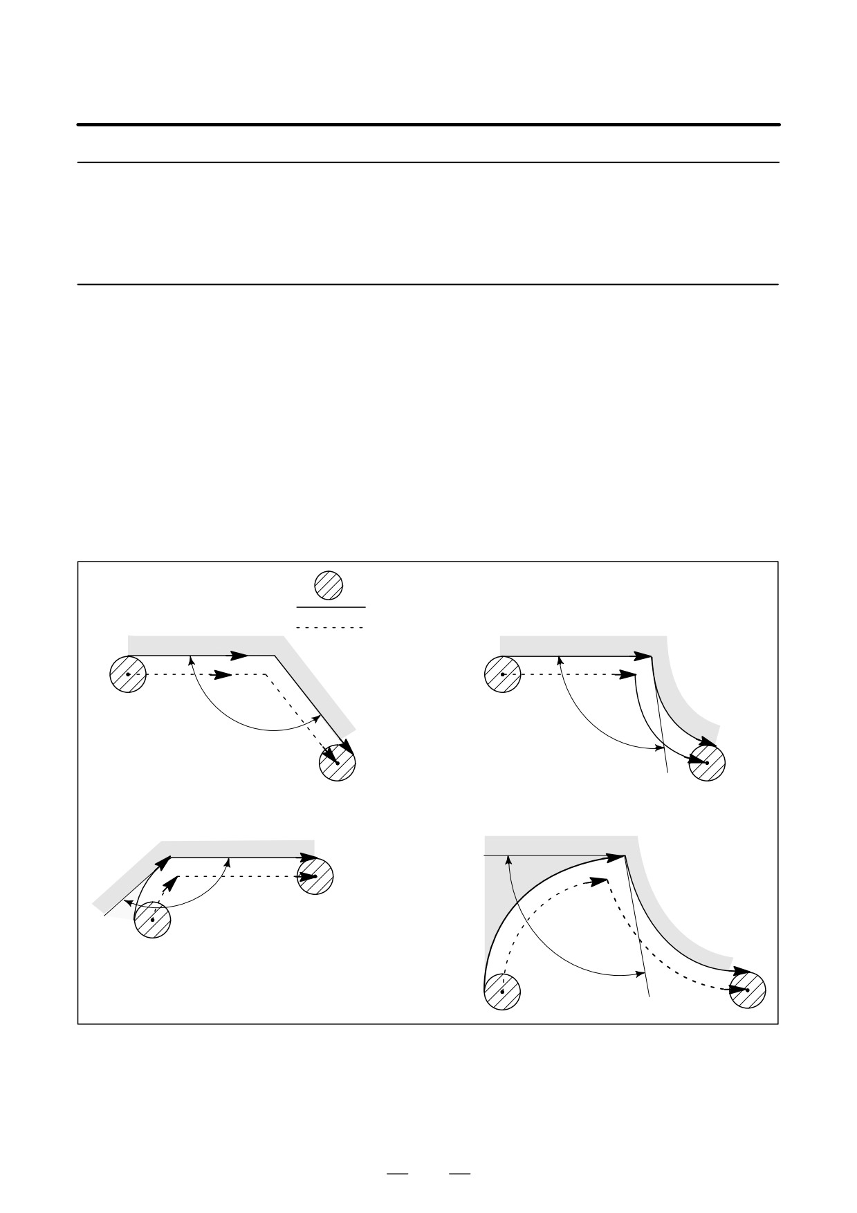
There are four types of inner corners (Fig. 5.4.2.1 (a)).
2,xθxθpx178, in Fig. 5.4.2.1 (a)
θp is a value set with parameter No. 1711. When θ is approximately
equal to θp, the inner corner is determined with an error of 0.001,or
less.
1. Straight line-straight line
:Tool
2. Straight line-arc
:Programmed path
:Cutter center path
θ
θ
3. Arc-straight line
4. Arc-arc
θ
θ
Fig. 5.4.2.1 (a) Inner corner
70
B-64124EN/01
PROGRAMMING
5. FEED FUNCTIONS
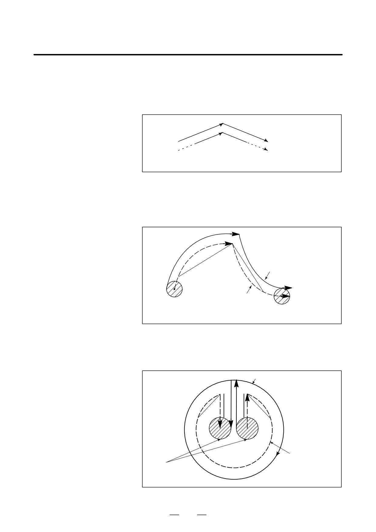
Override range
When a corner is determined to be an inner corner, the feedrate is
overridden before and after the inner corner. The distances Ls and Le,
where the feedrate is overridden, are distances from points on the cutter
center path to the corner (Fig. 5.4.2.1 (b), Fig. 5.4.2.1 (c), Fig. 5.4.2.1 (d)).
Ls and Le are set with parameter Nos. 1713 and 1714.
Programmed path
Le
Ls
b
a
Cutter center path
The feedrate is overridden from point a to point b.
FIg. 5.4.2.1 (b) Override Range (Straight Line to Straight Line)
When a programmed path consists of two arcs, the feedrate is overridden
if the start and end points are in the same quadrant or in adjacent quadrants
(Fig. 5.4.2.1 (c)).
Le
Programmed path
Ls
a
b
Cutter center path
The feedrate is overridden from point a to b.
Fig. 5.4.2.1 (c) Override Range (Arc to Arc)
Regarding program (2) of an arc, the feedrate is overridden from point a
to point b and from point c to point d (Fig. 5.4.2.1 (d)).
Programmed path
d
a
Le
Ls
Le
Ls
c
b
(2)
Cutter center path
Tool
Fig. 5.4.2.1 (d) Override Range (Straight Line to Arc, Arc to Straight Line)
71
5. FEED FUNCTIONS
PROGRAMMING
B-64124EN/01
Override value
An override value is set with parameter No. 1712. An override value is
valid even for dry run and F1-digit specification.
In the feed per minute mode, the actual feedrate is as follows:
F × (automatic override for inner corners) × (feedrate override)
Limitations
D Acceleration/deceleratio
Override for inner corners is disabled during acceleration/deceleration
n before interpolation
before interpolation.
D Start-up/G41, G42
Override for inner corners is disabled if the corner is preceded by a
start-up block or followed by a block including G41 or G42.
D Offset
Override for inner corners is not performed if the offset is zero.
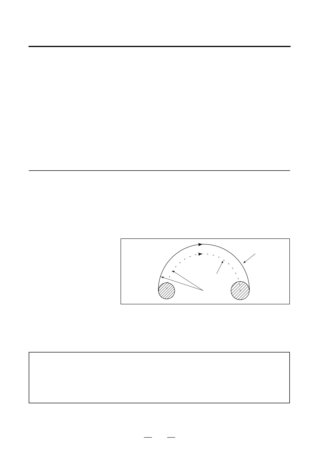
5.4.2.2
For internally offset circular cutting, the feedrate on a programmed path
is set to a specified feedrate (F) by specifying the circular cutting feedrate
Internal Circular Cutting
with respect to F, as indicated below (Fig. 5.4.2.2). This function is valid
Feedrate Change
in the cutter compensation mode, regardless of the G62 code.
Rc
F
Rp
Rc : Cutter center path radius
Rp : Programmed radius
It is also valid for the dry run and the one-digit F command.
Programmed path
Rc Cutter center
path
Rp
Fig. 5.4.2.2 Internal circular cutting feedrate change
If Rc is much smaller than Rp, Rc/Rp80; the tool stops. A minimum
deceleration ratio (MDR) is to be specified with parameter No. 1710.
When Rc/RpxMDR, the feedrate of the tool is (F×MDR).
NOTE
When internal circular cutting must be performed together with override for inner corners, the
feedrate of the tool is as follows:
Rc
F
(override for the inner corners)×(feedrate override)
Rp
72