FANUC Series 0i-MC. OPERATOR’S MANUAL - page 1
SAFETY PRECAUTIONS
This section describes the safety precautions related to the use of CNC units. It is essential that these precautions
be observed by users to ensure the safe operation of machines equipped with a CNC unit (all descriptions in this
section assume this configuration). Note that some precautions are related only to specific functions, and thus
may not be applicable to certain CNC units.
Users must also observe the safety precautions related to the machine, as described in the relevant manual supplied
by the machine tool builder. Before attempting to operate the machine or create a program to control the operation
of the machine, the operator must become fully familiar with the contents of this manual and relevant manual
supplied by the machine tool builder.
Contents
1. DEFINITION OF WARNING, CAUTION, AND NOTE .
s-2
2. GENERAL WARNINGS AND CAUTIONS .
s-3
3. WARNINGS AND CAUTIONS RELATED TO PROGRAMMING .
s-5
4. WARNINGS AND CAUTIONS RELATED TO HANDLING .
s-7
5. WARNINGS RELATED TO DAILY MAINTENANCE .
s-9
s-1
SAFETY PRECAUTIONS
B-64124EN/01
DEFINITION OF WARNING, CAUTION, AND NOTE
1
This manual includes safety precautions for protecting the user and preventing damage to the
machine. Precautions are classified into Warning and Caution according to their bearing on safety.
Also, supplementary information is described as a Note. Read the Warning, Caution, and Note
thoroughly before attempting to use the machine.
WARNING
Applied when there is a danger of the user being injured or when there is a danger of both the user
being injured and the equipment being damaged if the approved procedure is not observed.
CAUTION
Applied when there is a danger of the equipment being damaged, if the approved procedure is not
observed.
NOTE
The Note is used to indicate supplementary information other than Warning and Caution.
` Read this manual carefully, and store it in a safe place.
s-2
B-64124EN/01
SAFETY PRECAUTIONS
GENERAL WARNINGS AND CAUTIONS
2
WARNING
1.
Never attempt to machine a workpiece without first checking the operation of the machine.
Before starting a production run, ensure that the machine is operating correctly by performing
a trial run using, for example, the single block, feedrate override, or machine lock function or
by operating the machine with neither a tool nor workpiece mounted. Failure to confirm the
correct operation of the machine may result in the machine behaving unexpectedly, possibly
causing damage to the workpiece and/or machine itself, or injury to the user.
2.
Before operating the machine, thoroughly check the entered data.
Operating the machine with incorrectly specified data may result in the machine behaving
unexpectedly, possibly causing damage to the workpiece and/or machine itself, or injury to the
user.
3.
Ensure that the specified feedrate is appropriate for the intended operation. Generally, for each
machine, there is a maximum allowable feedrate. The appropriate feedrate varies with the
intended operation. Refer to the manual provided with the machine to determine the maximum
allowable feedrate. If a machine is run at other than the correct speed, it may behave
unexpectedly, possibly causing damage to the workpiece and/or machine itself, or injury to the
user.
4.
When using a tool compensation function, thoroughly check the direction and amount of
compensation.
Operating the machine with incorrectly specified data may result in the machine behaving
unexpectedly, possibly causing damage to the workpiece and/or machine itself, or injury to the
user.
5.
The parameters for the CNC and PMC are factory-set. Usually, there is not need to change them.
When, however, there is not alternative other than to change a parameter, ensure that you fully
understand the function of the parameter before making any change.
Failure to set a parameter correctly may result in the machine behaving unexpectedly, possibly
causing damage to the workpiece and/or machine itself, or injury to the user.
6.
Immediately after switching on the power, do not touch any of the keys on the MDI panel until
the position display or alarm screen appears on the CNC unit.
Some of the keys on the MDI panel are dedicated to maintenance or other special operations.
Pressing any of these keys may place the CNC unit in other than its normal state. Starting the
machine in this state may cause it to behave unexpectedly.
7.
The operator’s manual and programming manual supplied with a CNC unit provide an overall
description of the machine’s functions, including any optional functions. Note that the optional
functions will vary from one machine model to another. Therefore, some functions described
in the manuals may not actually be available for a particular model. Check the specification of
the machine if in doubt.
s-3
SAFETY PRECAUTIONS
B-64124EN/01
WARNING
8. Some functions may have been implemented at the request of the machine-tool builder. When
using such functions, refer to the manual supplied by the machine-tool builder for details of their
use and any related cautions.
NOTE
Programs, parameters, and macro variables are stored in nonvolatile memory in the CNC unit.
Usually, they are retained even if the power is turned off. Such data may be deleted inadvertently,
however, or it may prove necessary to delete all data from nonvolatile memory as part of error
recovery.
To guard against the occurrence of the above, and assure quick restoration of deleted data, backup
all vital data, and keep the backup copy in a safe place.
s-4
B-64124EN/01
SAFETY PRECAUTIONS
WARNINGS AND CAUTIONS RELATED TO
PROGRAMMING
3
This section covers the major safety precautions related to programming. Before attempting to
perform programming, read the supplied operator’s manual and programming manual carefully
such that you are fully familiar with their contents.
WARNING
1.
Coordinate system setting
If a coordinate system is established incorrectly, the machine may behave unexpectedly as a
result of the program issuing an otherwise valid move command.
Such an unexpected operation may damage the tool, the machine itself, the workpiece, or cause
injury to the user.
2.
Positioning by nonlinear interpolation
When performing positioning by nonlinear interpolation (positioning by nonlinear movement
between the start and end points), the tool path must be carefully confirmed before performing
programming.
Positioning involves rapid traverse. If the tool collides with the workpiece, it may damage the
tool, the machine itself, the workpiece, or cause injury to the user.
3.
Function involving a rotation axis
When programming polar coordinate interpolation or normal-direction (perpendicular) control,
pay careful attention to the speed of the rotation axis. Incorrect programming may result in the
rotation axis speed becoming excessively high, such that centrifugal force causes the chuck to
lose its grip on the workpiece if the latter is not mounted securely.
Such mishap is likely to damage the tool, the machine itself, the workpiece, or cause injury to
the user.
4.
Inch/metric conversion
Switching between inch and metric inputs does not convert the measurement units of data such
as the workpiece origin offset, parameter, and current position. Before starting the machine,
therefore, determine which measurement units are being used. Attempting to perform an
operation with invalid data specified may damage the tool, the machine itself, the workpiece, or
cause injury to the user.
5.
Constant surface speed control
When an axis subject to constant surface speed control approaches the origin of the workpiece
coordinate system, the spindle speed may become excessively high. Therefore, it is necessary
to specify a maximum allowable speed. Specifying the maximum allowable speed incorrectly
may damage the tool, the machine itself, the workpiece, or cause injury to the user.
s-5
SAFETY PRECAUTIONS
B-64124EN/01
WARNING
6. Stroke check
After switching on the power, perform a manual reference position return as required. Stroke
check is not possible before manual reference position return is performed. Note that when stroke
check is disabled, an alarm is not issued even if a stroke limit is exceeded, possibly damaging
the tool, the machine itself, the workpiece, or causing injury to the user.
7. Tool post interference check
A tool post interference check is performed based on the tool data specified during automatic
operation. If the tool specification does not match the tool actually being used, the interference
check cannot be made correctly, possibly damaging the tool or the machine itself, or causing
injury to the user.
After switching on the power, or after selecting a tool post manually, always start automatic
operation and specify the tool number of the tool to be used.
8. Absolute/incremental mode
If a program created with absolute values is run in incremental mode, or vice versa, the machine
may behave unexpectedly.
9. Plane selection
If an incorrect plane is specified for circular interpolation, helical interpolation, or a canned cycle,
the machine may behave unexpectedly. Refer to the descriptions of the respective functions for
details.
10. Torque limit skip
Before attempting a torque limit skip, apply the torque limit. If a torque limit skip is specified
without the torque limit actually being applied, a move command will be executed without
performing a skip.
11. Programmable mirror image
Note that programmed operations vary considerably when a programmable mirror image is
enabled.
12. Compensation function
If a command based on the machine coordinate system or a reference position return command
is issued in compensation function mode, compensation is temporarily canceled, resulting in the
unexpected behavior of the machine.
Before issuing any of the above commands, therefore, always cancel compensation function
mode.
s-6
B-64124EN/01
SAFETY PRECAUTIONS
WARNINGS AND CAUTIONS RELATED TO HANDLING
4
This section presents safety precautions related to the handling of machine tools. Before attempting
to operate your machine, read the supplied operator’s manual and programming manual carefully,
such that you are fully familiar with their contents.
WARNING
1.
Manual operation
When operating the machine manually, determine the current position of the tool and workpiece,
and ensure that the movement axis, direction, and feedrate have been specified correctly.
Incorrect operation of the machine may damage the tool, the machine itself, the workpiece, or
cause injury to the operator.
2.
Manual reference position return
After switching on the power, perform manual reference position return as required. If the
machine is operated without first performing manual reference position return, it may behave
unexpectedly. Stroke check is not possible before manual reference position return is performed.
An unexpected operation of the machine may damage the tool, the machine itself, the workpiece,
or cause injury to the user.
3.
Manual numeric command
When issuing a manual numeric command, determine the current position of the tool and
workpiece, and ensure that the movement axis, direction, and command have been specified
correctly, and that the entered values are valid.
Attempting to operate the machine with an invalid command specified may damage the tool, the
machine itself, the workpiece, or cause injury to the operator.
4.
Manual handle feed
In manual handle feed, rotating the handle with a large scale factor, such as 100, applied causes
the tool and table to move rapidly. Careless handling may damage the tool and/or machine, or
cause injury to the user.
5.
Disabled override
If override is disabled (according to the specification in a macro variable) during threading, rigid
tapping, or other tapping, the speed cannot be predicted, possibly damaging the tool, the machine
itself, the workpiece, or causing injury to the operator.
6.
Origin/preset operation
Basically, never attempt an origin/preset operation when the machine is operating under the
control of a program. Otherwise, the machine may behave unexpectedly, possibly damaging the
tool, the machine itself, the tool, or causing injury to the user.
s-7
SAFETY PRECAUTIONS
B-64124EN/01
WARNING
7. Workpiece coordinate system shift
Manual intervention, machine lock, or mirror imaging may shift the workpiece coordinate
system. Before attempting to operate the machine under the control of a program, confirm the
coordinate system carefully.
If the machine is operated under the control of a program without making allowances for any shift
in the workpiece coordinate system, the machine may behave unexpectedly, possibly damaging
the tool, the machine itself, the workpiece, or causing injury to the operator.
8. Software operator’s panel and menu switches
Using the software operator’s panel and menu switches, in combination with the MDI panel, it
is possible to specify operations not supported by the machine operator’s panel, such as mode
change, override value change, and jog feed commands.
Note, however, that if the MDI panel keys are operated inadvertently, the machine may behave
unexpectedly, possibly damaging the tool, the machine itself, the workpiece, or causing injury
to the user.
9. Manual intervention
If manual intervention is performed during programmed operation of the machine, the tool path
may vary when the machine is restarted. Before restarting the machine after manual intervention,
therefore, confirm the settings of the manual absolute switches, parameters, and
absolute/incremental command mode.
10. Feed hold, override, and single block
The feed hold, feedrate override, and single block functions can be disabled using custom macro
system variable #3004. Be careful when operating the machine in this case.
11. Dry run
Usually, a dry run is used to confirm the operation of the machine. During a dry run, the machine
operates at dry run speed, which differs from the corresponding programmed feedrate. Note that
the dry run speed may sometimes be higher than the programmed feed rate.
12. Cutter and tool nose radius compensation in MDI mode
Pay careful attention to a tool path specified by a command in MDI mode, because cutter or tool
nose radius compensation is not applied. When a command is entered from the MDI to interrupt
in automatic operation in cutter or tool nose radius compensation mode, pay particular attention
to the tool path when automatic operation is subsequently resumed. Refer to the descriptions of
the corresponding functions for details.
13. Program editing
If the machine is stopped, after which the machining program is edited (modification, insertion,
or deletion), the machine may behave unexpectedly if machining is resumed under the control
of that program. Basically, do not modify, insert, or delete commands from a machining program
while it is in use.
s-8
B-64124EN/01
SAFETY PRECAUTIONS
WARNINGS RELATED TO DAILY MAINTENANCE
5
WARNING
1. Memory backup battery replacement
Only those personnel who have received approved safety and maintenance training may perform
this work.
When replacing the batteries, be careful not to touch the high-voltage circuits (marked
and
fitted with an insulating cover).
Touching the uncovered high-voltage circuits presents an extremely dangerous electric shock
hazard.
NOTE
The CNC uses batteries to preserve the contents of its memory, because it must retain data such as
programs, offsets, and parameters even while external power is not applied.
If the battery voltage drops, a low battery voltage alarm is displayed on the machine operator’s panel
or screen.
When a low battery voltage alarm is displayed, replace the batteries within a week. Otherwise, the
contents of the CNC’s memory will be lost.
Refer to the maintenance section of the operator’s manual or programming manual for details of the
battery replacement procedure.
s-9
SAFETY PRECAUTIONS
B-64124EN/01
WARNING
2. Absolute pulse coder battery replacement
Only those personnel who have received approved safety and maintenance training may perform
this work.
When replacing the batteries, be careful not to touch the high-voltage circuits (marked
and
fitted with an insulating cover).
Touching the uncovered high-voltage circuits presents an extremely dangerous electric shock
hazard.
NOTE
The absolute pulse coder uses batteries to preserve its absolute position.
If the battery voltage drops, a low battery voltage alarm is displayed on the machine operator’s panel
or screen.
When a low battery voltage alarm is displayed, replace the batteries within a week. Otherwise, the
absolute position data held by the pulse coder will be lost.
Refer to the FANUC SERVO MOTOR αi series for details of the battery replacement procedure.
s-10
B-64124EN/01
SAFETY PRECAUTIONS
WARNING
3. Fuse replacement
Before replacing a blown fuse, however, it is necessary to locate and remove the cause of the
blown fuse.
For this reason, only those personnel who have received approved safety and maintenance
training may perform this work.
When replacing a fuse with the cabinet open, be careful not to touch the high-voltage circuits
(marked
and fitted with an insulating cover).
Touching an uncovered high-voltage circuit presents an extremely dangerous electric shock
hazard.
s-11
B-64124EN/01
Table of Contents
SAFETY PRECAUTIONS .
s-1
I. GENERAL
1. GENERAL .
3
1.1
GENERAL FLOW OF OPERATION OF CNC MACHINE TOOL
6
1.2
CAUTIONS ON READING THIS MANUAL
8
1.3
CAUTIONS ON VARIOUS KINDS OF DATA
8
II. PROGRAMMING
1.
GENERAL .
11
1.1
TOOL MOVEMENT ALONG WORKPIECE PARTS FIGURE-INTERPOLATION
12
1.2
FEED-FEED FUNCTION
14
1.3
PART DRAWING AND TOOL MOVEMENT
15
1.3.1
Reference Position (Machine-Specific Position)
15
1.3.2
Coordinate System on Part Drawing and Coordinate System
Specified by CNC - Coordinate System
16
1.3.3
How to IndicateCommand Dimensions for Moving the Tool - Absolute,
Incremental Commands
19
1.4
CUTTING SPEED - SPINDLE SPEED FUNCTION
20
1.5
SELECTION OF TOOL USED FOR VARIOUS MACHINING - TOOL FUNCTION
21
1.6
COMMAND FOR MACHINE OPERATIONS - MISCELLANEOUS FUNCTION
22
1.7
PROGRAM CONFIGURATION
23
1.8
TOOL FIGURE AND TOOL MOTION BY PROGRAM
26
1.9
TOOL MOVEMENT RANGE - STROKE
27
2.
CONTROLLED AXES .
28
2.1
CONTROLLED AXES
29
2.2
AXIS NAME
29
2.3
INCREMENT SYSTEM
30
2.4
MAXIMUM STROKE
30
3.
PREPARATORY FUNCTION (G FUNCTION) .
31
4.
INTERPOLATION FUNCTIONS .
36
4.1
POSITIONING (G00)
37
4.2
SINGLE DIRECTION POSITIONING (G60)
39
4.3
LINEAR INTERPOLATION (G01)
41
4.4
CIRCULAR INTERPOLATION (G02,G03)
43
4.5
HELICAL INTERPOLATION (G02,G03)
47
4.6
CYLINDRICAL INTERPOLATION (G07.1)
48
4.7
THREAD CUTTING (G33)
51
4.8
SKIP FUNCTION(G31)
53
4.9
HIGH SPEED SKIP SIGNAL (G31)
55
4.10
MULTISTAGE SKIP (G31)
56
c-1
Table of Contents
B–64124EN/01
4.11
TORQUE LIMIT SKIP (G31 P99)
57
5.
FEED FUNCTIONS .
59
5.1
GENERAL
60
5.2
RAPID TRAVERSE
62
5.3
CUTTING FEED
63
5.4
CUTTING FEEDRATE CONTROL
68
5.4.1
Exact Stop (G09, G61) Cutting Mode (G64) Tapping Mode (G63)
69
5.4.2
Automatic Corner Override
70
5.4.2.1 Automatic Override for Inner Corners (G62)
70
5.4.2.2 Internal Circular Cutting Feedrate Change
72
5.4.3
Automatic Corner Deceleration
73
5.4.3.1 Corner Deceleration According to the Corner Angle
73
5.4.3.2 Corner Deceleration According to the Feedrate Difference between
Blocks Along Each Axis
75
5.5
DWELL (G04)
77
6.
REFERENCE POSITION .
78
6.1
REFERENCE POSITION RETURN
79
7.
COORDINATE SYSTEM .
84
7.1
MACHINE COORDINATE SYSTEM
85
7.2
WORKPIECE COORDINATE SYSTEM
86
7.2.1
Setting a Workpiece Coordinate System
86
7.2.2
Selecting a Workpiece Coordinate System
87
7.2.3
Changing Workpiece Coordinate System
88
7.2.4
Workpiece coordinate system preset (G92.1)
91
7.2.5
Adding Workpiece Coordinate Systems (G54.1 or G54)
93
7.3
LOCAL COORDINATE SYSTEM
95
7.4
PLANE SELECTION
97
8.
COORDINATE VALUE AND DIMENSION .
98
8.1
ABSOLUTE AND INCREMENTAL PROGRAMMING (G90, G91)
99
8.2
POLAR COORDINATE COMMAND (G15, G16)
100
8.3
INCH/METRIC CONVERSION (G20,G21)
103
8.4
DECIMAL POINT PROGRAMMING
104
9.
SPINDLE SPEED FUNCTION (S FUNCTION) .
105
9.1
SPECIFYING THE SPINDLE SPEED WITH A CODE
106
9.2
SPECIFYING THE SPINDLE SPEED VALUE DIRECTLY (S5-DIGIT COMMAND)
106
9.3
CONSTANT SURFACE SPEED CONTROL (G96, G97)
107
10.TOOL FUNCTION (T FUNCTION) .
110
10.1
TOOL SELECTION FUNCTION
111
10.2
TOOL LIFE MANAGEMENT FUNCTION
112
10.2.1
Tool Life Management Data
113
10.2.2
Register, Change and Delete of Tool Life Management Data
114
10.2.3
Tool Life Management Command in a Machining Program
117
c-2
B-64124EN/01
Table of Contents
10.2.4
Tool Life
120
11.AUXILIARY FUNCTION .
121
11.1
AUXILIARY FUNCTION (M FUNCTION)
122
11.2
MULTIPLE M COMMANDS IN A SINGLE BLOCK
123
11.3
THE SECOND AUXILIARY FUNCTIONS (B CODES)
124
12.PROGRAM CONFIGURATION .
125
12.1
PROGRAM COMPONENTS OTHER THAN PROGRAM SECTIONS
127
12.2
PROGRAM SECTION CONFIGURATION
130
12.3
SUBPROGRAM (M98, M99)
136
13.FUNCTIONS TO SIMPLIFY PROGRAMMING .
140
13.1
CANNED CYCLE
141
13.1.1
High-speed Peck Drilling Cycle (G73)
145
13.1.2
Left-handed Tapping Cycle (G74)
147
13.1.3
Fine Boring Cycle (G76)
149
13.1.4
Drilling Cycle, Spot Drilling (G81)
151
13.1.5
Drilling Cycle Counter Boring Cycle (G82)
153
13.1.6
Peck Drilling Cycle (G83)
155
13.1.7
Small-hole peck drilling cycle (G83)
157
13.1.8
Tapping Cycle (G84)
161
13.1.9
Boring Cycle (G85)
163
13.1.10
Boring Cycle (G86)
165
13.1.11
Back Boring Cycle (G87)
167
13.1.12
Boring Cycle (G88)
169
13.1.13
Boring Cycle (G89)
171
13.1.14
Canned Cycle Cancel (G80)
173
13.2
RIGID TAPPING
176
13.2.1
Rigid Tapping (G84)
177
13.2.2
Left-handed Rigid Tapping Cycle (G74)
180
13.2.3
Peck Rigid Tapping Cycle (G84 or G74)
183
13.2.4
Canned Cycle Cancel (G80)
185
13.3
CANNED GRINDING CYCLE (FOR GRINDING MACHINE)
186
13.3.1
Plunge Grinding Cycle (G75)
187
13.3.2
Direct Constant-Dimension Plunge Grinding Cycle (G77)
189
13.3.3
Continuous-Feed Surface Grinding Cycle (G78)
191
13.3.4
Intermittent-Feed Surface Grinding Cycle (G79)
193
13.4
GRINDING-WHEEL WEAR COMPENSATION BY CONTINUOUS DRESSING
(FOR GRINDING MACHINE)
195
13.5
IN-FEED GRINDING ALONG THE Y AND Z AXES AT THE END OF TABLE SWING
(FOR GRINDING MACHINE)
197
13.6
OPTIONAL ANGLE CHAMFERING AND CORNER ROUNDING
198
13.7
EXTERNAL MOTION FUNCTION (G81)
201
13.8
INDEX TABLE INDEXING FUNCTION
202
14.COMPENSATION FUNCTION .
205
14.1
TOOL LENGTH OFFSET (G43, G44, G49)
206
14.1.1
General
206
14.1.2
G53, G28, and G30 Commands in Tool Length Offset Mode
211
14.2
AUTOMATIC TOOL LENGTH MEASUREMENT (G37)
214
c-3
Table of Contents
B–64124EN/01
14.3
TOOL OFFSET (G45-G48)
218
14.4
OVERVIEW OF CUTTER COMPENSATION C (G40-G42)
223
14.5
DETAILS OF CUTTER COMPENSATION C
229
14.5.1
General
229
14.5.2
Tool Movement in Start-up
230
14.5.3
Tool Movement in Offset Mode
234
14.5.4
Tool Movement in Offset Mode Cancel
248
14.5.5
Interference Check
254
14.5.6
Overcutting by Cutter Compensation
259
14.5.7
Input Command from MDI
262
14.5.8
G53,G28,G30 and G29 Commands in Cutter Compensation C Mode
263
14.5.9
Corner Circular Interpolation (G39)
282
14.6
TOOL COMPENSATION VALUES, NUMBER OF COMPENSATION VALUES,
AND ENTERING VALUES FROM THE PROGRAM (G10)
284
14.7
SCALING (G50, G51)
286
14.8
COORDINATE SYSTEM ROTATION (G68, G69)
291
14.9
NORMAL DIRECTION CONTROL (G40.1, G41.1, G42.1 OR G150, G151, G152)
297
14.10
PROGRAMMABLE MIRROR IMAGE (G50.1, G51.1)
302
15.CUSTOM MACRO .
304
15.1
VARIABLES
305
15.2
SYSTEM VARIABLES
308
15.3
ARITHMETIC AND LOGIC OPERATION
317
15.4
MACRO STATEMENTS AND NC STATEMENTS
322
15.5
BRANCH AND REPETITION
323
15.5.1
Unconditional Branch (GOTO Statement)
323
15.5.2
Conditional Branch (IF Statement)
324
15.5.3
Repetition (While Statement)
325
15.6
MACRO CALL
328
15.6.1
Simple Call (G65)
329
15.6.2
Modal Call (G66)
333
15.6.3
Macro Call Using G Code
335
15.6.4
Macro Call Using an M Code
336
15.6.5
Subprogram Call Using an M Code
337
15.6.6
Subprogram Calls Using a T Code
338
15.6.7
Sample Program
339
15.7
PROCESSING MACRO STATEMENTS
341
15.7.1
Details of NC statements and macro statements execution
341
15.7.2
Caution for using system variables
343
15.8
REGISTERING CUSTOM MACRO PROGRAMS
346
15.9
LIMITATIONS
347
15.10
EXTERNAL OUTPUT COMMANDS
348
15.11
INTERRUPTION TYPE CUSTOM MACRO
352
15.11.1
Specification Method
353
15.11.2
Details of Functions
354
16.PATTERN DATA INPUT FUNCTION .
362
16.1
DISPLAYING THE PATTERN MENU
363
16.2
PATTERN DATA DISPLAY
367
c-4
B-64124EN/01
Table of Contents
16.3
CHARACTERS AND CODES TO BE USED FOR THE PATTERN DATA
INPUT FUNCTION
371
17.PROGRAMMABLE PARAMETER ENTRY (G10) .
373
18.MEMORY OPERATION USING FS10/11 TAPE FORMAT .
375
19.HIGH SPEED CUTTING FUNCTIONS .
376
19.1
FEEDRATE CLAMPING BY ARC RADIUS
377
19.2
ADVANCED PREVIEW CONTROL (G08)
378
19.3
AI ADVANCED PREVIEW CONTROL FUNCTION/AI CONTOUR CONTROL
FUNCTION
380
19.4
LOOK-AHEAD BELL-SHAPED ACCELERATION/DECELERATION BEFORE
INTERPOLATION TIME CONSTANT CHANGE FUNCTION
398
20.AXIS CONTROL FUNCTIONS .
403
20.1
SIMPLE SYNCHRONOUS CONTROL
404
20.2
ROTARY AXIS ROLL-OVER
407
20.3
ANGULAR AXIS CONTROL
408
20.4
TANDEM CONTROL
410
III. OPERATION
1.
GENERAL .
413
1.1
MANUAL OPERATION
414
1.2
TOOL MOVEMENT BY PROGRAMMING- AUTOMATIC OPERATION
416
1.3
AUTOMATIC OPERATION
417
1.4
TESTING A PROGRAM
419
1.4.1
Check by Running the Machine
419
1.4.2
How to View the Position Display Change without Running the Machine
420
1.5
EDITING A PART PROGRAM
421
1.6
DISPLAYING AND SETTING DATA
422
1.7
DISPLAY
425
1.7.1
Program Display
425
1.7.2
Current Position Display
426
1.7.3
Alarm Display
426
1.7.4
Parts Count Display, Run Time Display
427
1.7.5
Graphic Display
427
1.8
DATA INPUT/OUTPUT
428
2.
OPERATIONAL DEVICES .
429
2.1
SETTING AND DISPLAY UNITS
430
2.1.1
7.2″ Monochrome/8.4″ Color LCD/MDI Unit (Horizontal Type)
431
2.1.2
7.2″ Monochrome/8.4″ Color LCD/MDI Unit (Vertical Type)
432
2.1.3
Key Location of MDI (Horizontal Type LCD/MDI Unit)
433
2.1.4
Key Location of MDI (Vertical Type LCD/MDI Unit)
434
2.2
EXPLANATION OF THE KEYBOARD
435
2.3
FUNCTION KEYS AND SOFT KEYS
437
c-5
Table of Contents
B–64124EN/01
2.3.1
General Screen Operations
437
2.3.2
Function Keys
438
2.3.3
Soft Keys
439
2.3.4
Key Input and Input Buffer
455
2.3.5
Warning Messages
456
2.4
EXTERNAL I/O DEVICES
457
2.4.1
FANUC Handy File
459
2.5
POWER ON/OFF
460
2.5.1
Turning on the Power
460
2.5.2
Screen Displayed at Power-on
461
2.5.3
Power Disconnection
462
3.
MANUAL OPERATION .
463
3.1
MANUAL REFERENCE POSITION RETURN
464
3.2
JOG FEED
466
3.3
INCREMENTAL FEED
468
3.4
MANUAL HANDLE FEED
469
3.5
MANUAL ABSOLUTE ON AND OFF
472
4.
AUTOMATIC OPERATION .
477
4.1
MEMORY OPERATION
478
4.2
MDI OPERATION
481
4.3
DNC OPERATION
485
4.4
PROGRAM RESTART
487
4.5
SCHEDULING FUNCTION
494
4.6
SUBPROGRAM CALL FUNCTION (M198)
499
4.7
MANUAL HANDLE INTERRUPTION
501
4.8
MIRROR IMAGE
504
4.9
MANUAL INTERVENTION AND RETURN
506
4.10
DNC OPERATION WITH MEMORY CARD
508
4.10.1
Specification
508
4.10.2
Operations
509
4.10.2.1
DNC Operation
509
4.10.2.2
Subprogram Call (M198)
510
4.10.3
Limitation and Notes
511
4.10.4
Parameter
511
4.10.5
Procedure for Fixing the Memory Card
511
5.
TEST OPERATION .
513
5.1
MACHINE LOCK AND AUXILIARY FUNCTION LOCK
514
5.2
FEEDRATE OVERRIDE
516
5.3
RAPID TRAVERSE OVERRIDE
517
5.4
DRY RUN
518
5.5
SINGLE BLOCK
519
6.
SAFETY FUNCTIONS .
521
6.1
EMERGENCY STOP
522
c-6
B-64124EN/01
Table of Contents
6.2
OVERTRAVEL
523
6.3
STORED STROKE CHECK
524
6.4
STROKE LIMIT CHECK PRIOR TO PERFORMING MOVEMENT
528
7.
ALARM AND SELF-DIAGNOSIS FUNCTIONS .
531
7.1
ALARM DISPLAY
532
7.2
ALARM HISTORY DISPLAY
534
7.3
CHECKING BY SELF-DIAGNOSTIC SCREEN
535
8.
DATA INPUT/OUTPUT .
538
8.1
FILES
539
8.2
FILE SEARCH
541
8.3
FILE DELETION
543
8.4
PROGRAM INPUT/OUTPUT
544
8.4.1
Inputting a Program
544
8.4.2
Outputting a Program
547
8.5
OFFSET DATA INPUT AND OUTPUT
549
8.5.1
Inputting Offset Data
549
8.5.2
Outputting Offset Data
550
8.6
INPUTTING AND OUTPUTTING PARAMETERS AND PITCH ERROR
COMPENSATION DATA
551
8.6.1
Inputting Parameters
551
8.6.2
Outputting Parameters
552
8.6.3
Inputting Pitch Error Compensation Data
553
8.6.4
Outputting Pitch Error Compensation Data
554
8.7
INPUTTING/OUTPUTTING CUSTOM MACRO COMMON VARIABLES
555
8.7.1
Inputting Custom Macro Common Variables
555
8.7.2
Outputting Custom Macro Common Variable
556
8.8
DISPLAYING DIRECTORY OF FLOPPY CASSETTE
557
8.8.1
Displaying the Directory
558
8.8.2
Reading Files
561
8.8.3
Outputting Programs
562
8.8.4
Deleting Files
563
8.9
OUTPUTTING A PROGRAM LIST FOR A SPECIFIED GROUP
565
8.10
DATA INPUT/OUTPUT ON THE ALL IO SCREEN
566
8.10.1
Setting Input/Output-Related Parameters
567
8.10.2
Inputting and Outputting Programs
568
8.10.3
Inputting and Outputting Parameters
573
8.10.4
Inputting and Outputting Offset Data
575
8.10.5
Outputting Custom Macro Common Variables
577
8.10.6
Inputting and Outputting Floppy Files
578
8.11
DATA INPUT/OUTPUT USING A MEMORY CARD
583
9.
EDITING PROGRAMS .
595
9.1
INSERTING, ALTERING AND DELETING A WORD
596
9.1.1
Word Search
597
9.1.2
Heading a Program
599
9.1.3
Inserting a Word
600
9.1.4
Altering a Word
601
9.1.5
Deleting a Word
602
c-7
Table of Contents
B–64124EN/01
9.2
DELETING BLOCKS
603
9.2.1
Deleting a Block
603
9.2.2
Deleting Multiple Blocks
604
9.3
PROGRAM NUMBER SEARCH
605
9.4
SEQUENCE NUMBER SEARCH
606
9.5
DELETING PROGRAMS
608
9.5.1
Deleting One Program
608
9.5.2
Deleting All Programs
608
9.5.3
Deleting More Than One Program by Specifying a Range
609
9.6
EXTENDED PART PROGRAM EDITING FUNCTION
610
9.6.1
Copying an Entire Program
611
9.6.2
Copying Part of a Program
612
9.6.3
Moving Part of a Program
613
9.6.4
Merging a Program
614
9.6.5
Supplementary Explanation for Copying, Moving and Merging
615
9.6.6
Replacement of Words and Addresses
617
9.7
EDITING OF CUSTOM MACROS
619
9.8
BACKGROUND EDITING
620
9.9
PASSWORD FUNCTION
621
10.CREATING PROGRAMS .
623
10.1
CREATING PROGRAMS USING THE MDI PANEL
624
10.2
AUTOMATIC INSERTION OF SEQUENCE NUMBERS
625
10.3
CREATING PROGRAMS IN TEACH IN MODE (PLAYBACK)
627
10.4
CONVERSATIONAL PROGRAMMING WITH GRAPHIC FUNCTION
630
11.SETTING AND DISPLAYING DATA .
634
11.1
SCREENS DISPLAYED BY FUNCTION KEY
642
POS
11.1.1
Position Display in the Work Coordinate System
643
11.1.2
Position Display in the Relative Coordinate System
644
11.1.3
Overall Position Display
646
11.1.4
Presetting the Workpiece Coordinate System
647
11.1.5
Actual Feedrate Display
648
11.1.6
Display of Run Time and Parts Count
650
11.1.7
Operating Monitor Display
651
11.2
SCREENS DISPLAYED BY FUNCTION KEY
PROG
(IN MEMORY MODE OR MDI MODE)
653
11.2.1
Program Contents Display
654
11.2.2
Current Block Display Screen
655
11.2.3
Next Block Display Screen
656
11.2.4
Program Check Screen
657
11.2.5
Program Screen for MDI Operation
658
11.3
SCREENS DISPLAYED BY FUNCTION KEY
(IN THE EDIT MODE)
659
PROG
11.3.1
Displaying Memory Used and a List of Programs
659
11.3.2
Displaying a Program List for a Specified Group
662
11.4
SCREENS DISPLAYED BY FUNCTION KEY
665
OFS/SET
11.4.1
Setting and Displaying the Tool Offset Value
666
c-8
B-64124EN/01
Table of Contents
11.4.2
Tool Length Measurement
668
11.4.3
Displaying and Entering Setting Data
670
11.4.4
Sequence Number Comparison and Stop
672
11.4.5
Displaying and Setting Run Time, Parts Count, and Time
674
11.4.6
Displaying and Setting the Workpiece Origin Offset Value
676
11.4.7
Direct Input of Measured Workpiece Origin Offsets
677
11.4.8
Displaying and Setting Custom Macro Common Variables
679
11.4.9
Displaying Pattern Data and Pattern Menu
680
11.4.10
Displaying and Setting the Software Operator’s Panel
682
11.4.11
Displaying and Setting Tool Life Management Data
684
11.4.12
Displaying and Setting Extended Tool Life Management
687
11.5
SCREENS DISPLAYED BY FUNCTION KEY
692
SYSTEM
11.5.1
Displaying and Setting Parameters
693
11.5.2
Displaying and Setting Pitch Error Compensation Data
695
11.6
DISPLAYING THE PROGRAM NUMBER, SEQUENCE NUMBER, AND STATUS,
AND WARNING MESSAGES FOR DATA SETTING OR INPUT/OUTPUT OPERATION
698
11.6.1
Displaying the Program Number and Sequence Number
698
11.6.2
Displaying the Status and Warning for Data Setting or Input/Output Operation
699
11.7
SCREENS DISPLAYED BY FUNCTION KEY
701
MESSAGE
11.7.1
External Operator Message History Display
701
11.8
CLEARING THE SCREEN
703
11.8.1
Erase Screen Display
703
11.8.2
Automatic Erase Screen Display
704
12.GRAPHICS FUNCTION .
705
12.1
GRAPHICS DISPLAY
706
12.2
DYNAMIC GRAPHIC DISPLAY
712
12.2.1
Path Drawing
712
12.2.2
Solid Graphics
721
13.HELP FUNCTION .
733
14.SCREEN HARDCOPY .
738
IV. MANUAL GUIDE 0i
1. MANUAL GUIDE 0i .
743
1.1
OVERVIEW
744
1.2
INTRODUCTION
745
1.3
PROGRAM CREATING OPERATIONS
746
1.3.1
Start Up
746
1.3.2
Start Up
747
1.3.3
Creating a New Part Program
748
1.3.4
ProcessAssistance
750
1.3.5
G-code Assistance
752
1.3.6
M-code Assistance
755
1.4
CANNED CYCLE MACHINING
757
1.4.1
Operation
758
1.4.2
Data for Each Canned Cycle
760
1.5
CONTOUR PROGRAMMING
775
c-9
Table of Contents
B–64124EN/01
1.5.1
Operations of Contour Programming
776
1.5.2
Detail of Contour Figure Data
785
1.5.3
Detail of Contour Calculation
787
1.5.4
Details of Auxiliary Calculation
798
1.5.5
Others
808
1.6
PARAMETER
810
1.7
ALARMS
811
V. MAINTENANCE
1. METHOD OF REPLACING BATTERY .
815
1.1
BATTERY FOR MEMORY BACKUP (3VDC)
816
1.2
BATTERY FOR SEPARATE ABSOLUTE PULSE CODERS (6VDC)
820
1.3
BATTERY FOR ABSOLUTE PULSE CODER BUILT INTO THE MOTOR (6VDC)
821
APPENDIX
A. TAPE CODE LIST .
825
B. LIST OF FUNCTIONS AND TAPE FORMAT .
828
C. RANGE OF COMMAND VALUE .
833
D. NOMOGRAPHS .
836
D.1
INCORRECT THREADED LENGTH
837
D.2
SIMPLE CALCULATION OF INCORRECT THREAD LENGTH
839
D.3
TOOL PATH AT CORNER
841
D.4
RADIUS DIRECTION ERROR AT CIRCLE CUTTING
844
E. STATUS WHEN TURNING POWER ON, WHEN CLEAR AND
WHEN RESET .
845
F. CHARACTER-TO-CODES CORRESPONDENCE TABLE .
847
G. ALARM LIST .
848
c-10

B-64124EN/01
GENERAL
1. GENERAL
GENERAL
1
This manual consists of the following parts:
About this manual
I. GENERAL
Describes chapter organization, applicable models, related manuals,
and notes for reading this manual.
II. PROGRAMMING
Describes each function: Format used to program functions in the NC
language, characteristics, and restrictions. When a program is created
through conversational automatic programming function, refer to the
manual for the conversational automatic programming function
(Table 1).
III. OPERATION
Describes the manual operation and automatic operation of a machine,
procedures for inputting and outputting data, and procedures for
editing a program.
IV. MANUAL GUIDE 0i
Describes MANUAL GUIDE 0i.
V. MAINTENANCE
Describes procedures for replacing batteries.
APPENDIX
Lists tape codes, valid data ranges, and error codes.
Some functions described in this manual may not be applied to some
products. For detail, refer to the DESCRIPTIONS manual(B-64112EN).
This manual does not describe parameters in detail. For details on
parameters mentioned in this manual, refer to the manual for parameters
(B-64120EN).
This manual describes all optional functions. Look up the options
incorporated into your system in the manual written by the machine tool
builder.
The models covered by this manual, and their abbreviations are:
Product name
Abbreviations
FANUC Series 0i-MC
0i-MC
Series 0i
3
1. GENERAL
GENERAL
B-64124EN/01
Special symbols
This manual uses the following symbols:
D IP_
Indicates a combination of axes such as X__ Y__ Z
(used in
PROGRAMMING.).
D ;
Indicates the end of a block. It actually corresponds to the ISO code LF
or EIA code CR.
Related manuals of
The following table lists the manuals related to Series 0i-C and 0i
Series 0i-C/0i Mate-C
Mate-C. This manual is indicated by an asterisk(*).
Specification
Manual name
number
DESCRIPTIONS
B-64112EN
CONNECTION MANUAL (HARDWARE)
B-64113EN
CONNECTION MANUAL (FUNCTION)
B-64113EN-1
Series 0i-TC OPERATOR’S MANUAL
B-64114EN
Series 0i-MC OPERATOR’S MANUAL
B-64124EN
*
Series 0i Mate-TC OPERATOR’S MANUAL
B-64134EN
Series 0i Mate-MC OPERATOR’S MANUAL
B-64144EN
MAINTENANCE MANUAL
B-64115EN
PARAMETER MANUAL
B-64120EN
PROGRAMMING MANUAL
Macro Compiler/Macro Executor
B-61803E-1
PROGRAMMING MANUAL
FANUC MACRO COMPILER (For Personal Computer)
B-66102E
PROGRAMMING MANUAL
PMC
PMC Ladder Language PROGRAMMING MANUAL
B-61863E
PMC C Language PROGRAMMING MANUAL
B-61863E-1
Network
Profibus-DP Board OPERATOR’S MANUAL
B-62924EN
Ethernet Board/DATA SERVER Board
B-63354EN
OPERATOR’S MANUAL
FAST Ethernet Board/FAST DATA SERVER
B-63644EN
OPERATOR’S MANUAL
DeviceNet Board OPERATOR’S MANUAL
B-63404EN
OPEN CNC
FANUC OPEN CNC OPERATOR’S MANUAL
B-62994EN
(Basic Operation Package (For Windows 95/NT))
FANUC OPEN CNC OPERATOR’S MANUAL
B-63214EN
(Operation Management Package)
4

B-64124EN/01
GENERAL
1. GENERAL
Related manuals of
The following table lists the manuals related to Servo Motor αis/αi/βis
Servo Motor αis/αi/βis
series.
series
Specification
Manual name
number
FANUC AC SERVO MOTOR αis/αi series
B-65262EN
DESCRIPTIONS
FANUC AC SERVO MOTOR βis series DESCRIPTIONS
B-65302EN
FANUC AC SERVO MOTOR αis/αi/βis series
B-65270EN
PARAMETER MANUAL
FANUC AC SPINDLE MOTOR αi series DESCRIPTIONS
B-65272EN
FANUC AC SPINDLE MOTOR βi series DESCRIPTIONS
B-65312EN
FANUC AC SPINDLE MOTOR αi/βi series
B-65280EN
PARAMETER MANUAL
FANUC SERVO AMPLIFIER αi series DESCRIPTIONS
B-65282EN
FANUC SERVO AMPLIFIER βi series DESCRIPTIONS
B-65322EN
FANUC AC SERVO MOTOR αis/αi series
B-65285EN
FANUC AC SPINDLE MOTOR αi series
FANUC SERVO AMPLIFIER αi series
MAINTENANCE MANUAL
FANUC AC SERVO MOTOR βi series
B-65325EN
FANUC AC SPINDLE MOTOR βi series
FANUC SERVO AMPLIFIER βi series
MAINTENANCE MANUAL
5
1. GENERAL
GENERAL
B-64124EN/01
1.1
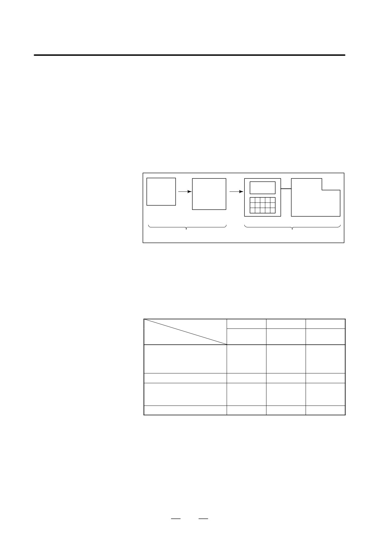
When machining the part using the CNC machine tool, first prepare the
program, then operate the CNC machine by using the program.
GENERAL FLOW
1) First, prepare the program from a part drawing to operate the CNC
OF OPERATION OF
machine tool.
CNC MACHINE
How to prepare the program is described in the Chapter II.
TOOL
PROGRAMMING.
2) The program is to be read into the CNC system. Then, mount the
workpieces and tools on the machine, and operate the tools according
to the programming. Finally, execute the machining actually.
How to operate the CNC system is described in the Chapter III.
OPERATION.
Part
Part
drawing
programming
CNC
MACHINE TOOL
CHAPTER II PROGRAMMING
CHAPTER III OPERATION
Before the actual programming, make the machining plan for how to
machine the part.
Machining plan
1. Determination of workpieces machining range
2. Method of mounting workpieces on the machine tool
3. Machining sequence in every machining process
4. Machining tools and machining
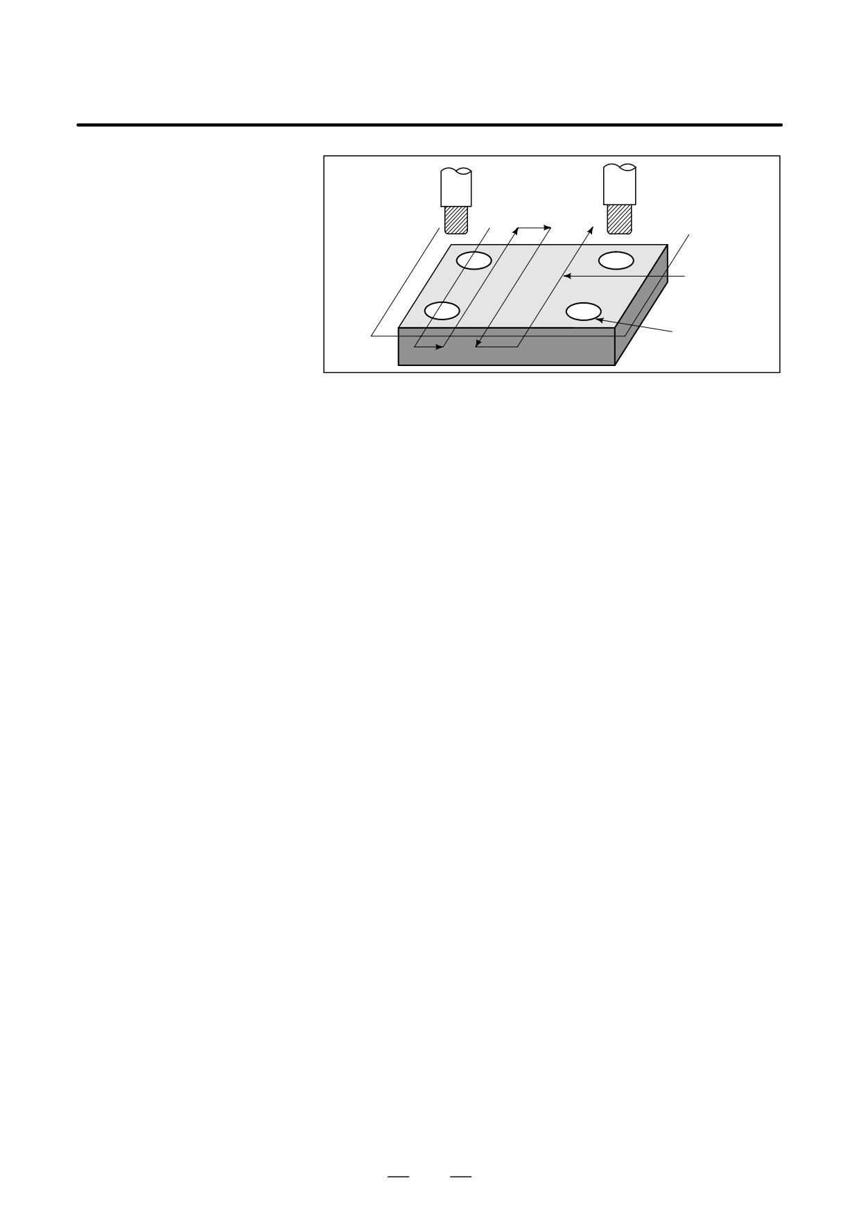
Decide the machining method in every machining process.
Machining process
1
2
3
Hole
Feed cutting
Side cutting
Machining procedure
machining
1. Machining method
: Rough
Semi
Finish
2. Machining tools
3. Machining conditions
: Feedrate
Cutting depth
4. Tool path
6
B-64124EN/01
GENERAL
1. GENERAL
Tool
Side cutting
Face cutting
Hole machining
Prepare the program of the tool path and machining condition
according to the workpiece figure, for each machining.
7
1. GENERAL
GENERAL
B-64124EN/01
1.2
CAUTIONS ON
CAUTION
READING THIS
1
The function of an CNC machine tool system depends not
MANUAL
only on the CNC, but on the combination of the machine
tool, its magnetic cabinet, the servo system, the CNC, the
operator ’s panels, etc. It is too difficult to describe the
function, programming, and operation relating to all
combinations. This manual generally describes these from
the stand-point of the CNC. So, for details on a particular
CNC machine tool, refer to the manual issued by the
machine tool builder, which should take precedence over
this manual.
2
Headings are placed in the left margin so that the reader can
easily access necessary information. When locating the
necessary information, the reader can save time by
searching though these headings.
3
This manual describes as many reasonable variations in
equipment usage as possible. It cannot address every
combination of features, options and commands that
should not be attempted.
If a particular combination of operations is not described, it
should not be attempted.
1.3
CAUTIONS ON
CAUTION
VARIOUS KINDS OF
Machining programs, parameters, variables, etc. are stored
DATA
in the CNC unit internal non-volatile memory. In general,
these contents are not lost by the switching ON/OFF of the
power. However, it is possible that a state can occur where
precious data stored in the non-volatile memory has to be
deleted, because of deletions from a maloperation, or by a
failure restoration. In order to restore rapidly when this kind
of mishap occurs, it is recommended that you create a copy
of the various kinds of data beforehand.
8
1. GENERAL
PROGRAMMING
B-64124EN/01
1.1
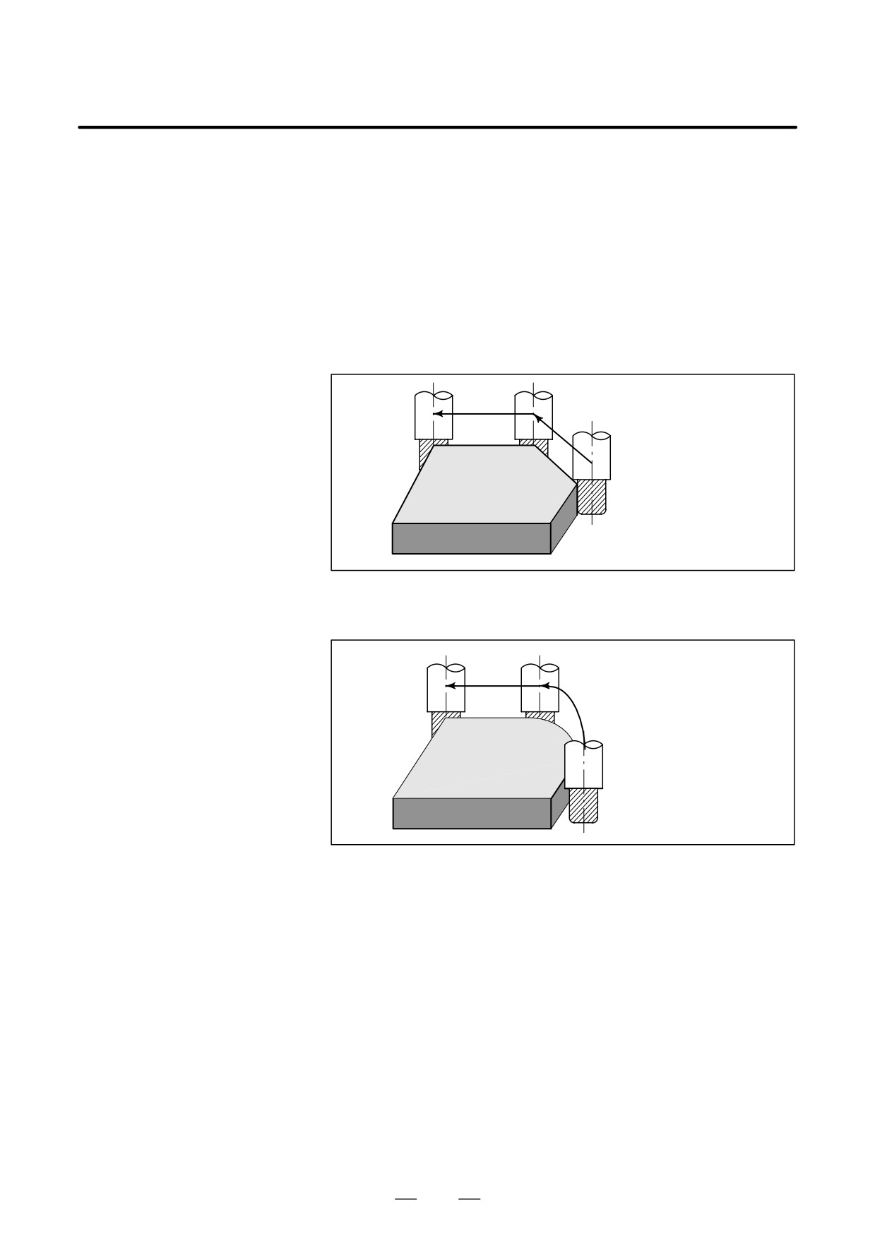
The tool moves along straight lines and arcs constituting the workpiece
parts figure (See II-4).
TOOL MOVEMENT
ALONG WORKPIECE
PARTS FIGURE-
INTERPOLATION
Explanations
The function of moving the tool along straight lines and arcs is called the
interpolation.
D Tool movement along a
straight line
Tool
Program
G01 X_ _ Y_ _ ;
X_ _ ;
Workpiece
Fig. 1.1 (a) Tool movement along a straight line
D Tool movement along an
arc
Program
G03X_ _Y_ _R_ _;
Tool
Workpiece
Fig. 1.1 (b) Tool movement along an arc
12
///////////////////////////////////////