FANUC Series 0i-MODEL D, Series 0i Mate-MODEL D. OPERATOR'S MANUAL - page 36

I.PC TOOL FOR MEMORY CARD
PROGRAM OPERATION/EDITING
APPENDIX
B-64304EN/02
File name that prevents drag-in
“O123456789”Numeric characters exceed 8 digits.
NOTE
1 Program file name cannot be repeated in a Folder.
2 If program file name starts with "O" and the next eight characters are all numeric
characters, the "0" (zero) after the "O" will be deleted.
I.2.2
Naming Rules of Folder
Here are Naming rules of Folder:
• Folder name can have a maximum of 32 characters.
• Folder name can have following characters.
Alphabet(Upper and lower case letter), numeric character,
"-"(minus), "+"(plus), "_"(under bar), "." (dot)
"." and ".." can not be used since these are reserved for system use.
NOTE
Folder name cannot be repeated in a Folder.
I.3
RULES OF CHARACTERS IN PROGRAM FILE
Overview
Words in parentheses "( )" in Program file are treated as comments.
The mark of comment start "(" is named "Control-out".
The mark of comment end ")" is named "Control-in".
"Control-out" and "Control-in" must make a pair. The order is 1st - "Control-out" and 2nd -"Control-in".
And nested parentheses is not available.
NOTE
1 When a program file is dragged in, space code (0x20 SPC) , tab code (0x09
HT) , carriage return code(0x0d CR) and percent code(0x25 %) is deleted. If "%"
is found in Control-in, characters between "%" and next "LF" (0x0a) is deleted.
2 The front of program number ":" is changed to "O"(O as in Oscar) while the
program file dragged in.
3 The program file can only have one NC program.
I.3.1
Usable Characters in Program File
- Usable characters in Control-in
List of ANSI(ASCII) codes of usable characters(hexadecimal form)
Code
Character
Code
Character
Code
Character
Code
Character
0a
LF
3f
?
58
X
74
t
23
#
40
@
59
Y
75
u
26
&
41
A
5a
Z
76
v
28
(
42
B
5b
[
77
w
29
)
43
C
5d
]
78
x
2a
44
D
5f
_
79
y
2b
+
45
E
61
a
7a
z
- 1026 -

I.PC TOOL FOR MEMORY CARD
B-64304EN/02
APPENDIX
PROGRAM OPERATION/EDITING
List of ANSI(ASCII) codes of usable characters(hexadecimal form)
Code
Character
Code
Character
Code
Character
Code
Character
2c
,
46
F
62
b
2d
-
47
G
63
c
2e
48
H
64
d
2f
/
49
I
65
e
30
0
4a
J
66
f
31
1
4b
K
67
g
32
2
4c
L
68
h
33
3
4d
M
69
i
34
4
4e
N
6a
j
35
5
4f
O
6b
k
36
6
50
P
6c
l
37
7
51
Q
6d
m
38
8
52
R
6e
n
39
9
53
S
6f
o
3a
:
54
T
70
p
3c
<
55
U
71
q
3d
=
56
V
72
r
3e
>
57
W
73
s
NOTE
In the Control-in, "O", ":", and "<" can not be used at top of the line except for the
1st line.
- Usable characters in Control-out(characters in parentheses)
List of ANSI(ASCII) codes of usable characters(hexadecimal form)
Code
Character
Code
Character
Code
Character
Code
Character
0a
LF
3c
<
55
U
71
q
20
SPC
3d
=
56
V
72
r
22
“
3e
>
57
W
73
s
23
#
3f
?
58
X
74
t
24
$
40
@
59
Y
75
u
26
&
41
A
5a
Z
76
v
27
‘
42
B
5b
[
77
w
2a
43
C
5d
]
78
x
2b
+
44
D
5f
_
79
y
2c
,
45
E
61
a
7a
z
2d
-
46
F
62
b
2e
47
G
63
c
2f
/
48
H
64
d
30
0
49
I
65
e
31
1
4a
J
66
f
32
2
4b
K
67
g
33
3
4c
L
68
h
34
4
4d
M
69
i
35
5
4e
N
6a
j
36
6
4f
O
6b
k
37
7
50
P
6c
l
38
8
51
Q
6d
m
39
9
52
R
6e
n
3a
:
53
S
6f
o
3b
;
54
T
70
p
- 1027 -

I.PC TOOL FOR MEMORY CARD
PROGRAM OPERATION/EDITING
APPENDIX
B-64304EN/02
I.4
ERROR MESSAGE AND NOTE
Error may occur when using this application, hereafter explains the error messages and gives relative
instructions.
I.4.1
List of Error Message
When an error occurred, the error message box is displayed as follows.
Message
Remarks
Failed to open the file you specified.
The memory card program file cannot be opened. When you retry
and the failure recurs, the file may be corrupt.
Failed to read or write to the specified file.
An attempt to read from or write to the memory card program file has
failed.
There is insufficient disk space.
There is not enough disk space for the work folder to create a
memory card program file or drag out a program file. Allocate
sufficient disk space, and then create a file.
See an explanation of [Change Work Folder] in "Explanation of
Operations".
File name is not correct.
The name cannot be used as a program file name. See "NAMING
RULES".
Input name is already exists.
The entered name is already used. Enter another name.
File name is already exists.
The added program file name already exists. Change the name.
Input name is not correct.
The entered name cannot be used. See "NAMING RULES".
Please input an integer between 2 and
A memory card program file cannot be created with the specified
2048
size. Enter a numeric value in the range of 2 to 2048.
An illegal character is included in the
An invalid character is included in the program file. See "RULES OF
specified file.
CHARACTERS IN PROGRAM FILE".
Last update time of the specified file is
The update time of the program file is beyond the range of years
unsupported.
(1997 to 2037) that can be supported by this PC tool. Create a new
file or change the update time.
The memory card program file you
The format of the memory card program file is not the format
specified cannot be identified.
supported by this PC tool. The file may be rewritten with some other
tool.
There is insufficient free folder.
A folder cannot be added. Delete unnecessary folders and program
files.
There is insufficient free program space.
A program file cannot be added. Delete unnecessary program files.
Folder deeper than 7 cannot be created.
An attempt was made to create a folder deeper than the 7th level.
Folders cannot be created deeper than the 7th level.
Root folder cannot be deleted.
An attempt was made to delete the root folder.
Root folder cannot be renamed.
An attempt was made to rename the root folder.
Failed to create work folder.
An attempt to create [temp] to be used as the work folder has failed.
Drag-out cannot be performed. Check whether the [temp] folder can
be created in the folder that contains the executable file
(FANUCPRG.exe).
Process has been cancelled.
Processing has been discontinued.
The specified work folder is not found.
The folder specified in the path is not found. Drag-out cannot be
performed. Exit this PC tool, and set the work folder again.
Only one instance of this application can be
More than one instance of this PC tool cannot be run.
executed.
- 1028 -
I.PC TOOL FOR MEMORY CARD
B-64304EN/02
APPENDIX
PROGRAM OPERATION/EDITING
I.4.2
Note
- Folder and Program Numbers
This PC tool allows you to select the number of folders or programs that can be stored in a memory card
program file; you can select 63, 500, or 1000. The number of folders or programs that can be used with
the 0i-D/0i Mate-D is 63, however.
If you select 500 or 1000 as the number of folders or programs when you create a memory card program
file, the 0i-D/0i Mate-D cannot use that memory card program file.
- 1029 -

J.ISO/ASCII CODE CONVERSION TOOLAPPENDIX
B-64304EN/02
J ISO/ASCII CODE CONVERSION TOOL
Overview
FANUC ISO Converter is a tool that converts a file created or externally output with ASCII code to ISO
code format.
This tool runs on Windows 2000, Windows XP, and Windows Vista.
This tool can be used in two modes, CUI and GUI.
CUI
Start the executable file from the command prompt.
Specify the following arguments when starting the tool.
/c : Specify that the tool runs in command line mode.
When /c is omitted, the tool runs in GUI mode.
/i= : Specify the name of an input file to be converted.
/o= :Specify the name of the converted file.
Example
C:¥>ISO_CONV.EXE /c /i=ALL-PROG.TXT /o=ALL-PROG.ISO
Multiple files can be converted at a time by listing them in a batch file.
- 1030 -
B-64304EN/02
APPENDIXJ.ISO/ASCII CODE CONVERSION TOOL
GUI
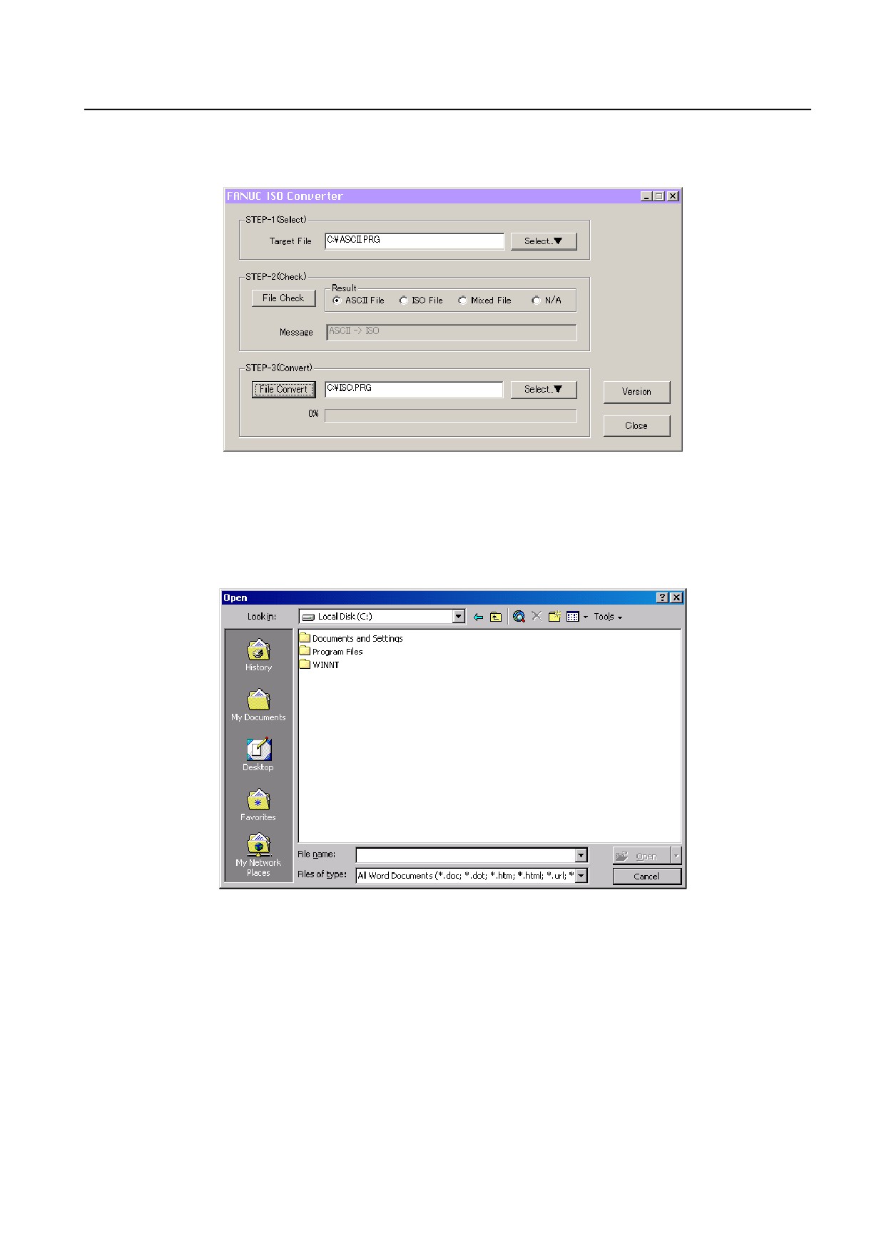
When you double-click the icon, the following screen appears, allowing you to select and convert a file.
Conversion procedure
1.
Step 1
In [Target File], specify a file you want to convert.
When you click the [Select...▼] button, a file selection dialogue appears, allowing you to select a
file.
2.
Step 2
After you specify the file name in step 1, you can determine the code of the specified file by clicking
the [File Check] button. When you select the file by clicking the [Select...▼] button, the code is
automatically determined.
The file is determined as an ASCII file, ISO file, or ASCII/ISO-mixed file, or is indeterminable. In
[Message], an additional message appears depending on the determination result.
If the file is determined as an ASCII/ISO-mixed file, it cannot be converted, so you cannot proceed
to the next step. The [File Convert] button is disabled and you cannot click it. If file contains only
characters represented by the code values common to ASCII and ISO, the code of the file is
indeterminable. This file need not be converted, so the [File Convert] button is disabled and you
cannot click it.
- 1031 -
J.ISO/ASCII CODE CONVERSION TOOLAPPENDIX
B-64304EN/02
3.
Step 3
When you specify the name of a converted file and click the [File Convert] button, the converted file
is created. When the original file is an ASCII file, an ISO file is created; when the original is an ISO
file, an ASCII file is created.
You can also click the [Select...▼] button and specify the name of the converted file from a file
selection dialogue.
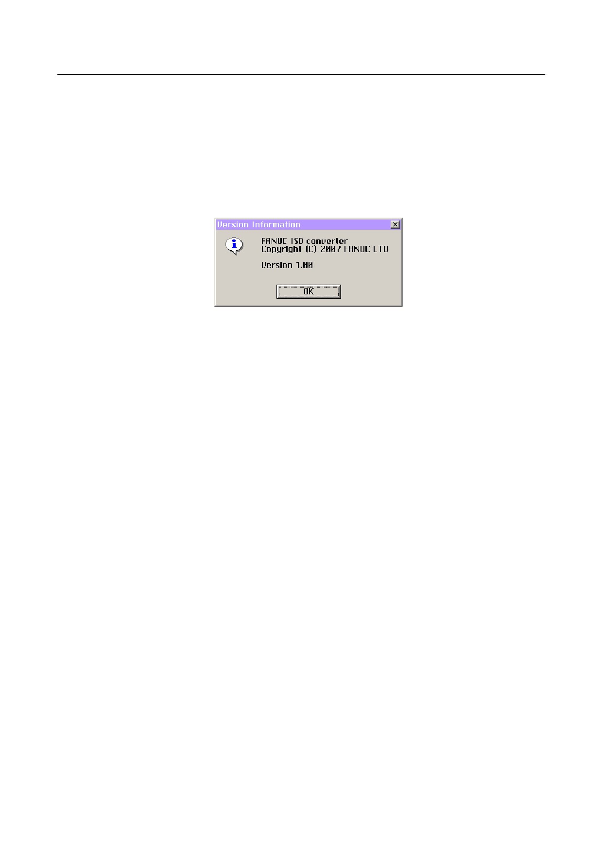
Other
When you click the [Version] button, the software version information is displayed as shown below.
- 1032 -
B-64304EN/02
APPENDIX K.DIFFERENCES FROM SERIES 0i-C
K DIFFERENCES FROM SERIES 0i-C
Appendix K, "Differences from Series 0i-C", consists of the following sections:
K.1
SETTING UNIT
1034
K.2
AUTOMATIC TOOL LENGTH MEASUREMENT (M SERIES)/AUTOMATIC TOOL
OFFSET (T SERIES)
1035
K.3
CIRCULAR INTERPOLATION
1038
K.4
HELICAL INTERPOLATION
1039
K.5
SKIP FUNCTION
1040
K.6
MANUAL REFERENCE POSITION RETURN
1042
K.7
WORKPIECE COORDINATE SYSTEM
1044
K.8
LOCAL COORDINATE SYSTEM
1045
K.9
Cs CONTOUR CONTROL
1046
K.10
MULTI-SPINDLE CONTROL
1047
K.11
SERIAL/ANALOG SPINDLE CONTROL
1047
K.12
CONSTANT SURFACE SPEED CONTROL
1048
K.13
SPINDLE POSITIONING (T SERIES)
1048
K.14
TOOL FUNCTIONS
1050
K.15
TOOL COMPENSATION MEMORY
1052
K.16
INPUT OF TOOL OFFSET VALUE MEASURED B (T SERIES)
1053
K.17
CUSTOM MACRO
1054
K.18
INTERRUPTION TYPE CUSTOM MACRO
1056
K.19
PROGRAMMABLE PARAMETER INPUT (G10)
1057
K.20
ADVANCED PREVIEW CONTROL (T SERIES)/AI ADVANCED PREVIEW CONTROL
(M SERIES)/AI CONTOUR CONTROL (M SERIES)
1057
K.21
MACHINING CONDITION SELECTION FUNCTION
1059
K.22
AXIS SYNCHRONOUS CONTROL
1060
K.23
ARBITRARY ANGULAR AXIS CONTROL
1065
K.24
RUN HOUR AND PARTS COUNT DISPLAY
1066
K.25
MANUAL HANDLE FEED
1067
K.26
PMC AXIS CONTROL
1068
K.27
EXTERNAL SUBPROGRAM CALL (M198)
1073
K.28
SEQUENCE NUMBER SEARCH
1074
K.29
STORED STROKE CHECK
1075
K.30
STORED PITCH ERROR COMPENSATION
1077
K.31
SCREEN ERASURE FUNCTION AND AUTOMATIC SCREEN ERASURE FUNCTION
1078
K.32
RESET AND REWIND
1079
K.33
MANUAL ABSOLUTE ON AND OFF
1079
K.34
MEMORY PROTECTION SIGNAL FOR CNC PARAMETER
1080
K.35
EXTERNAL DATA INPUT
1081
K.36
DATA SERVER FUNCTION
1083
K.37
POWER MATE CNC MANAGER
1083
K.38
CHUCK/TAIL STOCK BARRIER (T SERIES)
1084
K.39
THREADING CYCLE RETRACT (CANNED CUTTING CYCLE/MULTIPLE REPETITIVE
CANNED CUTTING CYCLE) (T SERIES)
1084
K.40
POLAR COORDINATE INTERPOLATION (T SERIES)
1085
K.41
PATH INTERFERENCE CHECK (T SERIES (2-PATH CONTROL))
1087
K.42
SYNCHRONOUS CONTROL AND COMPOSITE CONTROL (T SERIES (2-PATH
CONTROL))
1087
K.43
SUPERIMPOSED CONTROL (T SERIES (2-PATH CONTROL))
1091
K.44
Y AXIS OFFSET (T SERIES)
1093
K.45
CUTTER COMPENSATION/TOOL NOSE RADIUS COMPENSATION
1093
- 1033 -

K.DIFFERENCES FROM SERIES 0i-C APPENDIX
B-64304EN/02
K.46 CANNED CYCLE FOR DRILLING
1100
K.47 CANNED CYCLE (T SERIES)/MULTIPLE REPETITIVE CANNED CYCLE (T SERIES) ...1102
K.48 CANNED GRINDING CYCLE
1103
K.49 MULTIPLE RESPECTIVE CANNED CYCLE FOR TURNING (T SERIES)
1104
K.50 CHAMFERING AND CORNER ROUNDING (T SERIES)
1108
K.51 DIRECT DRAWING DIMENSIONS PROGRAMMING (T SERIES)
1109
K.52 SINGLE DIRECTION POSITIONING (M SERIES)
1109
K.53 OPTIONAL ANGLE CHAMFERING AND CORNER ROUNDING (M SERIES)
1110
K.1 SETTING UNIT
K.1.1 Differences in Specifications
Function
Explanation
Diameter/radius
-
Make a selection using bit 3 (DIAx) of parameter No. 1006.
specification in the
move command for
Bit 3 (DIAx) of parameter No. 1006
each axis
The move command for each axis specifies:
0: Radius.
1: Diameter.
With Series 0i-C, in order for an axis whose diameter is specified to travel the specified
distance, it is necessary not only to set 1 in bit 3 (DIAx) of parameter No. 1006 but also to
make either of the following two changes:
-
Reduce the command multiplier (CMR) to half.
(The detection unit does not need to
be changed.)
-
Reduce the detection unit to half, and double the flexible feed gear (DMR).
With Series 0i-D, by contrast, just setting 1 in bit 3 (DIAx) of parameter No. 1006 causes
the CNC to reduce the command pulses to half, eliminating the need to make the
changes described above (when the detection unit is not changed).
Note that, when the detection unit is reduced to half, both the CMR and DMR need to be
doubled.
K.1.2 Differences in Diagnosis Display
None.
- 1034 -

B-64304EN/02
APPENDIX K.DIFFERENCES FROM SERIES 0i-C
K.2 AUTOMATIC TOOL LENGTH MEASUREMENT (M
SERIES)/AUTOMATIC TOOL OFFSET (T SERIES)
M
K.2.1 Automatic Tool Length Measurement (M Series)
K.2.1.1 Differences in Specifications
Function
Series 0i-C
Series 0i-D
Operation of the
-
Added to the current offset.
-
Select whether to add or subtract, by
current offset for the
using bit 6 (MDC) of parameter No.
measurement result
6210.
Bit 6 (MDC) of parameter No. 6210
The measurement result of automatic tool
length measurement (system M) or
automatic tool compensation (system T) is:
0: Added to the current offset.
1: Subtracted from the current offset.
Setting of the feedrate
-
Set the value in parameter No. 6241.
-
Parameter No. 6241
for measurement
This is a parameter common to the
This is a parameter for the measuring
measuring position reached signals
position reached signals (XAE1 and
(XAE, YAE, and ZAE).
GAE1).
-
Parameter No. 6242
This is a parameter for the measuring
position reached signals (XAE2 and
GAE2).
-
Parameter No. 6243
This is a parameter for the measuring
position reached signals (XAE3 and
GAE3).
NOTE
When 0 is set in parameter Nos. 6242 and
6243, the value in parameter No. 6241
becomes valid.
Setting of the γ value
-
Set the value in parameter No. 6251.
-
Parameter No. 6251
This is a parameter common to the
This is a parameter for the measuring
measuring position reached signals
position reached signals (XAE1 and
(XAE, YAE, and ZAE).
GAE1).
-
Parameter No. 6252
This is a parameter for the measuring
position reached signals (XAE2 and
GAE2).
-
Parameter No. 6253
This is a parameter for the measuring
position reached signals (XAE3 and
GAE3).
NOTE
When 0 is set in parameter Nos. 6252 and
6253, the value in parameter No. 6251
becomes valid.
- 1035 -

K.DIFFERENCES FROM SERIES 0i-C APPENDIX
B-64304EN/02
Function
Series 0i-C
Series 0i-D
Setting of the ε value
-
Set the value in parameter No. 6254.
-
Parameter No. 6254
This is a parameter common to the
This is a parameter for the measuring
measuring position reached signals
position reached signals (XAE1 and
(XAE, YAE, and ZAE).
GAE1).
-
Parameter No. 6255
This is a parameter for the measuring
position reached signals (XAE2 and
GAE2).
-
Parameter No. 6256
This is a parameter for the measuring
position reached signals (XAE3 and
GAE3).
NOTE
When 0 is set in parameter Nos. 6255 and
6256, the value in parameter No. 6254
becomes valid.
K.2.1.2 Differences in Diagnosis Display
None.
T
K.2.2 Automatic Tool Offset (T Series)
K.2.2.1 Differences in Specifications
Function
Series 0i-C
Series 0i-D
Operation of the
-
Added to the current offset.
-
Select whether to add or subtract, by
current offset for the
using bit 6 (MDC) of parameter No.
measurement result
6210.
Bit 6 (MDC) of parameter No. 6210
The measurement result of automatic tool
length measurement (system M) or
automatic tool compensation (system T) is:
0: Added to the current offset.
1: Subtracted from the current offset.
Setting of the feedrate
-
Set the value in parameter No. 6241.
-
Parameter No. 6241
for measurement
This is a parameter common to the
This is a parameter for the measuring
measuring position reached signals
position reached signals (XAE1 and
(XAE and ZAE).
GAE1).
-
Parameter No. 6242
This is a parameter for the measuring
position reached signals (XAE2 and
GAE2).
NOTE
When 0 is set in parameter No. 6242, the
value in parameter No. 6241 becomes valid.
- 1036 -

B-64304EN/02
APPENDIX K.DIFFERENCES FROM SERIES 0i-C
Function
Series 0i-C
Series 0i-D
Setting of the γ value
-
Set the value in parameter No. 6251.
-
Parameter No. 6251
for the X axis
This is a parameter common to the
This is a parameter for the measuring
measuring position reached signals
position reached signals (XAE1 and
(XAE and ZAE).
GAE1).
-
Parameter No. 6252
This is a parameter for the measuring
position reached signals (XAE2 and
GAE2).
NOTE
When 0 is set in parameter No. 6252, the
value in parameter No. 6251 becomes valid.
Setting of the ε value
-
Set the value in parameter No. 6254.
-
Parameter No. 6254
for the X axis
This is a parameter common to the
This is a parameter for the measuring
measuring position reached signals
position reached signals (XAE1 and
(XAE and ZAE).
GAE1).
-
Parameter No. 6255
This is a parameter for the measuring
position reached signals (XAE2 and
GAE2).
NOTE
When 0 is set in parameter No. 6255, the
value in parameter No. 6254 becomes valid.
K.2.2.2 Differences in Diagnosis Display
None.
- 1037 -
K.DIFFERENCES FROM SERIES 0i-C APPENDIX
B-64304EN/02
K.3 CIRCULAR INTERPOLATION
K.3.1 Differences in Specifications
Function
Series 0i-C
Series 0i-D
Interpolation method
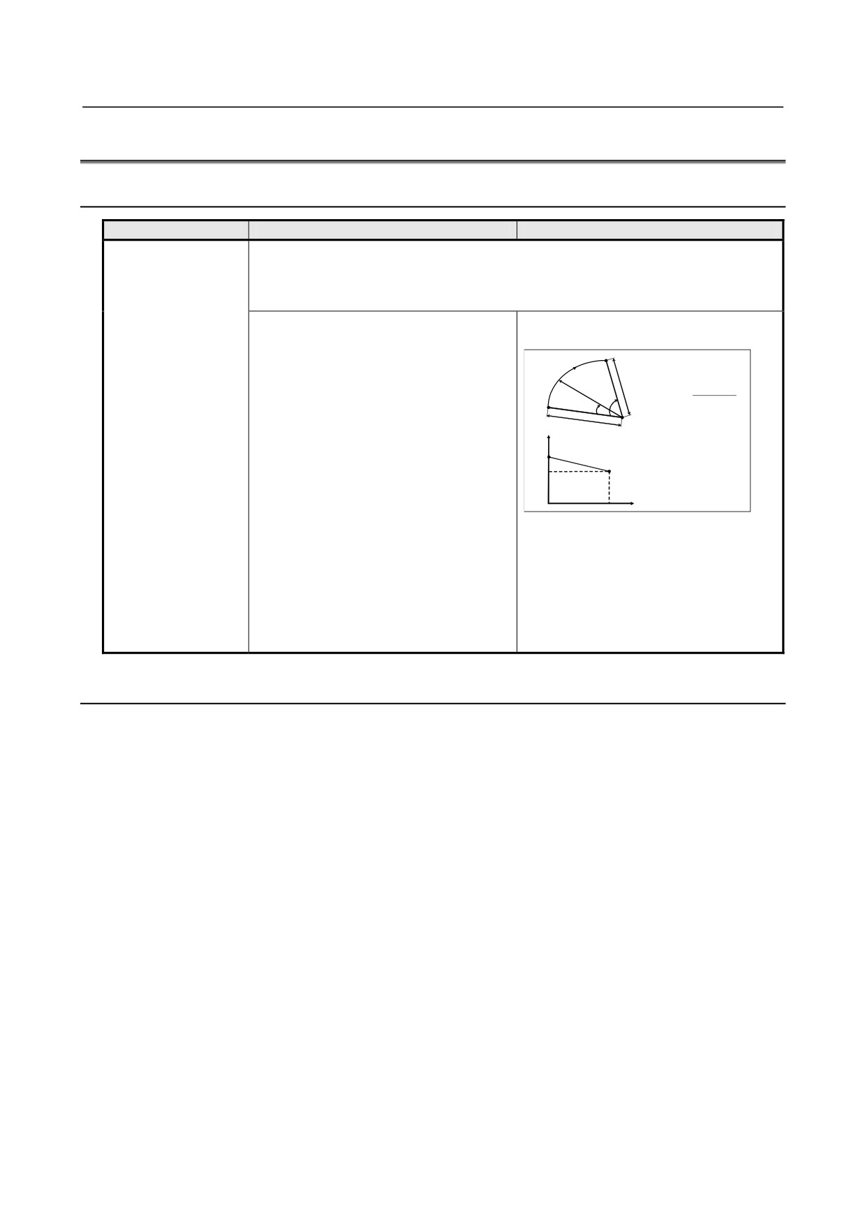
If the difference between the radius values of the start point and end point of an arc is
when the arc end
greater than the value set in parameter No. 3410, alarm PS0020 is issued. If the
point is not on the arc
difference is smaller (the end point is not on the arc), circular interpolation is performed as
follows.
-
Circular interpolation is performed
-
Helical interpolation is performed as
using the radius value of the start point
shown in the figure below.
End point
and, when an axis reaches the end
point, it is moved linearly.
γe
γ(t)
(γe
−γs)θ
(t
)
γ(t)
=γs
+
Start
θ
θ
θ(t)
Parameter No. 3410
point
γs
中心
In a circular interpolation command, set the
Radius
limit allowed for the difference between the
Start point
γs
radius values of the start point and end
γe
End point
point.
Center θ
θ
In other words, the radius of the arc moves
linearly according to the center angle θ(t).
Specifying an arc where the arc radius of
the start point differs from that of the end
point enables helical interpolation. When
performing helical interpolation, set a large
value in parameter No. 3410 that specifies
the limit for the arc radius difference.
K.3.2 Differences in Diagnosis Display
None.
- 1038 -

B-64304EN/02
APPENDIX K.DIFFERENCES FROM SERIES 0i-C
K.4 HELICAL INTERPOLATION
K.4.1 Differences in Specifications
Function
Series 0i-C
Series 0i-D
Specification of the
-
Specify the feedrate along a circular
-
Make a selection using bit 5 (HTG) of
feedrate
arc. Therefore, the feedrate of the
parameter No. 1403.
linear axis is as follows:
0: Same as left.
1: Specify a feedrate along the tool path
Length of linear axis
including the linear axis. Therefore, the
F ×
tangential velocity of the arc is expressed
Length of circular arc
as follows:
Length of arc
F×
(Length of arc)2+(Length of linear axis)2
The velocity along the linear axis is expressed
as follows:
Length of linear axis
F×
(Length of arc)2+(Length of linear axis)2
For details, refer to "HELICAL
INTERPOLATION" in "CONNECTION
MANUAL (FUNCTION)" (B-64303EN-1).
Helical cutting
-
Make a selection using bit 0 (HFC)
-
Bit 0 (HFC) of parameter No. 1404 is not
feedrate clamp
of parameter No. 1404.
available.
0: The feedrate of the arc and
The feedrate of the arc and linear axes is
linear axes is clamped by
clamped by parameter No. 1430.
parameter No. 1422 or
No.1430.
1: The combined feedrate along
the tool path including the
linear axis is clamped by
parameter No. 1422.
K.4.2 Differences in Diagnosis Display
None.
- 1039 -
K.DIFFERENCES FROM SERIES 0i-C APPENDIX
B-64304EN/02
K.5 SKIP FUNCTION
K.5.1 Differences in Specifications
Function
Series 0i-C
Series 0i-D
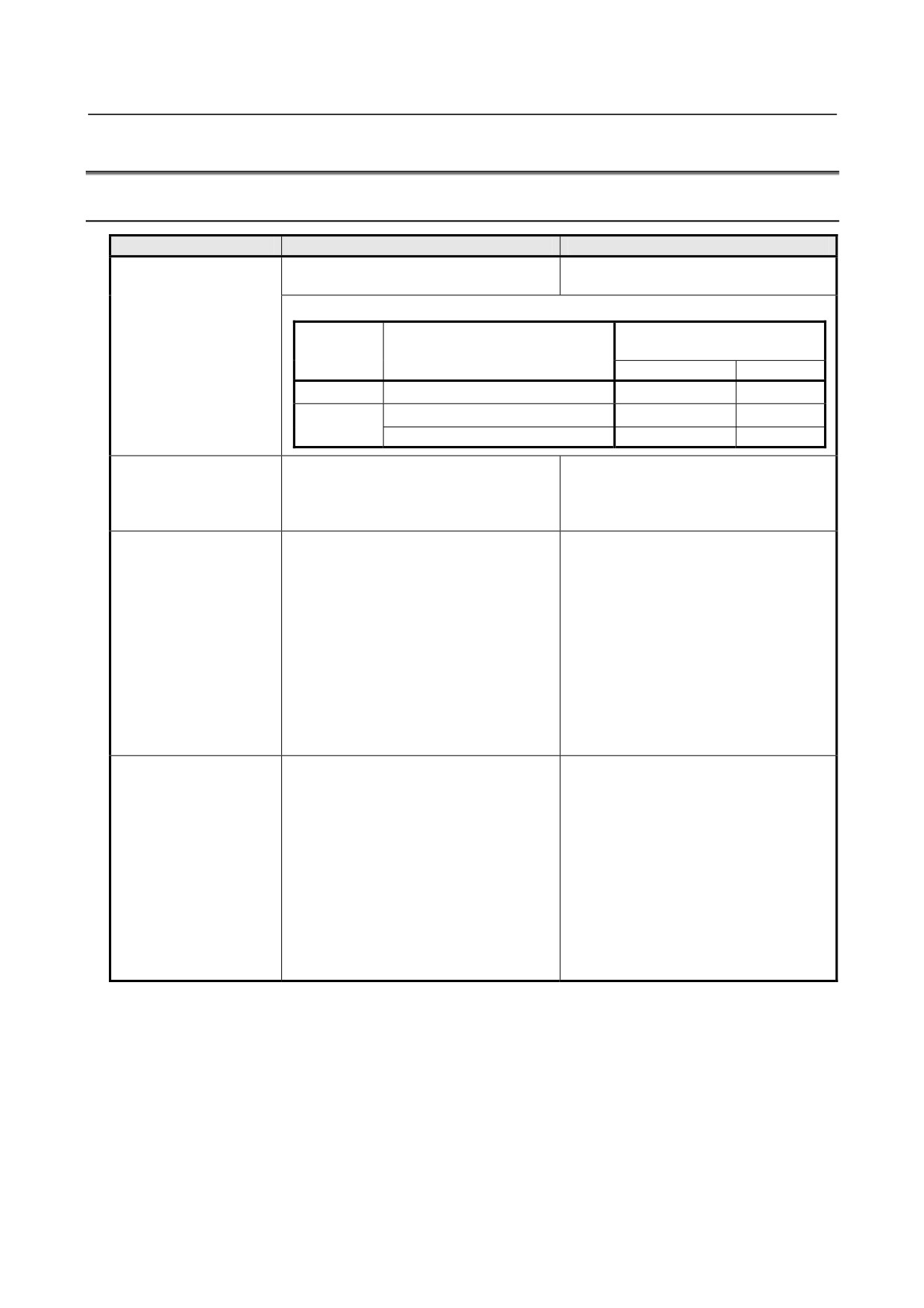
Setting to enable the
-
Set 1 in bit 5 (SLS) of parameter No.
-
Set 1 in bit 4 (HSS) of parameter No.
high-speed skip signal
6200.
6200.
for normal skip (G31)
when the multi-stage
Multi-stage
Parameter to decide on use
skip function is enabled
skip
Command
of the high-speed skip signal
function
FS0i-C
FS0i-D
Disabled
G31 (normal skip)
HSS
HSS
G31 (normal skip)
SLS
HSS
Enabled
G31P1 to G31P4 (multi-stage skip)
SLS
SLS
Target of
-
Compensation is performed for the
-
Compensation is performed for the
acceleration/deceleration
skip coordinates obtained when the
skip coordinates obtained when the
and servo system delay
high-speed skip signal is set to "1".
skip or high-speed skip signal is set
compensation
to "1".
Method of
-
There are two ways to perform
-
Bit 0 (SEA) of parameter No. 6201 is
acceleration/deceleration
compensation, as follows.
not available.
and servo system delay
[Compensating the value calculated
There is only one way to perform
compensation
from the cutting constant and servo
compensation, as follows.
constant]
[Compensating the accumulated
Set 1 in bit 0 (SEA) of parameter No.
pulses and positional deviation due to
6201.
acceleration/deceleration]
[Compensating the accumulated
Set 1 in bit 1 (SEB) of parameter No.
pulses and positional deviation due to
6201.
acceleration/deceleration]
Set 1 in bit 1 (SEB) of parameter No.
6201.
Skip cutting feedrate
-
Feedrate specified by the F code in
-
Depends on bit 1 (SFP) of parameter
(normal skip)
the program
No. 6207. When 0 is set, the
processing is the same as Series
0i-C.
Bit 1 (SFP) of parameter No. 6207
The feedrate during the skip function
(G31) is:
0: Feedrate specified by the F code in
the program.
1: Feedrate specified in parameter No.
6281.
- 1040 -

B-64304EN/02
APPENDIX K.DIFFERENCES FROM SERIES 0i-C
Function
Series 0i-C
Series 0i-D
Skip cutting feedrate
-
Feedrate specified by the F code in
-
Depends on bit 2 (SFN) of parameter
(skip using the
the program
No. 6207. When 0 is set, the
high-speed skip signal or
processing is the same as Series
multi-step skip)
0i-C.
Bit 2 (SFP) of parameter No. 6207
When the skip function using the
high-speed skip signal (1 is set in bit 4
(HSS) of parameter No. 6200) or the
multi-step skip function is executed, the
feedrate is:
0: Feedrate specified by the F code in
the program.
1: Feedrate specified in parameter Nos.
6282 to 6285.
Axis to monitor to check
-
Depends on bit 3 (TSA) of parameter
-
Bit 3 (TSA) of parameter No. 6201 is
whether the torque limit
No. 6201.
not available.
has been reached
Only the axis specified in the same
(torque limit skip)
Bit 3 (TSA) of parameter No. 6201
block as G31 P99/98 is monitored.
To check whether the torque limit has
been reached, the torque limit skip
function (G31 P99/98) monitors:
0: All axes.
1: Only the axis specified in the same
block as G31 P99/98.
High-speed skip signal
As the skip signal for the G31 P99 command, the high-speed skip signal:
input for the G31 P99
-
Cannot be input.
-
Can be input.
command
(torque limit skip)
Setting of a positional
-
No parameter is available dedicated
-
The value can be set in parameter
deviation limit in the
to setting a positional deviation limit
No. 6287.
torque limit skip
for the torque limit skip function.
command
Parameter No. 6287
(torque limit skip)
Set a positional deviation limit in the
torque limit skip command for each axis.
When G31 P99/98 is
-
The G31 P99/98 command is
-
Alarm PS0035 is issued.
specified without a
executed as is.
torque limit being
(No alarm is issued.)
specified in advance
(torque limit skip)
K.5.2 Differences in Diagnosis Display
None.
- 1041 -

K.DIFFERENCES FROM SERIES 0i-C APPENDIX
B-64304EN/02
K.6 MANUAL REFERENCE POSITION RETURN
K.6.1 Differences in Specifications
Function
Series 0i-C
Series 0i-D
Conditions for
Manual reference position return is performed when automatic operation is halted (feed
performing manual
hold) and when any of the following conditions is met:
reference position
<Conditions>
return during feed
(1) Travel distance is remaining.
hold
(2) An auxiliary function (M, S, T, or B function) is being executed.
(3) A dwell, canned cycle, or other cycle is in progress.
-
Depends on bit 2 (OZR) of parameter
-
Bit 2 (OZR) of parameter No. 1800 is
No. 1800.
not available.
[When OZR = 0]
Alarm PS0091 occurs, and manual
Alarm PS0091 occurs, and manual
reference position return is not
reference position return is not
performed.
performed.
[When OZR = 1]
Manual reference position return is
performed without issuing an alarm.
When inch/metric
-
The reference position is lost.
-
The reference position is not lost.
switch is done
(The reference position is not
(The reference position remains
established.)
established.)
Reference position
-
Set 1 in bit 1 (DLZ) of parameter No.
-
Bit 1 (DLZ) of parameter No. 1002 is
setting without dogs
1002.
not available.
for all axes
Reference position setting without
dogs (bit 1 (DLZx) of parameter No.
1005) is set for all axes.
Function that performs
-
Not available.
-
Depends on bit 4 (GRD) of parameter
reference position
No. 1007.
setting without dogs
two or more times
Bit 4 (GRD) of parameter No. 1007
when the reference
For the axis on which absolute values are
position is not
detected, when correspondence between
established in
the machine position and the position by
absolute position
the absolute position detector is not
detection
completed, the reference position setting
without dogs is:
0: Not performed two or more times.
1: Performed two or more times.
- 1042 -
B-64304EN/02
APPENDIX K.DIFFERENCES FROM SERIES 0i-C
Function
Series 0i-C
Series 0i-D
Behavior when
T
-
[Rotation axis type = A and bit 0
manual reference
-
[When bit 0 (RTLx) of parameter No.
(RTLx) of parameter No. 1007 = 0]
position return is
1007 = 0]
Movement is made at the reference
started on a rotation
Movement is made at the rapid
position return feedrate FL even if the
axis with the
traverse feedrate until the grid is
grid is not established.
deceleration dog
established.
Releasing the deceleration dog before
pressed before a
If the deceleration dog is released
the grid is established causes alarm
reference position is
before the grid is established, one
PS0090.
established
revolution is made at the rapid traverse
[Rotation axis type = A and bit 0
feedrate, thus establishing the grid.
(RTLx) of parameter No. 1007 = 1]
Pressing the deceleration dog again
Movement is made at the rapid
establishes the reference position.
traverse feedrate until the grid is
[When bit 0 (RTLx) of parameter No.
established.
1007 = 1]
If the deceleration dog is released
Movement is made at the reference
before the grid is established, one
position return feedrate FL even if the
revolution is made at the rapid traverse
grid is not established.
feedrate, thus establishing the grid.
Releasing the deceleration dog before
Pressing the deceleration dog again
the grid is established causes alarm
establishes the reference position.
PS0090.
[Rotation axis type = B]
M
Does not depend on bit 0 (RTLx) of
-
Does not depend on bit 0 (RTLx) of
parameter No. 1007.
parameter No. 1007.
Movement is made at the reference
Movement is made at the reference
position return feedrate FL even if the
position return feedrate FL even if the
grid is not established.
grid is not established.
Releasing the deceleration dog before
Releasing the deceleration dog before
the grid is established causes alarm
the grid is established causes alarm
PS0090.
PS0090.
Reference position
-
Available only for the M series in Series
-
Available for all series in Series 0i-D.
shift function
0i-C and earlier.
Reference position
-
The function is enabled for all axes by
-
Bit 2 (SFD) of parameter No. 1002 is
shift function setting
setting 1 in bit 2 (SFD) of parameter
not available.
No. 1002.
Set bit 4 (SFDx) of parameter No.
1008 for each axis.
Setting of whether to
-
Not available.
-
Depends on bit 1 (HZP) of parameter
preset the coordinate
The coordinate system is not preset.
No. 1206.
system upon
high-speed manual
Bit 1 (HZP) of parameter No.1206
reference position
Upon high-speed manual reference
return
position return, the coordinate system is:
0: Preset.
1: Not preset (FS0i-C compatible
specification).
- 1043 -

K.DIFFERENCES FROM SERIES 0i-C APPENDIX
B-64304EN/02
M
Function
Series 0i-C
Series 0i-D
G28/G30 command in
-
Not available.
-
The command can be executed only
the coordinate system
Cancel the mode before executing the
when all of the conditions described
rotation, scaling, or
command.
below are met.
programmable mirror
Otherwise, alarm PS0412 occurs.
image mode
<Conditions>
[Conditions required before specifying the
command]
(1) An absolute command is specified for
the target axis of coordinate system
rotation, scaling, or programmable
mirror image.
(2) Tool length compensation has not
been performed for the target axis of
coordinate system rotation, scaling, or
programmable mirror image when it is
moved by reference position return.
(3) Tool length compensation has been
canceled.
[Conditions required when specifying the
command]
(4) In an incremental command, the travel
distance of the middle point is 0.
[Conditions required after specifying the
command]
(5) The first move command specified for
the target axis of coordinate system
rotation, scaling, or programmable
mirror image is an absolute command.
K.6.2
Differences in Diagnosis Display
None.
K.7
WORKPIECE COORDINATE SYSTEM
K.7.1
Differences in Specifications
Function
Series 0i-C
Series 0i-D
Change in absolute
-
Make a selection using bit 5 (AWK) of parameter
-
Bit 5 (AWK) of parameter
position display when
No. 1201.
No. 1201 is not available.
the workpiece zero
The tool always behaves
Bit 5 (AWK) of parameter No. 1201
point offset value is
as when AWK is set to 1.
When the workpiece zero point offset value is changed:
changed
0: Changes the absolute position display when the
program executes the block that is buffered next.
1: Changes the absolute position display immediately.
In either case, the changed value does not take effect
until the block that is buffered next.
K.7.2 Differences in Diagnosis Display
None.
- 1044 -

B-64304EN/02
APPENDIX K.DIFFERENCES FROM SERIES 0i-C
K.8 LOCAL COORDINATE SYSTEM
K.8.1 Differences in Specifications
Function
Series 0i-C
Series 0i-D
Clearing of the local
-
The processing is
-
The processing is determined by the settings of bit
coordinate system
determined by the settings
7 (WZR) of parameter No. 1201, bit 3 (RLC) of
after servo alarm
of bit 5 (SNC) and bit 3
parameter No. 1202, bit 6 (CLR) of parameter No.
cancellation
(RLC) of parameter No.
3402, and bit 6 (C14) of parameter No. 3407.
1202.
Bit 5 (SNC) of parameter No. 1202 is not available.
Bit 3 (RLC) of parameter No.
Bit 7 (WZR) of parameter No. 1201
1202
If the CNC is reset by the reset key on the MDI panel,
Upon reset, the local
external reset signal, reset and rewind signal, or
coordinate system is:
emergency stop signal when bit 6 (CLR) of parameter
0: Not canceled.
No. 3402 is set to 0, the G code of group number 14
1: Canceled.
(workpiece coordinate system) is:
0: Placed in the reset state.
Bit 5 (SNC) of parameter No.
1: Not placed in the reset state.
1202
NOTE
After servo alarm cancellation,
When bit 6 (CLR) of parameter No. 3402 is set to 1, the
the local coordinate system is:
processing depends on the setting of bit 6 (C14) of
0: Cleared.
parameter No. 3407.
1: Not cleared.
NOTE
Bit 3 (RLC) of parameter No. 1202
When the RLC bit of the
Upon reset, the local coordinate system is:
parameter is set to 1, the local
0: Not canceled.
coordinate system is cleared,
1: Canceled.
even if the SNC bit of the
NOTE
parameter is set to 1.
-
When bit 6 (CLR) of parameter No. 3402 is set to 0
and bit 7 (WZR) of parameter No. 1201 is set to 1,
the local coordinate system is canceled, regardless
of the setting of this parameter.
-
When bit 6 (CLR) of parameter No. 3402 is set to 1
and bit 6 (C14) of parameter No. 3407 is set to 0,
the local coordinate system is canceled, regardless
of the setting of this parameter.
Bit 6 (CLR) of parameter No. 3402
The reset key on the MDI panel, external reset signal,
reset and rewind signal, or emergency stop signal
places the local coordinate system in:
0: Reset state.
1: Clear state.
Bit 6 (C14) of parameter No. 3407
If the CNC is reset by the reset key on the MDI panel,
external reset signal, reset and rewind signal, or
emergency stop signal when bit 6 (CLR) of parameter
No. 3402 is set to 1, the G code of group number 14
(workpiece coordinate system) is:
0: Placed in the clear state.
1: Not placed in the clear state.
- 1045 -

K.DIFFERENCES FROM SERIES 0i-C APPENDIX
B-64304EN/02
M
Function
Series 0i-C
Series 0i-D
Operation with the
-
Make a selection using bit 4 (G52) of
-
Bit 4 (G52) of parameter No. 1202 is
local coordinate
parameter No. 1202.
not available.
system setting (G52)
The tool always behaves as when G52
Bit 4 (G52) of parameter No. 1202
is set to 1.
1) If there are two or more blocks that are
not moved before G52 is specified
during cutter compensation, or if G52 is
specified after the cutter compensation
mode is turned off, with the offset
vector maintained, the local coordinate
system setting is performed:
0: Without considering the cutter
compensation vector.
1: Considering the cutter
compensation vector.
2) When G52 is specified, the local
coordinate system setting is performed
for:
0: All axes.
1: Only those axes whose command
addresses are found in the
G52-specified block.
K.8.2
Differences in Diagnosis Display
None.
K.9
Cs CONTOUR CONTROL
K.9.1
Differences in Specifications
Function
Series 0i-C
Series 0i-D
In-position check
-
The in-position check is not made.
-
Make a selection using bit 2 (CSNs) of
when the Cs contour
parameter No. 3729.
control mode is off
Bit 2 (CSNs) of parameter No. 3729
When the Cs contour control mode is off,
the in-position check is:
0: Made.
1: Not made.
When 1 is set in this parameter, the
processing is the same as Series 0i-C.
K.9.2 Differences in Diagnosis Display
Item
Series 0i-C
Series 0i-D
Position error display
For the first spindle, diagnosis display No.
For both the first and second spindles,
for Cs contour control
418 is used.
diagnosis display No. 418 (spindle) is used.
For the second spindle, diagnosis display
No. 420 is used.
- 1046 -

B-64304EN/02
APPENDIX K.DIFFERENCES FROM SERIES 0i-C
K.10 MULTI-SPINDLE CONTROL
T
K.10.1 Differences in Specifications
Function
Series 0i-C
Series 0i-D
Number of gear
-
The first spindle has four stages. Set
-
Both the first and second spindles
stages for each
the maximum spindle speeds for the
each have four stages. Set the
spindle
individual gears in parameter Nos.
maximum spindle speeds for the
3741 to 3744, respectively.
individual gears in parameter Nos.
-
The second spindle has two stages.
3741 to 3744, respectively.
Set the maximum spindle speeds for
(The data type of parameter Nos. 3741
the individual gears in parameter No.
to 3744 is spindle.)
3811 and 3812.
Spindle override when
When the override function is used for each axis in multi-spindle control type C, the
the override function
following spindle override specifications apply during the tapping cycle mode (G84 or
is used for each axis
G88) or threading mode (G32, G92, or G76).
in multi-spindle control
-
No function is available to clamp
-
Depends on bit 6 (TSO) of parameter
type C
spindle override to 100%.
(It does not
No. 3708.
depend on bit 6 (TSO) of parameter
No. 3708.)
Bit 6 (TSO) of parameter No. 3708
Modify the ladder code as necessary.
During the threading or tapping cycle,
spindle override is:
0: Disabled (clamped to 100%).
1: Enabled.
K.10.2 Differences in Diagnosis Display
None.
K.11 SERIAL/ANALOG SPINDLE CONTROL
K.11.1 Differences in Specifications
Function
Series 0i-C
Series 0i-D
Spindle number of the
-
When one serial spindle and one analog spindle are simultaneously controlled in one
analog spindle
path (serial/analog spindle control), the spindle number of the analog spindle is as
follows.
Third spindle
Second spindle
For details about the parameters and other
settings, refer to "SERIAL/ANALOG
SPINDLE CNOTROL" in "CONNECTION
MANUAL (FUNCTION)" (B-64303EN-1).
K.11.2 Differences in Diagnosis Display
None.
- 1047 -

K.DIFFERENCES FROM SERIES 0i-C APPENDIX
B-64304EN/02
K.12 CONSTANT SURFACE SPEED CONTROL
K.12.1 Differences in Specifications
Function
Series 0i-C
Series 0i-D
Constant surface
-
This is an optional function for the T
-
This is a basic function for both M
speed control with no
series.
series and T series.
position coder
It is not available with the M series.
It can be used by enabling constant
surface speed control (setting 1 in bit 0
(SSC) of parameter No. 8133) and
setting 1 in bit 2 (PCL) of parameter
No. 1405.
-
Using bit 0 (PSSCL) of parameter No.
-
Bit 0 (PSSCL) of parameter No. 1407
1407, select whether to enable or
is not available.
disable the axis feedrate clamp in feed
The axis feedrate is always clamped.
per revolution when the spindle speed
Using the position coder selection
is clamped by the maximum spindle
signal, select the spindle to be used for
speed set in parameter No. 3772.
feed per revolution.
(To use the
position coder selection signal requires
Bit 0 (PSSCL) of parameter No. 1407
enabling multi-spindle control.)
In constant surface speed control with no
position coder, when the spindle speed is
clamped by the maximum spindle speed
parameter, the axis feedrate in feed per
revolution is:
0: Not clamped.
1: Clamped.
When 1 is set in this parameter, select the
spindle to be used for feed per revolution
by using the position coder selection signal.
(To use the position coder selection signal
requires enabling multi-spindle control.)
K.12.2
Differences in Diagnosis Display
None.
K.13
SPINDLE POSITIONING (T SERIES)
T
K.13.1
Differences in Specifications
Function
Series 0i-C
Series 0i-D
Display unit of
-
Pulses
-
Make a selection using bit 0 (DMD) of
machine coordinates
parameter No. 4959.
on the spindle
positioning axis
Bit 0 (DMD) of parameter No. 4959
A machine coordinate on the spindle
positioning axis is displayed in:
0: Degrees.
1: Pulses.
- 1048 -

B-64304EN/02
APPENDIX K.DIFFERENCES FROM SERIES 0i-C
Function
Series 0i-C
Series 0i-D
Spindle positioning
-
Not available.
-
Spindle positioning using the second
using the second
spindle is possible when multi-spindle
spindle
control is enabled.
Number of M codes
-
Make a selection using bit 6 (ESI) of
-
Regardless of the setting of bit 6 (ESI)
for specifying the
parameter No. 4950.
of parameter No. 4950, the setting of
spindle positioning
parameter No. 4964 takes effect.
angle
Bit 6 (ESI) of parameter No. 4950
Select the specification of spindle
positioning.
(Bit)
0: Standard specification.
1: Extended specification.
When the extended specification is
selected, the number of M codes for
specifying the spindle positioning angle can
be changed from 6 to any number in the
range of 1 to 255, depending on the setting
of parameter No. 4964.
Rapid traverse rate
-
Selecting the extended specification by
-
Make a selection using bit 6 (ESI) of
unit for spindle
setting 1 in bit 6 (ESI) of parameter No.
parameter No. 4950.
positioning
4950 extends the upper limit of the
rapid traverse rate for spindle
Bit 6 (ESI) of parameter No. 4950
positioning from 240000 to 269000
Select the rapid traverse rate unit for
(unit:
10 degrees/min).
spindle positioning (bit spindle).
0: Not increased by a factor of 10.
(Unit:
degrees/min)
1: Increased by a factor of 10.
(Unit:
10 degrees/min)
Rapid traverse rate for
-
The feedrate set in parameter No. 1420
-
The feedrate set in parameter No.
spindle orientation in
takes effect.
1428 takes effect.
the case of an analog
When 0 is set in parameter No. 1428,
spindle
the value set in parameter No. 1420
takes effect.
K.13.2 Differences in Diagnosis Display
Item
Series 0i-C
Series 0i-D
Diagnosis data
-
None.
-
Diagnosis No.1544
indicating the spindle
positioning sequence
status (spindle)
Diagnosis data
-
None.
-
Diagnosis No.5207
indicating the
clamp/unclamp
sequence status
(servo)
- 1049 -
K.DIFFERENCES FROM SERIES 0i-C APPENDIX
B-64304EN/02
K.14 TOOL FUNCTIONS
K.14.1 Differences in Specifications
Function
Series 0i-C
Series 0i-D
Specification of a G
-
Not allowed.
-
Not allowed.
code of the 00 group
Specifying a G code in this way causes
other than G50 (T
alarm PS0245.
series) and a T code
in the same block
T
Function
Series 0i-C
Series 0i-D
Number of digits of an
-
Set the value in bit 0 (LD1) of
-
Bit 0 (LD1) of parameter No. 5002 is
offset number in a T
parameter No. 5002.
not available.
code command
Use parameter No. 5028.
Method of wear
-
When 1 is set in bit 2 (LWT) and bit 4 (LGT) of parameter No. 5002, the method of
compensation
wear compensation is as follows.
Compensation with tool movement
Compensation with coordinate shift
Offset cancellation by
-
Select the cancellation operation using bit 3 (LVC) of parameter No. 5006 and bit 7
reset
(TGC) of parameter No. 5003.
Parameter
Compensation method
LVC="0"
LVC="1"
LVC="0"
LVC="1"
TGC="0"
TGC="0"
TGC="1"
TGC="1"
Wear
○
○
Tool
compensation
×
(When axis is
×
(When axis
movement
Geometry
moved)
is moved)
compensation
Wear
×
○
×
○
Coordinate
compensation
shift
Geometry
×
×
○
compensation
○: Canceled
×: Not canceled
The operation marked by “*” differs between Series 0i-C and Series 0i-D.
Series 0i-C:
× (Not canceled)
Series 0i-D:
○ (Canceled)
M
Function
Series 0i-C
Series 0i-D
Behavior when G49
-
Make a selection using bit 6 (GCS) of
-
Bit 6 (GCS) of parameter No. 5008 is
and G40 are specified
parameter No. 5008.
not available.
in the same block
The tool always behaves as when 1 is
Bit 6 (GCS) of parameter No. 5008
set in bit 6 (GCS) of parameter No.
When G49 (tool length compensation
5008.
cancellation) and G40 (cutter compensation
cancellation) are specified in the same
block:
0: Tool length compensation is canceled
in the next block.
1: Tool length compensation is canceled
in the block in which the command is
specified.
- 1050 -

B-64304EN/02
APPENDIX K.DIFFERENCES FROM SERIES 0i-C
Function
Series 0i-C
Series 0i-D
Specification of the
-
Depends on whether the order of
-
Not dependent on the conditions
tool length
compensation amount numbers
described at left.
compensation amount
specified by the H code is that of tool
In Series 0i-D, the H code is used to
(Select the
length compensation types A, B, and
specify the compensation amount number
compensation amount
C, whether the cutter compensation
(select the compensation amount), and
number with H code.)
mode is on or off, and the setting of bit
G43, G44, and G49 are used to select
2 (OFH) of parameter No. 5001. For
whether to enable or disable tool length
details, refer to Section 14.1, "TOOL
compensation. For details, refer to
LENGTH COMPENSATION", in
Section 6.1, "TOOL LENGTH
"OPERATOR'S MANUAL"
COMPENSATION", in "OPERATOR’S
(B-64124EN).
MANUAL (MACHINING CENTER)"
(B-64304EN-2).
Restoration of the tool
-
The restoration conditions differ
-
Not dependent on the setting of bit 2
length compensation
depending on the setting of bit 2 (OFH)
(OFH) of parameter No. 5001 or the
vector canceled by
of parameter No. 5001, as well as on
cutter compensation mode.
specifying G53, G28,
whether the cutter compensation mode
Depends only on the setting of bit 6
or G30 during tool
is on or off. For details, refer to
(EVO) of parameter No. 5001.
length compensation
Section 14.1, "TOOL LENGTH
COMPENSATION", in "OPERATOR'S
Bit 6 (EVO) of parameter No. 5001
MANUAL" (B-64124EN).
For tool length compensation type A or B, if
the tool compensation amount is changed
during the offset mode (G43 or G44), the
vector is restored in:
0: Subsequent block containing a G43 or
G44 command or a H code.
1: Block buffered next.
K.14.2 Differences in Diagnosis Display
None.
- 1051 -
K.DIFFERENCES FROM SERIES 0i-C APPENDIX
B-64304EN/02
K.15 TOOL COMPENSATION MEMORY
K.15.1 Differences in Specifications
Function
Series 0i-C
Series 0i-D
Unit and range of tool
-
The unit and range of tool
-
Set the unit and range using bit 0 (OFA) and
compensation values
compensation values are
bit 1 (OFC) of parameter No. 5042.
determined by the setting unit.
Bit 0 (OFA) and bit 1 (OFC) of parameter No.
5042
Select the setting unit and range of tool offset
values.
Metric input
OFC
OFA
Unit
Range
0
1
0.01mm
±9999.99mm
0
0
0.001mm
±9999.999mm
1
0
0.0001mm
±9999.9999mm
Inch input
OFC
OFA
Unit
Range
0
1
0.001inch
±999.999inch
0
0
0.0001inch
±999.9999inch
1
0
0.00001inch
±999.99999inch
Automatic conversion
-
Make a selection using bit 0
-
Bit 0 (OIM) of parameter No. 5006 is not
of tool compensation
(OIM) of parameter No. 5006.
available.
values upon
Tool compensation values are always
inch/metric switch
Bit 0 (OIM) of parameter No. 5006
converted automatically.
Upon inch/metric switch, automatic
conversion of tool compensation
values is:
0: Not performed.
1: Performed.
If the setting of this parameter is
changed, set the tool compensation
data again.
T
Function
Series 0i-TTC
Series 0i-D
Number of tool
-
Up to 64 tool compensation values can
-
Up to 128 tool compensation values
compensation values
be used per path.
can be used per system. Using
for each axis during
parameter No. 5024 whose data type
2-path control
is path, set the number of tool
compensation values to be assigned to
each path.
NOTE
It is possible to increase to 200 tool
compensation values by the option.
- 1052 -

B-64304EN/02
APPENDIX K.DIFFERENCES FROM SERIES 0i-C
Function
Series 0i-TTC
Series 0i-D
Tool compensation
-
Set this item using bit 5 (COF) of
-
Set this item using parameter No.
memory sharing
parameter No. 8100. All tool
5029.
during 2-path control
compensation memories can be shared
The number of tool compensation
by the paths. Note that it is not
memories to be shared can be set
allowed to share only part of the
arbitrarily.
memories.
Bit 5 (COF) of parameter No. 8100
Paths 1 and 2:
0: Do not share tool compensation
memories.
1: Share tool compensation memories.
K.15.2 Differences in Diagnosis Display
None.
K.16 INPUT OF TOOL OFFSET VALUE MEASURED B (T
SERIES)
T
K.16.1 Differences in Specifications
Function
Series 0i-C
Series 0i-D
Setting of the X and Z
-
It is necessary to set the X axis as the
-
It is necessary to set the X axis as the
axes
first axis and the Z axis as the second
X axis of the basic three axes (set 1 in
axis.
parameter No. 1022) and the Z axis as
the Z axis of the basic three axes (set
3 in parameter No. 1022).
Relationship with
-
By setting 1 in bit 3 (QSA) of parameter
-
Cannot be used together with arbitrary
arbitrary angular axis
No. 5009, the function can be used
angular axis control.
control
together with arbitrary angular axis
The correct value cannot be set for an
control.
angular axis under arbitrary angular
axis control.
Relationship with
-
By setting bit 0 (MXC), bit 1 (XSI), and
-
Cannot be used together with
composite control
bit 2 (ZSI) of parameter No. 8160 as
composite control.
appropriate for the machine
The correct value cannot be set for a
configuration, the function can be used
composite axis under composite
together with composite control.
control.
K.16.2 Differences in Diagnosis Display
None.
- 1053 -

K.DIFFERENCES FROM SERIES 0i-C APPENDIX
B-64304EN/02
K.17 CUSTOM MACRO
K.17.1 Differences in Specifications
Function
Series 0i-C
Series 0i-D
Keep-type common
-
The default value is <null>.
-
The default value is 0.
variable
-
The Series 0i-D function (described at
-
The range specified by parameter Nos.
(#500 to #999)
right) is not available.
6031 and 6032 can be made
write-protected (read-only).
System variables to
T
T
read and write the
-
The workpiece coordinate system shift
-
The workpiece coordinate system shift
workpiece coordinate
amount of the first axis is read and
amount of the axis of parameter
system shift amount
written by using #2501.
(No.1022)=1(X axis of the basic three
#2501,#2601
axes) is read and written by using
#2501.
-
The workpiece coordinate system shift
-
The workpiece coordinate system shift
amount of the second axis is read and
amount of the axis of parameter
written by using #2601.
(No.1022)=3(Z axis of the basic three
axes) is read and written by using
#2601.
System variable to
-
Machine coordinates are always read
-
Machine coordinates are always read
read machine
in machine units (output units).
in input units.
coordinates
Example) When the setting unit is
#5021 to #5025
IS-B, the input unit is the inch, the
machine unit is the millimeter, and the
coordinate value of the X axis (first
axis) is as follows:
Machine coordinate = 30.000
(mm)
Since the value of #5021 is read in
input units (inches), #5021 is 1.1811.
Logical operations in
-
Logical operations can be used by
-
Bit 0 (MLG) of parameter No. 6006 is
an if statement
setting 1 in bit 0 (MLG) of parameter
not available.
No. 6006.
Logical operations can always be
used.
Bit 0 (MLG) of parameter No. 6006
In an if statement in a custom macro,
logical operations:
0: Cannot be used.
(P/S alarm No. 114
is issued.)
1: Can be used.
Behavior of the GOTO
-
The command after the sequence
-
If a move command is specified before
statement when a
number of the block (to the right of the
the sequence number (left side), alarm
sequence number is
sequence number) is executed.
PS0128 is issued.
not found at the start of
If no move command is specified
the block
before the sequence number (left
side), a block containing a sequence
number is executed from the
beginning.
* Use a sequence number at the start of a block.
Behavior of "GOTO 0"
-
The program jumps to the block
-
No jump occurs.
when there is a
containing the sequence number.
Alarm PS1128 is issued.
sequence number
* Do not use a sequence number.
- 1054 -
B-64304EN/02
APPENDIX K.DIFFERENCES FROM SERIES 0i-C
Function
Series 0i-C
Series 0i-D
When another NC
-
In a program like the one shown in the
-
A program like the one shown in the
command is found in a
example, G01 changes the G code
example cannot be executed. Alarm
G65 block or in an M
group to 01, while the move command
PS0127 is issued.
code block where a
X100. is not executed. X100. is
A G65 code or an M code that calls a
macro is called by an
regarded as an argument of G65.
macro must be specified at the
M code
beginning of a block (before all other
Example) G01 X100.
arguments).
G65 P9001 ;
Behavior when
- When the machine is run under the conditions and program described below:
subprogram call using
[Conditions]
an M code and
・ Subprogram call by T code is enabled (bit 5 (TCS) of parameter No. 6001 is set
subprogram call using
to 1).
an T code are done
・ The M code that calls subprogram No. 9001 is M06 (parameter No. 6071 is set
to 6).
[Program]
O0001;
T100;
(1)
M06 T200;
(2)
T300 M06;
(3)
M30;
%
In FS0i-C, blocks (1) to (3) of the program
In FS0i-D, blocks (1) to (3) of the program
causes the machine to behave as follows:
causes the machine to behave as follows:
1) Calls and executes O9000.
1) Calls and executes O9000.
2) Outputs T200 and waits for FIN.
2) Issues alarm PS1091.
Upon receipt of the FIN signal, the
3) Issues alarm PS1091 (when the
machine calls and executes O9001.
program is run with block (2) deleted).
3) Outputs T300 and waits for FIN.
Upon receipt of the FIN signal, the
machine calls and executes O9001.
Block containing "M98
T
-
Bit 4 (NPS) of parameter No. 3450 is
Pxxxx" or "M99"
-
Using bit 4 (NPS) of parameter No.
not available. The block is always
without any addresses
3450, it is possible to select whether
treated as a macro statement.
other than O, N, P, and
the block is treated as an NC
(Single block stop is not performed.)
L
statement or a macro statement.
Bit 4 (NPS) of parameter No. 3450
0: Treated as a single-block NC
statement without movement.
(Single
block stop is performed.)
1: Treated as a macro statement.
(Single block stop is not performed.)
M
-
Bit 4 (NPS) of parameter No. 3450 is
not available. The block is always
treated as a macro statement.
(Single block stop is not performed.)
* For details about macro and NC statements, refer to Section 14.5, "MACRO
STATEMENTS AND NC STATEMENTS", in "OPERATOR’S MANUAL" (B-64304EN).
- 1055 -