FANUC Series 30i/300i/300is-MODEL A. Machining Center System. User's manual - page 295
 

  Index      Manuals     FANUC Series 30i/300i/300is-MODEL A. Machining Center System. User's manual (B-63944EN/03)


Search            copyright infringement  


Content      ..     293      294      295      296     ..


FANUC Series 30i/300i/300is-MODEL A. Machining Center System. User's manual - page 295


 APPENDIX 

B-63944EN/03


- 2316 - 

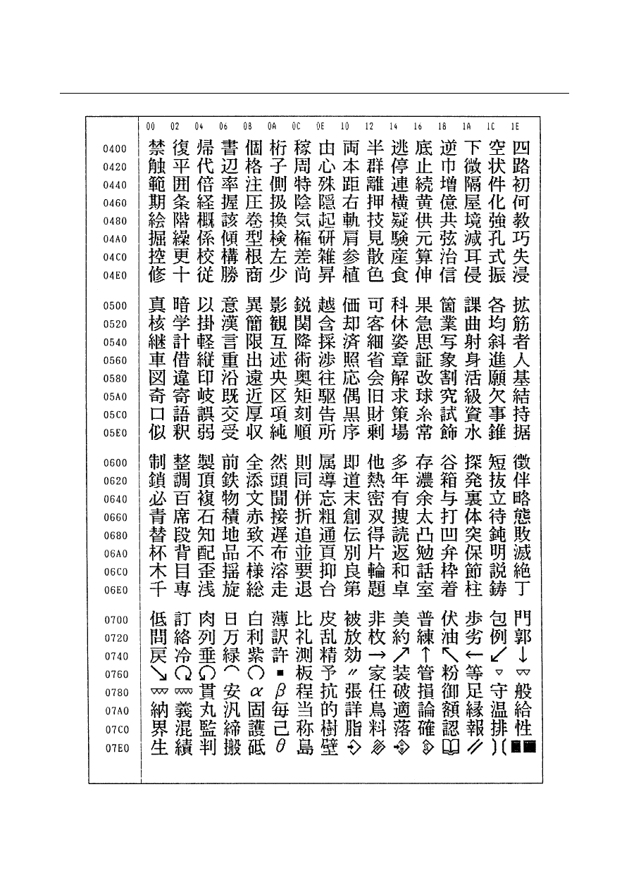
G. CHARACTER-TO-CODES 

CORRESPONDENCE 


B-63944EN/03

 APPENDIX 


- 2317 - 

G.CHARACTER-TO-CODES

CORRESPONDENCE TABLE


 APPENDIX 

B-63944EN/03


- 2318 - 

G. CHARACTER-TO-CODES 

CORRESPONDENCE 


B-63944EN/03

 APPENDIX 


- 2319 - 

G.CHARACTER-TO-CODES

CORRESPONDENCE TABLE


 APPENDIX 

B-63944EN/03


- 2320 - 

G. CHARACTER-TO-CODES 

CORRESPONDENCE 


B-63944EN/03

 APPENDIX 

H.ALARM LIST


- 2321 - 

ALARM LIST 

 
Appendix H, "ALARM LIST", consists of the following itemss: 
 
(1) Alarms on program and operation (PS alarm)...........................2322 
(2) Background edit alarms (BG alarm) .........................................2322 
(3) Communication alarms (SR alarm)...........................................2322 
(4) Parameter writing alarm (SW alarm) ........................................2361 
(5) Servo alarms (SV alarm) ...........................................................2361 
(6) Overtravel alarms (OT alarm) ...................................................2368 
(7) Memory file alarms (IO alarm) .................................................2369 
(8) Alarms requiring power to be turned off (PW alarm) ...............2369 
(9) Spindle alarms (SP alarm).........................................................2371 
(10) Alarm list (serial spindle)........................................................2374 
(11) Overheat alarms (OH alarm) ...................................................2383 
(12) Other alarms (DS alarm) .........................................................2384 
(13) Malfunction prevention function alarms (IE alarm)................2388 


H.ALARM LIST

 APPENDIX 

B-63944EN/03


- 2322 - 

(1) Alarms on program and operation (PS alarm) 
(2) Background edit alarms (BG alarm) 
(3) Communication alarms (SR alarm) 

 
Alarm numbers are common to all these alarm types. 
Depending on the state, an alarm is displayed as in the following 
examples: 
PS"alarm number"  Example:  PS0003 
BG"alarm number"


Example:  BG0085 

SR"alarm number"  Example:  SR0001 
 

Number Message 

Description 

0001 

TH ERROR 

A TH error was detected during reading from an input device. 
The read code that caused the TH error and how many 
statements it is from the block can be verified in the diagnostics 
screen. 

0002 

TV ERROR 

An error was detected during the single–block TV error. 
The TV check can be suppressed by setting TVC parameter No. 
0000#0 to “0”. 

0003 

TOO MANY DIGIT 

Data entered with more digits than permitted in the NC 
instruction word. 
The number of permissible digits varies according to the 
function and the word. 

0004 

INVALID BREAK POINT OF WORDS 

NC word(s) address + numerical value not in word format. This 
alarm is also generated when a custom macro does not contain 
a reserved word, or does not conform to the syntax. 

0005 

NO DATA AFTER ADDRESS 

NC word(s) address + numerical value not in word format. This 
alarm is also generated when a custom macro does not contain 
a reserved word, or does not conform to the syntax. 

0006 

ILLEGAL USE OF MINUS SIGN 

A minus sign (–) was specified at an NC instruction word or 
system variable where no minus signal may be specified. 

0007 

ILLEGAL USE OF DECIMAL POINT 

A decimal point (.) was specified at an address where no 
decimal point may be specified, or two decimal points were 
specified. 

0009 

IMPROPER NC-ADDRESS 

An illegal address was specified, or parameter 1020 is not set. 

0010 

IMPROPER G-CODE 

An unusable G code is specified. 

0011 

FEED ZERO ( COMMAND ) 

The cutting feedrate instructed by an F code has been set to 0. 
This alarm is also generated if the F code instructed for the S 
code is set extremely small in a rigid tapping instruction as the 
tool cannot cut at the programmed lead. 

0014 

CAN NOT COMMAND G95 

A synchronous feed is specified without the option for threading 
/ synchronous feed. Modify the program. 

0015 

TOO MANY SIMULTANEOUS AXES 

A move command was specified for more axes than can be 
controlled by simultaneous axis control. 
Either add on the simultaneous axis control extension option, or 
divide the number of programmed move axes into two blocks. 

0020 

OVER TOLERANCE OF RADIUS 

An arc was specified for which the difference in the radius at the 
start and end points exceeds the value set in parameter No. 
3410. Check arc center codes I, J and K in the program. 
The tool path when parameter No. 3410 is set to a large value is 
spiral. 

B-63944EN/03

 APPENDIX 

H.ALARM LIST


- 2323 - 

Number Message 

Description 

0021 

ILLEGAL PLANE SELECT 

The plane selection instructions G17 to G19 are in error. 
Reprogram so that same 3 basic parallel axes are not specified 
simultaneously. 
This alarm is also generated when an axis that should not be 
specified for plane machining is specified, for example, for 
circular interpolation or involute interpolation. 
To enable programming of 3 or more axes, the helical 
interpolation option must be added to each of the relevant axes.

0022 

R OR I,J,K COMMAND NOT FOUND 

The command for circular interpolation lacks arc radius R or 
coordinate I, J, or K of the distance between the start point to 
the center of the arc. 

0025 

CIRCLE CUT IN RAPID (F0) 

F0 (rapid traverse in inverse feed or feed specified by an F code 
with 1–digit number) was specified during circular interpolation 
(G02, G03) or involute interpolation (G02.2, G03.2). 

0027 

NO AXES COMMANDED IN G43/G44

No axis is specified in G43 and G44 blocks for the tool length 
offset type C. 
Offset is not canceled but another axis is offset for the tool 
length offset type C.   
Multiple axes were specified for the same block when the tool 
length compensation type is C. 

0028 

ILLEGAL PLANE SELECT 

The plane selection instructions G17 to G19 are in error. 
Reprogram so that same 3 basic parallel axes are not specified 
simultaneously. 
This alarm is also generated when an axis that should not be 
specified for plane machining is specified, for example, for 
circular interpolation or involute interpolation. 
To enable programming of 3 or more axes, the helical 
interpolation option must be added to each of the relevant axes.

0029 

ILLEGAL OFFSET VALUE 

Illegal offset No. 

0030 

ILLEGAL OFFSET NUMBER 

An illegal offset No. was specified. 
This alarm is also generated when the tool shape offset No. 
exceeds the maximum number of tool offset sets in the case of 
tool offset memory B. 

0031 

ILLEGAL P COMMAND IN G10 

The relevant data input or option could not be found for the L 
No. of G10. 
No data setting address such as P or R was specified. 
An address command not concerned with data setting was 
specified. An address varies with the L No. 
The sign or decimal point of the specified address is in error, or 
the specified address is out of range. 

0032 

ILLEGAL OFFSET VALUE IN G10 

In setting an offset amount by G10 or in writing an offset amount 
by system variables, the offset amount was excessive. 

0033 

NO INTERSECTION AT CUTTER 
COMPENSATION 

The intersection cannot be obtained by the intersection 
calculation in tool radius/tool nose radius compensation. Modify 
the program. 

0034 

NO CIRC ALLOWED IN STUP/EXT 
BLK 

In tool radius/tool nose radius compensation, a startup or 
cancellation is performed in the G02 or G03 mode. Modify the 
program. 


Content      ..     293      294      295      296     ..