FANUC Series 30i/300i/300is-MODEL A. Machining Center System. User's manual - page 293
 

  Index      Manuals     FANUC Series 30i/300i/300is-MODEL A. Machining Center System. User's manual (B-63944EN/03)


Search            copyright infringement  


Content      ..     291      292      293      294     ..


FANUC Series 30i/300i/300is-MODEL A. Machining Center System. User's manual - page 293


D.RANGE OF COMMAND VALUE

 APPENDIX 

B-63944EN/03


- 2300 - 

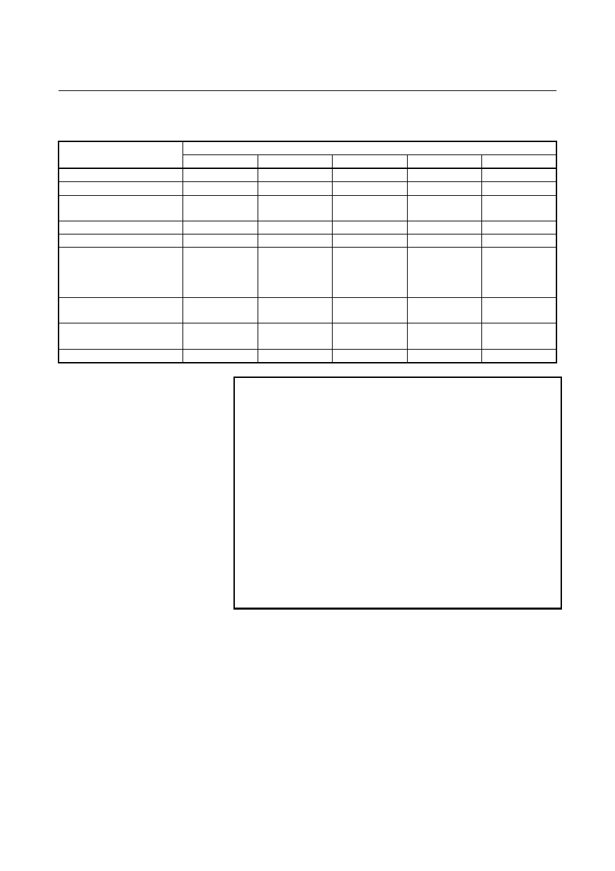
 - Rotary axis 


Increment system 


IS-A IS-B IS-C IS-D IS-E 

Least input increment (deg) 

0.01 

0.001 

0.0001 

0.00001 

0.000001 

Least command increment (deg)  0.01 

0.001 

0.0001 

0.00001 

0.000001 

Max. programmable dimension 
(deg) 

±

999,999.99 

±

999,999.999 

±

99,999.9999 

±

9,999.99999 

±

999.999999 

Max. rapid traverse (deg/min)

*1


999,000 999,000 100,000 10,000  1,000 

Feedrate range (deg/min)

*1


0.01 to 999,000 

0.001 to 999,000 

0.0001 to 100,000 0.00001 to 10,000  0.000001 to 1,000

Incremental feed (deg/step)   

0.01 
0.1 
1.0 
10.0 

0.001 
0.01 
0.1 
1.0 

0.0001 
0.001 
0.01 
0.1 

0.00001 
0.0001 
0.001 
0.01 

0.000001 
0.00001 
0.0001 
0.001 

Tool compensation amount 
(deg)

*2


0 to 

±

9,999.99 0 

to 

±

9,999.999 0 

to 

±

9,999.9999 0 

to 

±

9,999.99999 0 

to 

±

999.999999

Backlash compensation amount 
(pulses)

*3


0 to 

±

9,999 0 

to 

±

9,999 0 

to 

±

9,999 0 

to 

±

9,999 0 

to 

±

9,999 

Dwell (sec)

*4


0 to 999,999.99 

0 to 999,999.999 

0 to 99,999.9999 

0 to 9,999.99999 

0 to 999.999999 


NOTE 

*1  The feedrate range shown above are limitations 

depending on CNC interpolation capacity.    As a 
whole system, limitations depending on servo 
system must also be considered. 

*2  If the mode of input is switched between inch input 

and metric input, the maximum compensation value 
that can be set at inch input time is (maximum 
compensation value) 

×

 1/25.4.    If a value 

exceeding this value is specified at inch input time, 
the compensation value is not converted to a metric 
value correctly when the mode of input is switched 
to metric input. 

*3  The unit is the detection unit. 
*4  Depends on the increment system of the axis at in 

address X. 


B-63944EN/03

 APPENDIX 

E.NOMOGRAPHS


- 2301 - 

NOMOGRAPHS 

 
Appendix E, "NOMOGRAPHS", consists of the following sections: 
 
E.1  INCORRECT THREADED LENGTH...................................2302 
E.2  SIMPLE CALCULATION OF INCORRECT THREAD 

LENGTH.................................................................................2304 

E.3  TOOL PATH AT CORNER ...................................................2306 
E.4  RADIUS DIRECTION ERROR AT CIRCLE CUTTING .....2309 


E.NOMOGRAPHS

 APPENDIX 

B-63944EN/03


- 2302 - 

E.1 

INCORRECT THREADED LENGTH 

 
The leads of a thread are generally incorrect in 

δ

1

 and 

δ

2

, as shown in   

Fig. E.1 (a), due to automatic acceleration and deceleration. 
Thus distance allowances must be made to the extent of 

δ

1

 and 

δ

2

 in 

the program. 

δ

2

δ

1


Fig. E.1 (a)    Incorrect thread position 


Explanation 
  - How to determine 

δ

2


δ

2

=T

1

(mm ). . . . (1) 

V = 

1

60RL


T

1

  :  Time constant of servo system (sec) 

V  :  Threading speed (mm/sec) 
R  :  Spindle speed (min

-1

L  :  Thread feed (mm) 
Time constant T

1

 (sec) of the servo system: Usually 0.033 s. 


  - How to determine 

δ

1


δ

1

  = {t - T

1

 + T

1

exp( - 

t

T

1

 )} V

  . . . . . (2) 

a = exp( -

t

T

1

)

  . . . . . (3) 

T

1

  :  Time constant of servo system (sec) 

V  :  Threading speed (mm/sec) 
Time constant T

1

 (sec) of the servo system: Usually 0.033 s. 

 
The lead at the beginning of thread cutting is shorter than the specified 
lead L, and the allowable lead error is 

L. Then as follows. 

a=

L

L


When the value of “a” is determined, the time lapse until the thread 
accuracy is attained. The time “t” is substituted in (2) to determine 

δ

1

Constants V and T

1

 are determined in the same way as for 

δ

2

. Since 

the calculation of 

δ

1

 is rather complex, a nomography is provided on 

the following pages. 
 

B-63944EN/03

 APPENDIX 

E.NOMOGRAPHS


- 2303 - 

  - How to use nomograph 

First specify the class and the lead of a thread. The thread accuracy, a, 
will be obtained at (1), and depending on the time constant of cutting 
feed acceleration/ deceleration, the 

δ

1

 value when V = 10mm/s will be 

obtained at (2). Then, depending on the speed of thread cutting, 

δ

1

 for 

speed other than 10mm/s can be obtained at (3). 

(Note) See the graph in    reference later in the manual for an actual example.

V=40mm/sec

V=20mm/sec

(3)

  0

δ

1

a

L

L

(1)

(2)

δ

1

(V=10mm/sec)

T

1

T

2

Time constant of servo system


Fig. E.1 (b)    Nomograph 


NOTE 


The equations for 

δ

1

, and 

δ

2

 are for when the 

acceleration/ deceleration time constant for cutting 
feed is 0. 


E.NOMOGRAPHS

 APPENDIX 

B-63944EN/03


- 2304 - 

E.2 

SIMPLE CALCULATION OF INCORRECT THREAD 
LENGTH 


δ

2

δ

1


Fig. E.2 (a)    Incorrect threaded portion 


Explanation 
  - How to determine 

δ

2


a=

L

L

(mm)


R :  Spindle speed (min

-1

L  :  Thread lead (mm) 
* When time constant T

1

 of the servo system is 0.033 s. 


  - How to determine 

δ

1


δ

1

LR

1800*( - 1 - lna) 

(mm) 


=

δ

2

( - 1 - lna)

(mm) 

R :  Spindle speed (min

-1

L  :  Thread lead (mm) 
* When time constant T

1

 of the servo system is 0.033 s. 

Following a is a permited value of thread. 

a

-1-lna

0.005

4.298

0.01

0.015

0.02

3.605

3.200

2.912


Example 

R=350rpm 
L=1mm 
a=0.01 
then 

δ

2

 = 

350

×

1

1800  = 0.194

(mm)


δ

1

 = 

δ

2

×

3.605 = 0.701

(mm) 

B-63944EN/03

 APPENDIX 

E.NOMOGRAPHS


- 2305 - 

Reference 

V : Speed in threading

Servo time constant

50msec

V=10mm/sec
(  0.39in/sec)

V=20mm/sec
(  0.79in/sec)

V=30mm/sec
(  1.18in/sec)

V=40mm/sec
(  1.57in/sec)

V=2in/sec

V=1in/sec

δ

1

 (V=10mm/sec)

33msec

δ

1

8 (mm)

0.3 (in)

δ

1

6

4

2

0

0.2

0.1

0.007

0.010

0.015

0.020

0.025

Metric thread

JIS class 1
JIS class 2

Unified thread

3.3 3.0 2.5 2.0 1.5

1.2

1.0 0.9

0.7

0.

0.4

0.3 (mm) P  Lead

P  Lead

a= (

L

  L

5.0 4.0 3.5 3.0

2.5 2.0 1.75 1.5

1.25

1.0

0.9 0.8

0.75 (mm)

4 5

6 7 8 910 121314 161820

6

7 8 9 1012 14161820

Ridge/inch

Ridge/inch

)

        JIS 2A
        JIS 3A

 (Theoretical accuracy)


Fig. E.2 (b)    Nomograph for obtaining approach distance 

δ

1


E.NOMOGRAPHS

 APPENDIX 

B-63944EN/03


- 2306 - 

E.3 

TOOL PATH AT CORNER 

 
When servo system delay (by exponential acceleration/deceleration at 
cutting or caused by the positioning system when a servo motor is 
used) is accompanied by cornering, a slight deviation is produced 
between the tool path (tool center path) and the programmed path as 
shown in Fig. E.3 (a). 
Time constant T

1

 of the exponential acceleration/deceleration is fixed 

to 0. 

θ

V

1

V

2

Tool path

Programmed path


Fig. E.3 (a)    Slight deviation between the tool path and the programmed 

path 

 
This tool path is determined by the following parameters: 

 Feedrate 

(V

1

, V

2


Corner angle (

θ

  Exponential acceleration / deceleration time constant (T

1

) at 

cutting (T

1

 = 0)     


Presence or absence of buffer register. 

The above parameters are used to theoretically analyze the tool path 
and above tool path is drawn with    the parameter which is set as an 
example. 
When actually programming, the above items must be considered and 
programming must be performed carefully so that the shape of the 
workpiece is within the desired precision. 
In other words, when the shape of the workpiece is not within the 
theoretical precision, the commands of the next block must not be read 
until the specified feedrate becomes zero. The dwell function is then 
used to stop the machine for the appropriate period. 

B-63944EN/03

 APPENDIX 

E.NOMOGRAPHS


- 2307 - 

Explanation 
 - Analysis 

The tool path shown in Fig. E.3 (b) is analyzed based on the following 
conditions: 


Feedrate is constant at both blocks before and after cornering. 


The controller has a buffer register. (The error differs with the 
reading speed of the tape reader, number of characters of the next 
block, etc.) 

θ

V

V

X1

V

Y1

φ

2

V

Y2

V

X2

φ

2

V

Z

X

0


Fig. E.3 (b)    Example of tool path 


  - Description of conditions and symbols 

  V

X1

 = Vcos 

φ

1


  V

Y1

 = Vsin 

φ

  V

X2

 = Vcos 

φ

2


  V

Y2

 = Vsin 

φ

 
V  :  Feedrate at both blocks before and after cornering 
V

X1

 :  X-axis component of feedrate of preceding block 

V

Y1

 :  Y-axis component of feedrate of preceding block 

V

X2

 :  X-axis component of feedrate of following block 

V

Y2

 :  Y-axis component of feedrate of following block 

θ

 : 

Corner 

angle 

φ

1

  :  Angle formed by specified path direction of preceding block and 

X-axis 

φ

2

  :  Angle formed by specified path direction of following block and X-axis


Content      ..     291      292      293      294     ..