FANUC Series 30i/300i/300is-MODEL A. Machining Center System. User's manual - page 275
 

  Index      Manuals     FANUC Series 30i/300i/300is-MODEL A. Machining Center System. User's manual (B-63944EN/03)


Search            copyright infringement  


Content      ..     273      274      275      276     ..


FANUC Series 30i/300i/300is-MODEL A. Machining Center System. User's manual - page 275


A.PARAMETERS

 APPENDIX 

B-63944EN/03


- 2156 - 


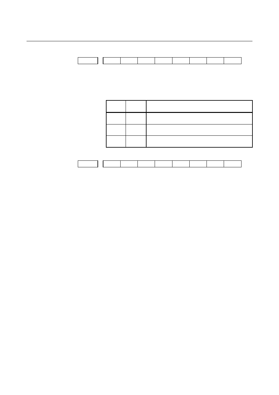
#7 #6 #5 #4 #3 #2 #1 #0 

7502 


LC2 

LC1 


[Input type]  Parameter input 


[Data type]  Bit path 


        # 4 

LC1


        # 5 

LC2


LC2 LC1 

End timing of servo learning function during 

high-speed cycle cutting retract function 

0 0 

Disables the servo learning function, after which 
retract operation starts. 

0 1 

Disables the servo learning function upon the 
completion of retract operation. 

1 0 

Disables the servo learning function upon the 
completion of a retract cycle. 


#7 #6 #5 #4 #3 #2 #1 #0 

7503 


HCT 


[Input type]  Parameter input 


[Data type]  Bit path 


        # 4 

HCT

  The variable number for starting storage of high-speed cycle 

machining distribution data is: 
0:  Specified by 1/10. 
1:  Specified by 1/100. 
 

B-63944EN/03

 APPENDIX 

A.PARAMETERS


- 2157 - 


#7 #6 #5 #4 #3 #2 #1 #0 

7505 


HUN 


[Input type]  Parameter input 


[Data type]  Bit axis 


NOTE 


When this parameter bit is set, the power must be 
turned off before operation is continued. 


        # 1 

HUN

  During high-speed cutting, the increment system of distribution data 

is: 
0: 1 

pulse. 

1: 10 

pulses. 


NOTE 


If data distributed at one time is longer than one 
word because of the least input increment and the 
maximum movement feedrate, this parameter is 
used. If bit parameter HUN is set to 1 for an axis, 
high-speed cycle machining data distributed to that 
axis is internally multiplied by 10 by the CNC and 
then input. Therefore, when using HUN for an axis, 
set a tenth of high-speed cycle machining data to 
be distributed to that axis. 


7510 


Number of controlled axes for high-speed cycle machining 


[Input type]  Parameter input 


[Data type]  Word path 

  [Valid data range]  1 to number of controlled axes 

Set the number of axes to be controlled when G05 is specified to 
perform high-speed cycle machining. 
 

7514 

  Retract direction and retract feedrate in high-speed cycle machining retract 

operation 


[Input type]  Parameter input 


[Data type]  Real axis 

  [Valid data range]  Refer to standard parameter setting table (C) 

This parameter sets a retract direction and retract feedrate along each 
axis in a high-speed cycle machining retract operation. The 
superimposed feedrate for each axis is specified, and the retract 
direction is specified with a sign. 
 

A.PARAMETERS

 APPENDIX 

B-63944EN/03


- 2158 - 

7515 


Number of retract operation distributions in a high-speed cycle machining 

retract operation 


[Input type]  Parameter input 


[Data type]  2-word path 

  [Valid data range]  0 to 99999999 

This parameter sets the number of retract operation distributions in a 
high-speed cycle machining retract operation. 
When the cycle currently being executed ends before the number of 
distributions specified in this parameter are performed, retract 
operation is terminated. When 0 is specified in this parameter, the 
number of retract operation distributions is assumed to be infinite. In 
this case, retract operation is performed until the cycle currently being 
executed ends. 


#7 #6 #5 #4 #3 #2 #1 #0 

7600 


PLZ 


[Input type]  Parameter input 


[Data type]  Bit path 


        # 7 

PLZ

  Reference position return based on a G28 command on the tool 

rotation axis for polygon turning is: 
0:  Performed in the same sequence as manual reference position 

return. 

1:  Performed by positioning using the rapid traverse rate. 
The synchronous axis returns to the reference position in the same 
sequence as the manual reference position return when no 
return-to-reference position is performed after the power is turned on. 
 

7610 


Control axis number of tool rotation axis for polygon turning 


NOTE 


When this parameter is set, the power must be 
turned off before operation is continued. 


[Input type]  Parameter input 


[Data type]  Byte path 

  [Valid data range]  1 to number of controlled axes 

This parameter sets the control axis number of a rotation tool axis 
used for polygon turning. 
However, when a G51.2 command is executed by setting 0 in this 
parameter, operation stops with the alarm (PS0314). 
 

B-63944EN/03

 APPENDIX 

A.PARAMETERS


- 2159 - 

7640 


Master axis in spindle-spindle polygon turning 


[Input type]  Parameter input 


[Data type]  Byte path 

  [Valid data range]  0 to Maximum number of controlled axes (Within a path) 

This parameter sets the master axis in spindle-spindle polygon turning. 
 

NOTE 

1  Spindle-spindle polygon turning is enabled only for serial spindles. 
2  When any one of parameter No. 7640 and No. 7641 is set to 0, polygon turning is 

performed using the first spindle (master axis) and the second spindle (polygon 
synchronous axis) in the path to which the parameter belongs. 

3  When a spindle other than the first serial spindle is used as a master axis, the 

multi-spindle control option is required to specify an S command for the master 
axis. 

4  When the PMC window function or G10 command is used to rewrite this parameter, 

rewrite this parameter before the block specifying the spindle-spindle polygon 
command G51.2. When the PMC window function is used to rewrite this parameter 
in the block immediately before G51.2, specify the rewriting of this parameter by 
using an M code (parameter No. 3411 and up) without buffering. 


7641 


Polygon synchronous axis in spindle-spindle polygon turning 


[Input type]  Parameter input 


[Data type]  Byte path 

  [Valid data range]  0 to Maximum number of controlled axes (Within a path) 

This parameter sets the polygon synchronous (slave) axis in 
spindle-spindle polygon turning. 
 

NOTE 

1  Spindle-spindle polygon turning is enabled only for serial spindles. 
2  When any one of parameter No. 7640 and No. 7641 is set to 0, polygon turning is 

performed using the first spindle (master axis) and the second spindle (polygon 
synchronous axis) in the path to which the parameter belongs. 

3  When a spindle other than the first serial spindle is used as a master axis, the 

multi-spindle control option is required to specify an S command for the master 
axis. 

4  When the PMC window function or G10 command is used to rewrite this parameter, 

rewrite this parameter before the block specifying the spindle-spindle polygon 
command G51.2. When the PMC window function is used to rewrite this parameter 
in the block immediately before G51.2, specify the rewriting of this parameter by 
using an M code (parameter No. 3411 and up) without buffering. 


A.PARAMETERS

 APPENDIX 

B-63944EN/03


- 2160 - 

7642 

  Master axis in spindle-spindle polygon turning (spindle number common to 

the system) 


[Input type]  Parameter input 


[Data type]  Byte path 

  [Valid data range]  0 to Maximum number of controlled axes (Common to the system) 

This parameter sets the master axis in spindle-spindle polygon turning. 
 

NOTE 

1  Spindle-spindle polygon turning is enabled only for serial spindles. 
2  This parameter is invalid if either parameter No. 7642 or No.7643 is set to 0. In this 

case, the settings of parameter No. 7640 and No.7641 are valid. 

3  When a spindle other than the first serial spindle is used as a master axis, the 

multi-spindle control option is required to specify an S command for the master 
axis. 

4  When the PMC window function or G10 command is used to rewrite this parameter, 

rewrite this parameter before the block specifying the spindle-spindle polygon 
command G51.2. When the PMC window function is used to rewrite this parameter 
in the block immediately before G51.2, specify the rewriting of this parameter by 
using an M code (parameter No. 3411 and up) without buffering. 

5  A spindle number common to the system is to be set in this parameter. When using 

this parameter, set 0 in parameter No. 7640 and No. 7641. 


7643 


Polygon synchronous axis in spindle-spindle polygon turning (spindle 

number common to the system) 


[Input type]  Parameter input 


[Data type]  Byte path 

  [Valid data range]  0 to Maximum number of controlled axes (Common to the system) 

This parameter sets the polygon synchronous (slave) axis in 
spindle-spindle polygon turning. 
 

NOTE 

1  Spindle-spindle polygon turning is enabled only for serial spindles. 
2  This parameter is invalid if either parameter No. 7642 or No.7643 is set to 0. In this 

case, the settings of parameter No. 7640 and No.7641 are valid. 

3  When a spindle other than the first serial spindle is used as a master axis, the 

multi-spindle control option is required to specify an S command for the master 
axis. 

4  When the PMC window function or G10 command is used to rewrite this parameter, 

rewrite this parameter before the block specifying the spindle-spindle polygon 
command G51.2. When the PMC window function is used to rewrite this parameter 
in the block immediately before G51.2, specify the rewriting of this parameter by 
using an M code (parameter No. 3411 and up) without buffering. 

5  A spindle number common to the system is to be set in this parameter. When using 

this parameter, set 0 in parameter No. 7640 and No. 7641. 


B-63944EN/03

 APPENDIX 

A.PARAMETERS


- 2161 - 


#7 #6 #5 #4 #3 #2 #1 #0 

7700 


HDR 


HBR 


[Input type]  Parameter input 


[Data type]  Bit path 


        # 0 

HBR

  When the electronic gear box (EGB) function is used, performing a 

reset: 
0:  Cancels the synchronous mode (G81 or G81.5). 
1:  Does not cancel the synchronous mode. The mode is canceled 

only by the G80 or G80.5 command. 


        # 2 

HDR

  Direction of helical gear compensation (usually, set 1.) 


  (Example) To cut a left-twisted herical gear when the direction of 

rotation about the C-axis is the negative (-) direction: 
0:  Set a negative (-) value in P. 
1:  Set a positive (+) value in P. 
 

When HDR = 1 

+C

C : +, Z : +, P : + 

Compensation direction:+

(a) 

-

Z


+Z

+C

C : +, Z : +, P : - 

Compensation direction:-

(b)

+C 

C : +, Z : -, P : + 

Compensation direction:-


(c)

+C

C : +, Z : -, P : - 

Compensation direction:+

(d) 

-

Z


+

Z


C : -, Z : +, P : + 

C : Compensation direction:-

(e) 

-

C

C : -, Z : +, P : - 

Compensation direction:+

(f) 

-

C


C : -, Z : -, P : + 

Compensation direction:+


(g) 

-

C


C : -, Z : -, P : - 

Compensation direction:-

(h) 

-

C


When HDR = 0 ((a), (b), (c), and (d) are the same as when HDR = 1)


-Z 

+

Z


C : -, Z : +, P : + 

Compensation direction:+

(e) 

-

C

C : -, Z : +, P : - 

Compensation direction:-

(f) 

-

C

C : -, Z : -, P : + 

Compensation direction:-


(g) 

-

C


C : -, Z : -, P : - 

Compensation direction:+

(h) 

-

C


A.PARAMETERS

 APPENDIX 

B-63944EN/03


- 2162 - 


#7 #6 #5 #4 #3 #2 #1 #0 

7701 


LZR 


[Input type]  Parameter input 


[Data type]  Bit path 


        # 3 

LZR

  When L (number of hob threads) = 0 is specified at the start of EGB 

synchronization (G81): 
0:  Synchronization is started, assuming that L = 1 is specified. 
1:  Synchronization is not started, assuming that L = 0 is specified. 

However, helical gear compensation is performed. 


#7 #6 #5 #4 #3 #2 #1 #0 

7702 


PHD 

PHS 


ART 


TDP 


[Input type]  Parameter input 


[Data type]  Bit path 


        # 0 

TDP

  The specifiable number of teeth, T, of the electronic gear box (G81) 

is: 
0:  1 to 1000 
1:  0.1 to 100 (1/10 of a specified value) 
 

NOTE 


In either case, a value from 1 to 1000 can be 
specified. 


        # 3 

ART

  The retract function executed when an alarm is issued is: 

0: Disabled. 
1: Enabled. 
When an alarm is issued, a retract operation is performed with a set 
feedrate and travel distance (parameter Nos. 7740 and 7741). 
 

NOTE 


If a servo alarm is issued for other than the axis 
along which a retract operation is performed, the 
servo activating current is maintained until the 
retract operation is completed. 


        # 6 

PHS

  When the G81/G80 block contains no R command: 

0:  Acceleration/deceleration is not performed at the start or 

cancellation of EGB synchronization. 

1:  Acceleration/deceleration is performed at the start or cancellation 

of EGB synchronization. After acceleration at the start of 
synchronization, phase synchronization is automatically 
performed. 


        # 7 

PHD

  The direction of movement for automatic phase synchronization is: 

0: Positive 

(+). 

1: Negative 

(-). 


B-63944EN/03

 APPENDIX 

A.PARAMETERS


- 2163 - 


#7 #6 #5 #4 #3 #2 #1 #0 

7703 


ARO 

ARE 

ERV 


[Input type]  Parameter input 


[Data type]  Bit path 


        # 0 

ERV

  During EGB synchronization (G81), feed per revolution is performed 

for: 
0: Feedback 

pulses. 

1:  Pulses converted to the speed for the workpiece axis. 
 

        # 1 

ARE

  The retract function executed when an alarm is issued retracts the tool 

during: 
0:  EGB synchronization or automatic operation (automatic 

operation signal OP = 1). 

1: EGB 

synchronization. 


        # 2 

ARO

  The retract function executed when an alarm is issued retracts the tool 

during: 
0: EGB 

synchronization. 

1:  EGB synchronization and automatic operation (automatic 

operation signal OP = 1). 


NOTE 


This parameter is valid when bit 1 (ARE) of 
parameter No. 7703 is set to 1. 

 
The following table lists the parameter settings and corresponding 
operation. 
 

ARE ARO 

Operation 

During EGB synchronization 

During EGB synchronization and automatic operation

0 0 
0 1 

During EGB synchronization or automatic operation 


NOTE 

1  Parameters ARE and ARO are valid when bit 3 

(ART) of parameter No. 7702 is set to 1 (when the 
retract function executed when an alarm is 
issued ). 

2  This parameter is valid when bit 1 (ARE) of 

parameter No. 7703 is set to 1. 


Content      ..     273      274      275      276     ..