FANUC Series 30i/300i/300is-MODEL A. Machining Center System. User's manual - page 273
 

  Index      Manuals     FANUC Series 30i/300i/300is-MODEL A. Machining Center System. User's manual (B-63944EN/03)


Search            copyright infringement  


Content      ..     271      272      273      274     ..


FANUC Series 30i/300i/300is-MODEL A. Machining Center System. User's manual - page 273


A.PARAMETERS

 APPENDIX 

B-63944EN/03


- 2140 - 

#1 TCO


#2 E17


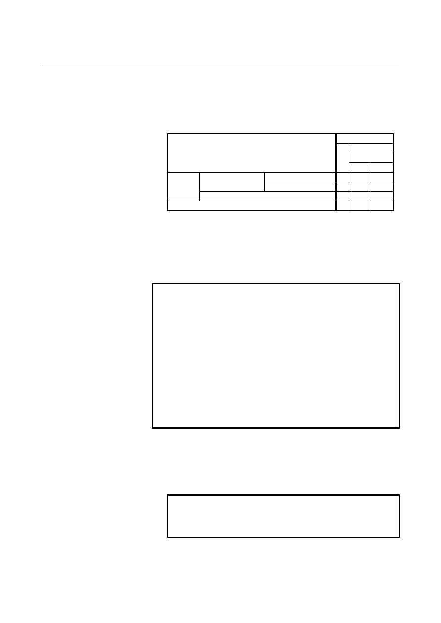
Specifies whether to allow the FOCAS2 or PMC window function to 
write tool information of a group being used or a group to be used 
next during automatic operation (the OP signal is set to "1"). 


6802#1(TCO) 

6802#2(E17)

Condition 

1 0 

Tool being used 

× 


Group being used or 

to be used next 

Tool not being used 

× 


During 

automatic 

operation Group neither being used nor to be used next 


Not during automatic operation 


:  Tool information can be written from FOCAS2 and PMC 

window. 

×:  Tool information cannot be written from FOCAS2 and PMC 

window. 


When an attempt is made to write tool information from PMC 
window, completion code 13 (REJECT ALARM) is returned. 

:  Tool information cannot be cleared. 


NOTE 

When tool information of a tool being used (marked 
with "@") in the group being used or to be used next or 
tool information of the most recently used tool (marked 
with "@") in a group that is neither the group being 
used nor the group to be used next is cleared, the life 
counter is reset to 0. 
It is possible to modify tool information of a tool in the 
group to be used next. However, because tool 
selection is already completed, the selected tool does 
not change even when the tool information is modified. 


This parameter has no influence on modifications to tool 
information by edit operations from the tool life 
management screen. 


        # 3 

GRP

  Management data of tool life arrival notice signal TLCHB is: 

0:  Managed using the remaining life value set in parameter No. 

6844 and 6845. 

1:  Managed using the remaining life value set in tool life 

management data. 


NOTE 


When the tool life arrival notice signal function is 
used, bit 4 (LFB) of parameter No. 6805 must be set 
to 1 to enable the tool life management B function. 


B-63944EN/03

 APPENDIX 

A.PARAMETERS


- 2141 - 

        # 4 

ARL

  Tool life arrival notice signal TLCHB of tool life management is: 

0:  Output for each tool. 
1:  Output for the last tool of a group. 
This parameter is valid only when bit 3 (GRP) of parameter No. 6802 
is set to 1. 
 

        # 5 

TGN

  In the tool life management function, the optional group number 

function is: 
0: Not 

used. 

1: Used. 
 

NOTE 

When the optional group number function is used, 
bit 4 (LFB) of parameter No. 6805 must be set to 1 
to enable the tool life management B function. 


In lathe systems, the optional group number function 
can be used if the tool change type is the ATC type 
(bit 3 (TCT) of parameter No. 5040 = 1). 


        # 6 

TSK

  If the count type in tool life management is the duration type, then 

when the last tool of a group is skipped by a signal: 
0:  The count value for the last tool equals the life value. 
1:  The count value for the last tool remains unchanged. 
 

        # 7 

RMT

  Tool life arrival notice signal TLCHB is turned on and off as follows: 

0:  The signal is turned on if the remaining life value (the life value 

minus the life counter value) is smaller than or equal to the 
remaining life setting. The signal is turned off if the remaining 
life value (the life value minus the life counter value) is greater 
than the remaining life setting. 

1:  The signal is turned on if the remaining life value (the life value 

minus the life counter value) is equal to the remaining life setting. 
The signal is turned off if the remaining life value (the life value 
minus the life counter value) is not equal to the remaining life 
setting. 


NOTE 


When using the life count override feature, set bit 7 
(RMT) of parameter No. 6802 to 0. When the life 
count is specified by duration, the unit used for 
determining the result of comparison between the 
remaining life and the remaining life setting varies 
depending on the life count interval (bit 0 (FCO) of 
parameter No. 6805). If the life is counted every 
second, the comparison is made in units of 1 minute; 
if the life is counted every 0.1 second, the 
comparison is made in units of 0.1 minute. 


A.PARAMETERS

 APPENDIX 

B-63944EN/03


- 2142 - 


#7 #6 #5 #4 #3 #2 #1 #0 

6804 


LFI 


ETE 

TCI 


[Input type]  Parameter input 


[Data type]  Bit path 


        # 1 

TCI

  During automatic operation (the OP signal is "1"), editing of tool life 

data is: 
0: Disabled. 
1: Enabled. 
 

NOTE 


When this parameter is set to 1, tool life data can be 
edited even during automatic operation (the OP 
signal is "1"). If the target group for editing is the 
group being used or the group to be used next, 
however, only presetting of the life counter is 
permitted, and other data cannot be modified. 


        # 2 

ETE

  In the tool life management screen, the mark of the tool at the life was 

expired of the final tool in the group : 
0:  depends on setting parameter EMD (No.6801#3). 
1:  is "*" mark. 
If bit 2 (ETE) of parameter No. 6804 is set to 1, when the life counter 
of the final tool in the group becomes equal to the life value, display 
mark "*" in the final tool of the tool life management screen.   
When tool change signal TLCH<Fn064.0> is "1", the state of the life 
was expired of the tool can be read by reading tool information on the 
final tool in FOCAS2 or the PMC window. 
 

        # 6 

LFI

  In tool life management, counting of the life of a selected tool is: 

0: Enabled. 
1:  Enabled or disabled according to the status of tool life counting 

disable signal LFCIV<G048.2>. 


B-63944EN/03

 APPENDIX 

A.PARAMETERS


- 2143 - 


#7 #6 #5 #4 #3 #2 #1 #0 

6805  TAD  TRU  TRS  LFB 


FGL  FCO 


[Input type]  Parameter input 


[Data type]  Bit path 


        # 0 

FCO

  If the life count type is the duration specification type, the life is 

counted as follows: 
0: Every 

second. 

1:  Every 0.1 second. 
According to the setting of this parameter, the increment system of life 
values and tool life counter values displayed on the tool life 
management screen is set as follows: 
 

Parameter FCO 

  0 

Increment system for display and setting of life 
values and life counter values 

 1-minute 

increments 

0.1-minute 

increments


NOTE 


After changing the setting of this parameter, set data 
again by using G10L3;(registration after deletion of 
data of all groups). 


        # 1 

FGL

  If the life count type is the duration specification type, life data 

registered by G10 is: 
0:  In one-minute increments. 
1:  In 0.1-second increments. 
 

        # 4 

LFB

  The tool life management B function is: 

0: Disabled. 
1: Enabled. 
When the tool life management B function is enabled, the following 
functions can be used: 
<1> Tool life value extension (count specification: 99999999 times, 

duration specification: 100000 minutes) 

<2>  Optional group number function 
<3>  Tool life arrival notice function 
In lathe systems, if the tool change type is the ATC type (bit 3 (TCT) 
of parameter No. 5040 = 1), the optional group number function can 
be used. 
 

A.PARAMETERS

 APPENDIX 

B-63944EN/03


- 2144 - 

        # 5 

TRS

  Tool change reset signal TLRST is valid when reset signal RST is not 

"1" and: 
0:  The reset state (automatic operation signal OP is "0") is 

observed. 

1:  The reset state (automatic operation signal OP is "0"), automatic 

operation stop state (The STL and SPL signals are "0" and the 
OP signal is "1"), or the automatic operation pause state (the STL 
signal is "0" and the SPL signal is "1") is observed. The TLRST 
signal, however, is invalid when the automatic operation stop 
state, automatic operation pause state, and automatic operation 
start state (the STL signal is "1") is observed during execution of 
a data setting command (G10L3). 


        # 6 

TRU

  When the life count type is the duration specification type, and the life 

is counted every second (bit 0 (FCO) of parameter No. 6805 is set to 
0): 
0:  Cutting time less than one second is discarded and is not counted. 
1:  Cutting time less than one second is rounded up and is counted as 

one second. 


NOTE 


If the life is counted every 0.1 second (bit 0 (FCO) of 
parameter No. 6805 is set to 1), cutting time less 
than 0.1 second is always rounded up and is counted 
as 0.1 second. 


        # 7 

TAD

  With tool change type D (bit 7 (M6E) of parameter No. 6801 is set to 

1), when a block specifying M06 contains no T command: 
0:  An alarm PS0153 is issued. 
1:  No alarm is issued. 
 

6810 


Tool life management ignore number 


[Input type]  Parameter input 


[Data type]  2-word path 

  [Valid data range]  0 to 99999999 

This parameter sets the tool life management ignore number. 
When the value specified in a T code exceeds the value set in this 
parameter, the value obtained by subtracting the parameter-set value 
from the T code value is assumed to be the tool group number for tool 
life management. 
 

B-63944EN/03

 APPENDIX 

A.PARAMETERS


- 2145 - 

6811 


Tool life count restart M code 


[Input type]  Parameter input 


[Data type]  Byte path 

  [Valid data range]  0 to 127 (except 01, 02, 30, 98, and 99) 

When 0 is specified, it is ignored. 
When the life is specified by count, the tool change signal (TLCH) is 
output if the life of at least one tool group has expired when the tool 
life count restart M code is issued. 
The T code (tool life management group command) specified after the 
tool life count restart M code selects a tool whose life has not expired 
from a specified group, and the next M06 command increments the 
tool life counter by one. 
When the life is specified by duration, specifying the tool life count 
restart M code causes nothing. When 0 is set in this parameter, the tool 
life count restart M code is invalid. When the data of M code exceeds 
127 values, set 0 in parameter No.6811, and set the value of M code in 
parameter No.13221. The data range of parameter No.13221 is from 0 
to 255. 
 

NOTE 


The use of this parameter varies depending on 
whether the tool management function or tool life 
management function is used. 


6813 


Maximum number of groups in tool life management 


NOTE 


After this parameter has been set, the power must be 
turned off then back on for the setting to become 
effective. 


[Input type]  Parameter input 


[Data type]  Word path 


[Unit of data]  Group 

  [Valid data range]  0, 8, 16 to 256 

This parameter sets the maximum number of groups to be used for 
each path. As the maximum number of groups, set a multiple of eight. 
When the tool life management function is not used, 0 must be set. Set 
this parameter so that the total number of groups in all paths does not 
exceed the total number of groups in the entire system (256 groups). 
 

NOTE 


When the power is turned on, all tool life 
management file data is initialized. So, tool life 
management data must be set for all paths that use 
tool life management. 


A.PARAMETERS

 APPENDIX 

B-63944EN/03


- 2146 - 

6844 


Remaining tool life (use count) 


[Input type]  Parameter input 


[Data type]  Word path 

  [Valid data range]  0 to 9999 

This parameter sets a remaining tool life (use count) used to output the 
tool life arrival notice signal when the tool life is specified by use 
count. If a value greater than the tool life value or 0 is set in this 
parameter, the tool life arrival notice signal is not output. 
 

6845 


Remaining tool life (use duration) 


[Input type]  Parameter input 


[Data type]  2-word path 


[Unit of data]  min 

  [Valid data range]  Not greater than the tool life value 

This parameter sets the remaining tool life (use duration) used to 
output the tool life arrival notice signal when the tool life is specified 
by use duration. If a value greater than the tool life value or 0 is 
specified in this parameter, the tool life arrival notice signal is not 
output. 
 

NOTE 


When the life is counted every 0.1 second (bit 0 
(FCO) of parameter No. 6805 = 1), the parameter 
value is in 0.1-minute increments. 


6930 

  Maximum value of the operating range of the 1-st position switch (PSW101)


6931 

  Maximum value of the operating range of the 2-nd position switch (PSW102)

to 


  to 

6945 

  Maximum value of the operating range of the 16-th position switch (PSW116)


[Input type]  Parameter input 


[Data type]  Real path 


[Unit of data]  mm, inch, degree (machine unit) 


[Minimum unit of data]  Depend on the increment system of the reference axis 

 [Valid data range]  9 digit of minimum unit of data (refer to standard parameter setting 

table (A)) 
(When the increment system is IS-B, -999999.999 to +999999.999) 
Set the maximum value of the operating range of the first to sixteenth 
position switches. 
 

NOTE 

1  For a diameter-specified axis, use radius values to 

specify the parameters used to set the maximum 
and minimum values of an operating range. 

2  The position switch function is enabled upon 

completion of reference position return. 


B-63944EN/03

 APPENDIX 

A.PARAMETERS


- 2147 - 

6950 


Minimum value of the operating range of the 1-st position switch (PSW201)


6951 

  Minimum value of the operating range of the 2-nd position switch (PSW202)

to  


to 

6965 

  Minimum value of the operating range of the 16-th position switch (PSW216)


[Input type]  Parameter input 


[Data type]  Real path 


[Unit of data]  mm, inch, degree (machine unit) 


[Minimum unit of data]  Depend on the increment system of the reference axis 

 [Valid data range]  9 digit of minimum unit of data (refer to standard parameter setting 

table (A)) 
(When the increment system is IS-B, -999999.999 to +999999.999) 
Set the minimum value of the operating range of the first to sixteenth 
position switches. 
 

NOTE 

1  For a diameter-specified axis, use radius values to 

specify the parameters used to set the maximum 
and minimum values of an operating range. 

2  The position switch function is enabled upon 

completion of reference position return. 


#7 #6 #5 #4 #3 #2 #1 #0 

7001 


JST 


[Input type]  Parameter input 


[Data type]  Bit path 


    # 2 

JST

  In manual numerical specification, the STL signal indicating that 

automatic operation is being started is: 
0: Not 

output. 

1: Output. 


#7 #6 #5 #4 #3 #2 #1 #0 

7002 


JBF 

JTF 

JSF 

JMF 


[Input type]  Parameter input 


[Data type]  Bit path 


    # 0 

JMF

  In manual numerical specification, M function specification is: 

0: Allowed. 
1: Not 

allowed. 


    # 1 

JSF

  In manual numerical specification, S function specification is: 

0: Allowed. 
1: Not 

allowed. 


Content      ..     271      272      273      274     ..