FANUC Series 30i/300i/300is-MODEL A. Machining Center System. User's manual - page 271
 

  Index      Manuals     FANUC Series 30i/300i/300is-MODEL A. Machining Center System. User's manual (B-63944EN/03)


Search            copyright infringement  


Content      ..     269      270      271      272     ..


FANUC Series 30i/300i/300is-MODEL A. Machining Center System. User's manual - page 271


A.PARAMETERS

 APPENDIX 

B-63944EN/03


- 2124 - 


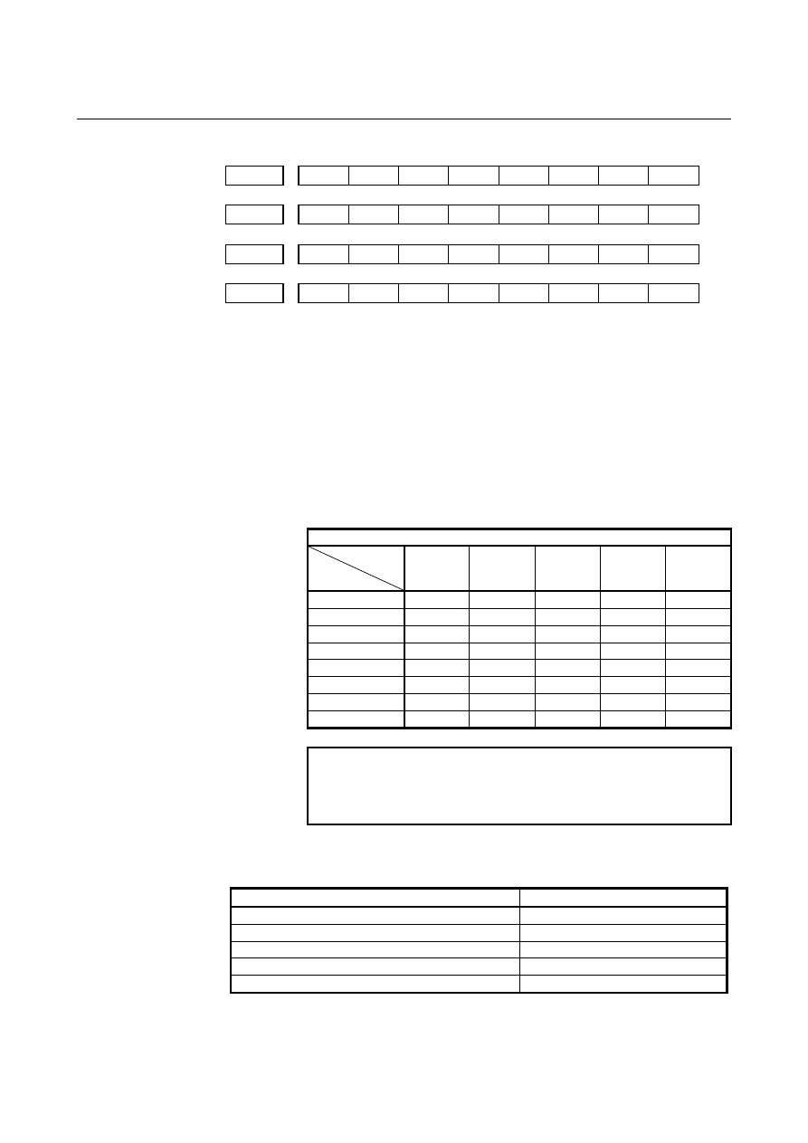
#7 #6 #5 #4 #3 #2 #1 #0 

6203 


2S8 2S7 2S6 2S5 2S4 2S3 2S2 2S1 


#7 #6 #5 #4 #3 #2 #1 #0 

6204 


3S8 3S7 3S6 3S5 3S4 3S3 3S2 3S1 


#7 #6 #5 #4 #3 #2 #1 #0 

6205 


4S8 4S7 4S6 4S5 4S4 4S3 4S2 4S1 


#7 #6 #5 #4 #3 #2 #1 #0 

6206  

DS8 DS7 DS6 DS5 DS4 DS3 DS2 DS1 


[Input type]  Parameter input 


[Data type]  Bit path 


         1S1to1S8, 2S1to2S8, 3S1to3S8, 4S1to4S8, DS1toDS8 

Specify which skip signal is enabled when the skip command (G31, or 
G31P1 to G31P4) and the dwell command (G04, G04Q1 to G04Q4) 
are issued with the multi-step skip function. 
The following table shows the correspondence between the bits, input 
signals, and commands. 
The setting of the bits have the following meaning : 
0:  The skip signal corresponding to a bit is invalid. 
1:  The skip signal corresponding to a bit is enabled. 

Multi-step skip function 

Command

Input  
signal 

G31 

G31P1 

G04Q1 


G31P2 

G04Q2 


G31P3 

G04Q3 


G31P4 

G04Q4 


G04 


SKIP/HDI0 1S1 2S1 3S1 4S1 DS1 

SKIP2/HDI1 1S2 2S2 3S2 4S2 DS2 
SKIP3/HDI2 1S3 2S3 3S3 4S3 DS3 
SKIP4/HDI3 1S4 2S4 3S4 4S4 DS4 
SKIP5/HDI4 1S5 2S5 3S5 4S5 DS5 
SKIP6/HDI5 1S6 2S6 3S6 4S6 DS6 
SKIP7/HDI6 1S7 2S7 3S7 4S7 DS7 
SKIP8/HDI7 1S8 2S8 3S8 4S8 DS8 


NOTE 


HDI0 to HDI7 are high-speed skip signals. Do not 
specify the same signal simultaneously for different 
paths. 

When bit 0 (GSK) of parameter No. 6200 is set to 1, commands to be 
skipped can be selected by setting the following parameter: 


Commands skipped by SKIPP signal <G006#6> 

Parameter Command 

skipped 

When bit 0 (1S1) of parameter No. 6202 is set to 1

G31P1,G04Q1 

When bit 0 (2S1) of parameter No. 6203 is set to 1

G31P2,G04Q2 

When bit 0 (3S1) of parameter No. 6204 is set to 1

G31P3,G04Q3 

When bit 0 (4S1) of parameter No. 6205 is set to 1

G31P4,G04Q4 

When bit 6 (DS1) of parameter No. 6206 is set to 1

G04,G04Q1,G04Q2,G04Q3,G04Q4


B-63944EN/03

 APPENDIX 

A.PARAMETERS


- 2125 - 


#7 #6 #5 #4 #3 #2 #1 #0 

6207 


SFN 

SFP 


[Input type]  Parameter input 


[Data type]  Bit path 


        # 1 

SFP

  The feedrate used when the skip function (G31) is being executed is: 

0:  Feedrate of a programmed F code. 
1:  Feedrate set in parameter No. 6281. 
 

NOTE 


For the multi-stage skip function and high-speed 
skip, see the description of bit 2 (SFN ) of 
parameter No. 6207. 


        # 2 

SFN

  The feedrate used when the skip function based on high-speed skip 

signals (with bit 1 (HSS) of parameter No. 6200 set to 1) or the 
multi-skip function is being executed is: 
0:  Feedrate of a programmed F code. 
1:  Feedrate set in a parameter from parameter No. 6282 to No. 

6285. 


NOTE 


For not the multistage skip function, but the skip 
function using no high-speed skip signals (when bit 
4 (HSS) of parameter No. 6200 is set to 0), see the 
description of bit 1 (SFP) of parameter No. 6207. 


#7 #6 #5 #4 #3 #2 #1 #0 

6208 


9S8 9S7 9S6 9S5 9S4 9S3 9S2 9S1 


[Input type]  Parameter input 


[Data type]  Bit path 


9S1 to 9S8

  Specify which high-speed skip signal is enabled for the continuous 

high-speed skip command G31P90 or the EGB skip command G31.8.


The settings of each bit have the following meaning: 
0:  The high-speed skip signal corresponding to the bit is disabled. 
1:    The high-speed skip signal corresponding to the bit is enabled. 
The bits correspond to signals as follows: 

Parameter 

High-speed skip 

signal 

Parameter 

High-speed skip 

signal 

9S1 HDI0 9S5 HDI4 
9S2 HDI1 9S6 HDI5 
9S3 HDI2 9S7 HDI6 
9S4 HDI3 9S8 HDI7 


A.PARAMETERS

 APPENDIX 

B-63944EN/03


- 2126 - 

6220 


Period during which skip signal input is ignored for the continuous 

high-speed skip function and EGB axis skip function 


[Input type]  Parameter input 


[Data type]  Byte path 


[Unit of data]  8msec 

  [Valid data range]  3 to 127(

×

 8msec) 

 
This parameter specifies the period from when a skip signal is input to 
when the next skip signal can be input for the continuous high-speed 
skip function and EGB axis skip function. This parameter is used to 
ignore chattering in skip signals. 
If a value that falls outside the valid range is specified, the setting is 
assumed to be 24 msec. 


Signal ignoring period (parameter No. 6220) 

Skip signal 

This signal is ignored. 


When high-speed skip signals are used and bit 5 (CSE) of parameter 
No. 6201 is set to 1, signals are handled as follows:


Signal ignoring period (parameter No. 6220) 

High-speed skip 
signals 

These signals 
are ignored. 


6221 


Torque limit dead zone time for a torque limit skip command 


[Input type]  Parameter input 


[Data type]  2-word axis 


[Unit of data]  msec 

  [Valid data range]  0 to 65535 

The torque limit skip arrival signal is ignored for a set period of time. 
If G31P98 is specified, skip operation is not performed for a set period 
of time after the torque limit skip arrival signal is set to 1. 
If G31P99 is specified, skip operation is not performed for a set period 
of time after the torque limit skip arrival signal is set to 1. 
However, if a skip signal is input, skip operation is performed, 
regardless of the period of time set in this parameter. 
 

B-63944EN/03

 APPENDIX 

A.PARAMETERS


- 2127 - 

6254  

ε

 value on the X axis during automatic tool compensation (T series) 


ε

 value during automatic tool length measurement (M series) (for the XAE1 

and GAE1 signals) 


6255  

ε

 value on the Z axis during automatic tool compensation (T series) 


ε

 value during automatic tool length measurement (M series) (for the XAE2 

and GAE2 signals) 


[Input type]  Parameter input 


[Data type]  2-word path 


[Unit of data]  mm, inch, deg (machine unit) 


[Minimum unit of data]  Depend on the increment system of the applied axis 

 [Valid data range]  9 digit of minimum unit of data (refer to standard parameter setting 

table (A))   
(When the increment system is IS-B, -999999.999 to +999999.999) 
These parameters set the relevant 

ε

 value during automatic tool 

compensation (T series) or automatic tool length measurement (M 
series). 
 

NOTE 

1  For the M series, when the setting of 

parameter No. 6252 or 6253 is 0, the setting 
of parameter No. 6251 is used. 

2  Set a radius value regardless of whether 

diameter or radius programming is specified. 


6281 


Feedrate for the skip function (G31) 


[Input type]  Parameter input 


[Data type]  Real path 


[Unit of data]  mm/min, inch/min, degree/min (machine unit) 


[Minimum unit of data]  Depend on the increment system of the reference axis 

  [Valid data range]  Refer to the standard parameter setting table (C) 

(When the increment system is IS-B, 0.0 to +999000.0) 
This parameter sets a feedrate for the skip function (G31). This 
parameter is valid when bit 1 (SFP) of parameter No. 6207 is set to 1. 
 

NOTE 


For the multi-stage skip function and high-speed 
skip, see the description of parameter No. 6282 to 
No. 6285. 


A.PARAMETERS

 APPENDIX 

B-63944EN/03


- 2128 - 

6282 


Feedrate for the skip function (G31, G31 P1) 


6283 


Feedrate for the skip function (G31 P2) 


6284 


Feedrate for the skip function (G31 P3) 


6285 


Feedrate for the skip function (G31 P4) 


[Input type]  Parameter input 


[Data type]  Real path 


[Unit of data]  mm/min, inch/min, degree/min (machine unit) 


[Minimum unit of data]  Depend on the increment system of the reference axis 

  [Valid data range]  Refer to the standard parameter setting table (C) 

(When the increment system is IS-B, 0.0 to +999000.0) 
Each of these parameters sets a feedrate for each skip function G code. 
These parameters are valid when bit 2 (SFN) of parameter No. 6207 is 
set to 1. 
 

6287 


Positional deviation limit in torque limit skip 


[Input type]  Parameter input 


[Data type]  2-word axis 


[Unit of data]  Detection unit 

  [Valid data range]  0 to 327670 

This parameter sets a positional deviation limit for each axis imposed 
when torque limit skip is specified. When the actual positional 
deviation exceeds the positional deviation limit, the alarm (SV0004) is 
issued and an immediate stop takes place. 


#7 #6 #5 #4 #3 #2 #1 #0 

6400  MG4 MGO

RVN  HMP  MC8  MC5  FWD  RPO 


[Input type]  Parameter input 


[Data type]  Bit path 


        # 0 

RPO

  With the manual handle retrace function, the rapid traverse rate is 

clamped, assuming that: 
0:  An override of 10% is used. 
1:  An override of 100% is used. 
 

        # 1 

FWD

  With the manual handle retrace function, program execution can be 

performed: 
0:  In both forward and backward directions. 
1:  In the forward direction only. Execution in the backward 

direction is not permitted. 


B-63944EN/03

 APPENDIX 

A.PARAMETERS


- 2129 - 

    # 2 

MC5 

        # 3 

MC8


These parameters set the number of M code groups and the number of 
M codes per group. 
(See explanations of parameters Nos. 6411 to 6490.) 
 

MC5 

MC8 

M code group setting 

Standard (20 groups of four) 

16 groups of five 

10 groups of eight 

 
When 16 groups of five are used, the meanings of parameters are 
changed as follows: 
Group A  

No.6411(1) to No.6415(5) 

Group B  

No.6416(1) to No.6420(5) 


    : 

Group P  

No.6486(1) to No.6490(5) 

When 10 groups of eight are used, they are changed as follows: 
Group A  

No.6411(1) to No.6418(8) 

Group B  

No.6419(1) to No.6426(8) 


    : 

Group J   

No.6483(1) to No.6490(8) 


        # 4 

HMP

  When inversion or backward movement is inhibited in other paths: 

0:  Inversion or backward movement is not inhibited for the 

currently executed path. 

1:  Inversion or backward movement is inhibited also for the 

currently executed path. 


        # 5 

RVN

  When the manual handle retrace function is used, M codes other than 

grouped M codes: 
0:  Do not disable backward movement. 
1:  Disable backward movement. 
 
When this parameter is set to 1, M codes other than grouped M codes 
disable backward movement in general. Exceptionally, however, the 
following M codes allow backward movement: 
1.  Subprogram call based on M98/M99 
2.  Subprogram call based on an M code 
3.  Macro call based on an M code 
4.  Waiting M code 
5. M0 
 

        # 6 

MGO

  When the manual handle retrace function is used, handle pulses during 

execution of a G code related to measurement are: 
0: Valid. 
1:  Invalid. A speed with an override of 100% is used for execution 

at all times. 


A.PARAMETERS

 APPENDIX 

B-63944EN/03


- 2130 - 

        # 7 

MG4

  In the manual handle retrace function, for blocks for which multi-step 

skip G04 is enabled (when the multi-step skip software option is used, 
and the settings of parameter Nos. 6202 to 6206 are valid): 
0:  Backward movement is not prohibited. 
1:  Backward movement is prohibited. 


#7 #6 #5 #4 #3 #2 #1 #0 

6401 


STO 

HST 


CHS 


[Input type]  Parameter input 


[Data type]  Bit path 


        # 2 

CHS

  In manual handle retrace: 

0:  The status is displayed if the following conditions are all 

satisfied: 
(1)  The manual handle retrace software option is used. 
(2)  Bit 6 (HST) of parameter No. 6401, which specifies 

whether to enable or disable status display, is set to 1. 

(3)  Check mode output signal MMMOD<Fn091.3> is set to 1. 

1:  The status is displayed if the following conditions are all 

satisfied: 
(1)  The manual handle retrace software option is used. 
(2)  Bit 6 (HST) of parameter No. 6401, which specifies 

whether to enable or disable status display, is set to 1. 

(3)  Cycle start lamp signal STL<Fn000.5> is set to 1. 
(4)  Check mode input signal MMOD<Gn067.2> is set to 1. 
(5)  Handle input signal MCHK<Gn067.3> is set to 1 in the 

check mode. 


        # 6 

HST

  When the manual handle retrace function is used, the time display 

field on the status display line of the CNC screen: 
0:  Does not display status. 
1: Displays 

status. 


        # 7 

STO

  In the manual handle retrace function, the timing for outputting an S 

code and T code during backward movement is: 
0:  Different from the timing during forward movement: 
1:  The same as during forward movement. 
 

6405 


Override value (equivalence) for clamping the rapid traverse rate used with 

the manual handle retrace function 


[Input type]  Parameter input 


[Data type]  Word path 


[Unit of data]  % 

  [Valid data range]  0 to 100 

This parameter sets an override value (equivalence) for clamping the 
rapid traverse rate used with the manual handle retrace function. If a 
value greater than 100 is set in parameter (No.6405), the rapid traverse 
rate is clamped to an override of 100%. This function is invalid if 0 is 
set in parameter (No.6405). In this case, the setting of bit 0 (RPO) of 
parameter No. 6400 is used. 


B-63944EN/03

 APPENDIX 

A.PARAMETERS


- 2131 - 

6410 


Travel distance per pulse generated from the manual pulse generator 


[Input type]  Parameter input 


[Data type]  Word path 


[Unit of data]  % 

  [Valid data range]  0 to 100 

Set the travel distance per pulse generated from the manual pulse 
generator in terms of the override value. 
The distance traveled by the machine when the manual handle is 
actually turned can be found by the following expression: 
[Specified speed] 

×

 [Handle magnification] 

×

 ([Setting of this 

parameter]/100) 

×

 (8/60000) (mm or inch) 

[Example] 
 

When a specified feedrate is 30mm/min, the manual handle 
magnification is 100, and parameter No. 6410 is set to 1, the 
travel distance per pulse generated from the manual pulse 
generator is calculated as follows: 

    [Travel distance per pulse] 

=30[mm/min] 

×

 100 

×

 (1/100) 

×

 (8/60000)[min]= 0.004mm 


6411 


M code of group A in manual handle retrace (1) 

to 

6414 


M code of group A in manual handle retrace (4) 


6415 


M code of group B in manual handle retrace (1) 

to 

6418 


M code of group B in manual handle retrace (4) 


6419 


M code of group C in manual handle retrace (1) 

to 

6422 


M code of group C in manual handle retrace (4) 


6423 


M code of group D in manual handle retrace (1) 

to 

6426 


M code of group D in manual handle retrace (4) 


6427 


M code of group E in manual handle retrace (1) 

to 

6430 


M code of group E in manual handle retrace (4) 


6431 


M code of group F in manual handle retrace (1) 

to 

6434 


M code of group F in manual handle retrace (4) 


6435 


M code of group G in manual handle retrace (1) 

to 

6438 


M code of group G in manual handle retrace (4) 


Content      ..     269      270      271      272     ..