FANUC Series 30i/300i/300is-MODEL A. Machining Center System. User's manual - page 255
 

  Index      Manuals     FANUC Series 30i/300i/300is-MODEL A. Machining Center System. User's manual (B-63944EN/03)


Search            copyright infringement  


Content      ..     253      254      255      256     ..


FANUC Series 30i/300i/300is-MODEL A. Machining Center System. User's manual - page 255


A.PARAMETERS

 APPENDIX 

B-63944EN/03


- 1996 - 

1031  

Reference 

axis 


[Input type]  Parameter input 


[Data type]  Byte path 

  [Valid data range]  1 to Number of controlled axes 

The unit of some parameters common to all axes such as those for dry 
run feedrate and single-digit F1 feedrate may vary according to the 
increment system. An increment system can be selected by a 
parameter on an axis-by-axis basis. So, the unit of those parameters is 
to match the increment system of a reference axis. Set which axis to 
use as a reference axis. 
 
Among the basic three axes, the axis with the finest increment system 
is generally selected as a reference axis. 


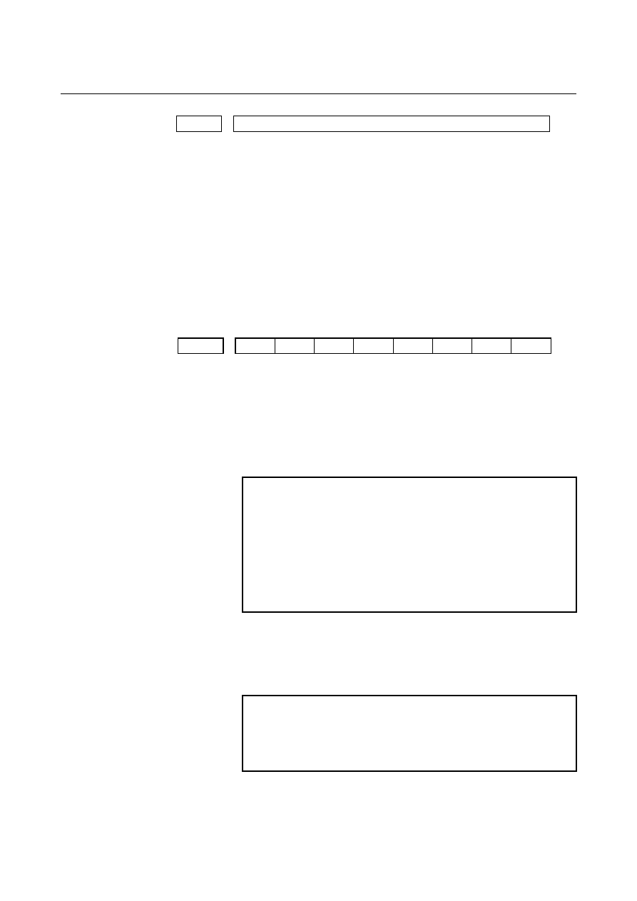
#7 #6 #5 #4 #3 #2 #1 #0 

1201 


FPC 

ZCL 


ZPR 


[Input type]  Parameter input 


[Data type]  Bit path 


        # 0 

ZPR

  Automatic setting of a coordinate system when the manual reference 

position return is performed 
0:  Not set automatically 
1: Set 

automatically 


NOTE 


ZPR is valid while a workpiece coordinate system 
function is not provided. If a workpiece coordinate 
system function is provided, making a manual 
reference position return always causes the 
workpiece coordinate system to be established on 
the basis of the workpiece zero point offset 
(parameters No. 1220 to No. 1226), irrespective of 
this parameter setting. 


        # 2 

ZCL

  Local coordinate system when the manual reference position return is 

performed 
0:  The local coordinate system is not canceled. 
1:  The local coordinate system is canceled. 
 

NOTE 


ZCL is valid when the workpiece coordinate system 
option is specified. In order to use the local 
coordinate system (G52), the workpiece coordinate 
system option is required. 


B-63944EN/03

 APPENDIX 

A.PARAMETERS


- 1997 - 

        # 3 

FPC

  When a floating reference position is set with a soft key, the relative 

position indication is: 
0:  Not preset to 0 (The relative position indication remains 

unchanged.) 

1:  Preset to 0. 


#7 #6 #5 #4 #3 #2 #1 #0 

1202 


G92 


[Input type]  Parameter input 


[Data type]  Bit path 


        # 2 

G92

  When the CNC has commands G52 to G59 specifying workpiece 

coordinate systems (optional function), if the G command for setting a 
coordinate system (G92 for M series, G50 for T series (or the G92 
command in G command system B or C)) is specified,   
0:  G command is executed and no alarm is issued. 
1:  G command is not executed and an alarm (PS0010) is issued. 
 

1240 

  Coordinate value of the reference position in the machine coordinate system


NOTE 


When this parameter is set, the power must be 
turned off before operation is continued. 


[Input type]  Parameter input 


[Data type]  Real axis 


[Unit of data]  mm, inch, degree (machine unit) 


[Minimum unit of data]  Depend on the increment system of the applied axis 

 [Valid data range]  9 digit of minimum unit of data (refer to standard parameter setting 

table (A)) 
(When the increment system is IS-B, -999999.999 to +999999.999) 
Set the coordinate values of the reference position in the machine 
coordinate system. 
 

A.PARAMETERS

 APPENDIX 

B-63944EN/03


- 1998 - 

1241 

  Coordinate value of the second reference position in the machine coordinate 

system 


1242 


Coordinate value of the third reference position in the machine coordinate 

system 


1243 

  Coordinate value of the fourth reference position in the machine coordinate 

system 


[Input type]  Parameter input 


[Data type]  Real axis 


[Unit of data]  mm, inch, degree (machine unit) 


[Minimum unit of data]  Depend on the increment system of the applied axis 

 [Valid data range]  9 digit of minimum unit of data (refer to standard parameter setting 

table (A)) 
(When the increment system is IS-B, -999999.999 to +999999.999) 
Set the coordinate values of the second to fourth reference positions in 
the machine coordinate system. 
 

1244 

  Coordinate value of the floating reference position in the machine coordinate

system 


[Input type]  Parameter input 


[Data type]  Real axis 


[Unit of data]  mm, inch, degree (machine unit) 


[Minimum unit of data]  Depend on the increment system of the applied axis 

 [Valid data range]  9 digit of minimum unit of data (refer to standard parameter setting 

table (A)) 
(When the increment system is IS-B, -999999.999 to +999999.999) 
Set the coordinate values of the floating reference position in the 
machine coordinate system. 
 

1250 


Coordinate system of the reference position used when automatic 

coordinate system setting is performed 


[Input type]  Parameter input 


[Data type]  Real axis 


[Unit of data]  mm, inch, degree (input unit) 


[Minimum unit of data]  Depend on the increment system of the applied axis 

 [Valid data range]  9 digit of minimum unit of data (refer to standard parameter setting 

table (A)) 
(When the increment system is IS-B, -999999.999 to +999999.999) 
Set the coordinate system of the reference position on each axis to be 
used for setting a coordinate system automatically. 
 

B-63944EN/03

 APPENDIX 

A.PARAMETERS


- 1999 - 

1260 


The shift amount per one rotation of a rotation axis 


NOTE 


When this parameter is set, the power must be 
turned off before operation is continued. 


[Input type]  Parameter input 


[Data type]  Real axis 


[Unit of data]  Degree 


[Minimum unit of data]  Depend on the increment system of the applied axis 

 [Valid data range]  0 or positive 9 digit of minimum unit of data (refer to the standard 

parameter setting table (B)) 
(When the increment system is IS-B, 0.0 to +999999.999) 
Set the shift amount per one rotation of a rotation axis. 
For the rotation axis used for cylindrical interpolation, set the standard 
value. 


#7 #6 #5 #4 #3 #2 #1 #0 

1300 


BFA 


NAL 

OUT 


[Input type]  Setting input 


[Data type]  Bit path 


        # 0 

OUT

  The area inside or outside of the stored stroke check 2 is set as an 

inhibition area 
0: Inside 
1: Outside 
 

        # 1 

NAL

  When the tool enters the inhibition area of stored stroke limit 1: 

0:  The overtravel alarm signal is not output. 
1:  The overtravel alarm signal is output, and the tool is decelerated 

to a stop. 


If manual operation is in progress at this time, the alarm is not 
output. 


NOTE 


When this parameter is set to 1, the alarm is issued 
if the tool enters stored stroke limit 1 during 
automatic operation. 


        # 7 

BFA

  When the stored stroke check 1, 2, or 3 alarm is issued, an interference 

alarm is issued with the inter-path interference check function (T 
series), or a chuck/tail stock barrier (T series) alarm is issued: 
0:  The tool stops after entering the prohibited area. 
1:  The tool stops before the prohibited area. 
 

A.PARAMETERS

 APPENDIX 

B-63944EN/03


- 2000 - 


#7 #6 #5 #4 #3 #2 #1 #0 

1301 


OTS 


NPC 


[Input type]  Setting input 


[Data type]  Bit path 


        # 2 

NPC

  As part of the stroke limit check performed before movement, the 

movement specified in G31 (skip) and G37 (automatic tool length 
measurement) blocks is: 
0: Checked 
1: Not 

checked 


NOTE 


This parameter is valid only when the option for 
stroke limit check before movement is selected. 


        # 6 

OTS

  When the overtravel alarm is issued: 

0:  The overtravel alarm signal is not output to the PMC. 
1:  The overtravel alarm signal is output to the PMC. 
 

1320  

Coordinate value I of stored stroke check 1 in the positive direction on each axis


1321  

Coordinate value I of stored stroke check 1 in the negative direction on each axis


[Input type]  Parameter input 


[Data type]  Real axis 


[Unit of data]  mm, inch, degree (machine unit) 


[Minimum unit of data]  Depend on the increment system of the applied axis 

 [Valid data range]  9 digit of minimum unit of data (refer to standard parameter setting 

table (A)) 
(When the increment system is IS-B, -999999.999 to +999999.999) 
Set the coordinate value of stored stroke check 1 on each axis in the + 
or - direction in the machine coordinate system. 
 

NOTE 

1  Specify diameter values for any axes for which 

diameter programming is specified. 

2  The area outside the area set by parameter No. 

1320 and No. 1321 is a prohibited area. 


B-63944EN/03

 APPENDIX 

A.PARAMETERS


- 2001 - 

1322  

Coordinate value of stored stroke check 2 in the positive direction on each axis


1323  

Coordinate value of stored stroke check 2 in the negative direction on each axis


[Input type]  Setting input 


[Data type]  Real axis 


[Unit of data]  mm, inch, degree (machine unit) 


[Minimum unit of data]  Depend on the increment system of the applied axis 

 [Valid data range]  9 digit of minimum unit of data (refer to standard parameter setting 

table (A)) 
(When the increment system is IS-B, -999999.999 to +999999.999) 
Set the coordinate value of stored stroke check 2 on each axis in the + 
or - direction in the machine coordinate system. 
 

NOTE 

1  Specify diameter values for any axes for which 

diameter programming is specified. 

2  Whether the inside area or outside area is a 

prohibited area is set using bit 0 (OUT) of 
parameter No. 1300. 


1324  

Coordinate value of stored stroke check 3 in the positive direction on each axis


1325  

Coordinate value of stored stroke check 3 in the negative direction on each axis


[Input type]  Setting input 


[Data type]  Real axis 


[Unit of data]  mm, inch, degree (machine unit) 


[Minimum unit of data]  Depend on the increment system of the applied axis 

 [Valid data range]  9 digit of minimum unit of data (refer to standard parameter setting 

table (A)) 
(When the increment system is IS-B, -999999.999 to +999999.999) 
Set the coordinate value of stored stroke check 3 on each axis in the + 
or - direction in the machine coordinate system. 
 

NOTE 

1  Specify diameter values for any axes for which 

diameter programming is specified. 

2  The area inside the area set by parameter No. 

1324 and No. 1325 is a prohibited area. 


A.PARAMETERS

 APPENDIX 

B-63944EN/03


- 2002 - 

1326  

Coordinate value II of stored stroke check 1 in the negative direction on each axis


1327  

Coordinate value II of stored stroke check 1 in the negative direction on each axis


[Input type]  Parameter input 


[Data type]  Real axis 


[Unit of data]  mm, inch, degree (machine unit) 


[Minimum unit of data]  Depend on the increment system of the applied axis 

 [Valid data range]  9 digit of minimum unit of data (refer to standard parameter setting 

table (A)) 
(When the increment system is IS-B, -999999.999 to +999999.999) 
Set the coordinate value of stored stroke check 1 on each axis in the + 
or - direction in the machine coordinate system. 
When the stored stroke check switch signal EXLM is set to 1, or the 
stored stroke check switch signal for each axis direction +EXLx is set 
to 1, parameter No. 1326 and No. 1327 are used for stroke check 
instead of parameter No.1320 and No. 1321. 
 

NOTE 

1  Specify diameter values for any axes for which 

diameter programming is specified. 

2  The area outside the area set by parameter No. 

1326 and No. 1327 is a prohibited area. 

3  The EXLM signal is valid only when bit 2 (LMS) of 

parameter No. 1300 is set to 1. 

4  The +EXLx signal is valid only when bit 0 (DLM) of 

parameter No. 1301 is set to 1. 


#7 #6 #5 #4 #3 #2 #1 #0 

1401 


RF0 


LRP 

RPD 


[Input type]  Parameter input 


[Data type]  Bit path 


        # 0 

RPD

  Manual rapid traverse during the period from power-on time to the 

completion of the reference position return. 
0:  Disabled (Jog feed is performed.) 
1: Enabled 
 

        # 1 

LRP

 Positioning 

(G00) 

0:  Positioning is performed with non-linear type positioning so that 

the tool moves along each axis independently at rapid traverse.   

1:  Positioning is performed with linear interpolation so that the tool 

moves in a straight line. 

When using three-dimensional coordinate conversion, set this 
parameter to 1. 
 

        # 4 

RF0

  When cutting feedrate override is 0% during rapid traverse, 

0:  The machine tool does not stop moving. 
1:  The machine tool stops moving. 
 

B-63944EN/03

 APPENDIX 

A.PARAMETERS


- 2003 - 


#7 #6 #5 #4 #3 #2 #1 #0 

1402 


JRV 


NPC 


[Input type]  Parameter input 


[Data type]  Bit path 


        # 0 

NPC

  Feed per revolution without the position coder (function for 

converting feed per revolution F to feed per minute F in the feed per 
revolution mode (G95)) is: 
0: Not 

used 

1: Used 
 

    # 4 

JRV

  Jog feed or incremental feed is 

0:  Performed at feed per minute. 
1:  Performed at feed per rotation. 
 

NOTE 

1  Specify a feedrate in parameter No.1423. 
2  For the machining center system, the option for 

threading/synchronous feed is required. 


#7 #6 #5 #4 #3 #2 #1 #0 

1403 


HTG 


[Input type]  Parameter input 


[Data type]  Bit path 


        # 5 

HTG

  The feedrate for helical interpolation/helical involute interpolation/ 

three-dimensional circular interpolation is: 
0:  Specified using the feedrate along the tangent to an arc/involute 

curve/three-dimensional arc 

1:  Specified using the feedrate along axes including a linear axis 

(specified axes other than the circular interpolation axis in the 
case of three-dimensional circular interpolation) 


#7 #6 #5 #4 #3 #2 #1 #0 


FM3 


1404 


[Input type]  Parameter input 


[Data type]  Bit path 


        # 2 

FM3

  The increment system of an F command without a decimal point in 

feed per minute is: 
0:  1 mm/min (0.01 inch/min for inch input) 
1:  0.001 mm/min (0.00001 inch/min for inch input) 


Content      ..     253      254      255      256     ..