FANUC Series 30i/300i/300is-MODEL A. Machining Center System. User's manual - page 248
 

  Index      Manuals     FANUC Series 30i/300i/300is-MODEL A. Machining Center System. User's manual (B-63944EN/03)


Search            copyright infringement  


Content      ..     246      247      248      249     ..


FANUC Series 30i/300i/300is-MODEL A. Machining Center System. User's manual - page 248


13

.

GRAPHIC

 FUNCTION

 OPERATION 

B-63944EN/03


- 1940 - 

Animation Graphic Screen Procedure 

Procedure 

1 Press 

the 

function 

key   (or 

  when a small MDI unit 

is used) to display the GRAPHIC PARAMETER (DYNAMIC 
GRAPHIC) screen. 

 
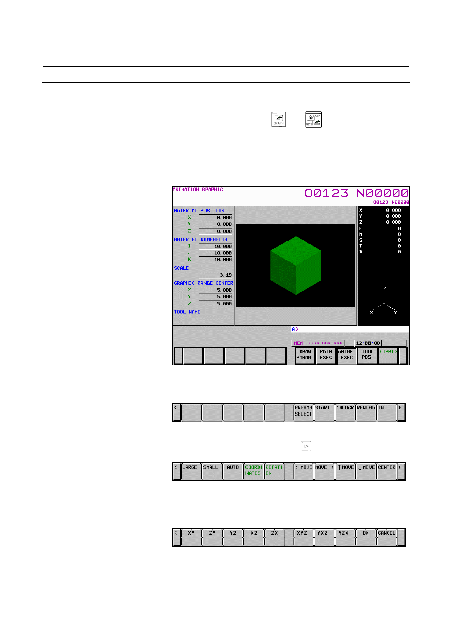
2  Press the [ANIME EXEC] soft key.  The ANIMATION 

GRAPHIC screen is displayed. 


Fig. 13.2.2.2 (b)    ANIMATION GRAPHIC screen 

 
3  Press the [(OPRT)] soft key.  The soft keys for tool path 

drawing are displayed. 


Fig. 13.2.2.2 (c)    ANIMATION GRAPHIC screen (operation) 


Press the continuous menu key 

  to display the soft keys for 

enlarging/reducing/moving the graphic range. 


Fig. 13.2.2.2 (d)    ANIMATION GRAPHIC screen 

  (enlarging/reducing/moving the graphic range) 


Press the [COORDINATES] soft key to display the soft keys for 
changing the graphic coordinate system. 


Fig. 13.2.2.2 (e)    ANIMATION GRAPHIC screen 

  (changing the graphic coordinate system) 


B-63944EN/03

 OPERATION 

13.GRAPHIC FUNCTION


- 1941 - 

6  Press the [ROTATION] soft key to display the soft keys for 

rotating the graphic coordinate system. 


Fig. 13.2.2.2 (f)    ANIMATION GRAPHIC screen 

  (rotating the graphic coordinate system) 

 
For the operation of each soft key, see the explanation. 
 

Explanation 

The operations listed below are the same operations as for the tool 
path drawing screen.  See the explanation of the tool path drawing 
screen. 


Graphic program selection 


Rewind of a drawing target program 


Starting / Stopping of drawing 


End of drawing 


  - Initializing a blank 

Press the [INIT.] soft key to initialize and return a drawn machining 
profile to the original blank figure. 
 

NOTE 

1  Blank initialization can also be performed by any of 

the following operations: 

- Start of drawing 
- Changing of the graphic coordinate system and 

graphic range by performing 
enlargement/reduction/movement/rotation 
operations 

- Change of screen 

2  A machining profile once drawn for a blank is 

erased when the screen or the path is switched. 


  - Enlarging/reducing the graphic range 

The following soft keys displayed by step 4 are used: 


[LARGE] soft key 
This soft key increases the scale to enlarge the graphic range. 


[SMALL] soft key 
This soft key decreases the scale to reduce the graphic range. 


[AUTO] soft key 
When the blank figure specified in a graphic parameter is input, 
this soft key automatically scales the graphic range so that the 
blank figure is contained within the graphic range. 
If no blank figure is input, this soft key has no effect. 


13

.

GRAPHIC

 FUNCTION

 OPERATION 

B-63944EN/03


- 1942 - 

NOTE 

1  Set the unit of scale for one enlargement/reduction 

operation in parameter No. 14713. 

2  An enlargement/reduction scale used here is set in 

the graphic parameter for scale. 


  - Moving the graphic range 

The following soft keys displayed by step 4 are used: 


[

MOVE] soft key 

This soft key moves the graphic range to left. 

 [MOVE

] soft key 

This soft key moves the graphic range to right. 


[

MOVE] soft key 

This soft key moves the graphic range upward. 


[

MOVE] soft key 

This soft key moves the graphic range downward. 


[CENTER] soft key 
This soft key returns the graphic range to the original position. 


NOTE 

1  Set the travel increment made by one horizontal 

move operation in parameter No. 14714. 

2  Set the travel increment made by one vertical move 

operation in parameter No. 14715. 

3  The graphic range modified here is not set in the 

graphic parameter for graphic range center. 


  - Changing the graphic coordinate system 

The following soft keys displayed by step 5 are used. 
A graphic coordinate system selected here is the same one as set in the 
graphic parameter for the graphic coordinate system. 


[XY] soft key 
This soft key selects the graphic coordinate system of XY (with a 
setting of 0). 


[ZY] soft key 
This soft key selects the graphic coordinate system of ZY (with a 
setting of 1). 


[YZ] soft key 
This soft key selects the graphic coordinate system of YZ (with a 
setting of 2). 


[XZ] soft key 
This soft key selects the graphic coordinate system of XZ (with a 
setting of 3). 


[ZX] soft key 
This soft key selects the graphic coordinate system of ZX (with a 
setting of 4). 


[XYZ] soft key 
This soft key selects the graphic coordinate system of XYZ (with 
a setting of 5). 

B-63944EN/03

 OPERATION 

13.GRAPHIC FUNCTION


- 1943 - 


[YXZ] soft key 
This soft key selects the graphic coordinate system of YXZ (with 
a setting of 6). 


[YZX] soft key 
This soft key selects the graphic coordinate system of YZX (with 
a setting of 7). 


[OK] soft key 
This soft key changes the current graphic coordinate system to 
the graphic coordinate system selected by one of the soft keys 
above. 


[CANCEL] soft key 
This soft key cancels the graphic coordinate system selected by 
one of the soft keys above to return to the original graphic 
coordinate system. 


NOTE 


The graphic coordinate system selected here is set 
in the graphic parameter for the graphic coordinate 
system. 


  - Rotating the graphic coordinate system 

The following soft keys displayed by step 6 are used. 


[

] soft key 

This soft key rotates the graphic coordinate system upward. 


[

] soft key 

This soft key rotates the graphic coordinate system downward. 


[

] soft key 

This soft key rotates the graphic coordinate system to left. 


[

] soft key 

This soft key rotates the graphic coordinate system to right. 


[CW] soft key 
This soft key rotates the graphic coordinate system clockwise. 


[CCW] soft key 
This soft key rotates the graphic coordinate system 
counterclockwise. 


[OK] soft key 
This soft key changes the rotation angle of the current graphic 
coordinate system to the one set by one of the soft keys above. 


[CANCEL] soft key 
This soft key cancels the rotation of the graphic coordinate 
system performed by one of the soft keys above to return to the 
original graphic coordinate system. 


NOTE 

1  Set the travel increment made by one rotation 

operation in parameter No. 14716. 

2  The rotation angle of the graphic coordinate system 

set here is not set in the graphic parameter for 
rotation angle. 


13

.

GRAPHIC

 FUNCTION

 OPERATION 

B-63944EN/03


- 1944 - 

  - Drawing of a tool 

In animation drawing, not only a blank figure but also a tool figure is 
drawn in three dimensions. 
 

NOTE 


The following function is necessary to draw in the 
tool figure. 
- Tool geometry size data 100/300 pairs 


    Figure data 

For tool figure drawing, the following data is used: 


Tool geometry size data 100/300 pairs 


Tool compensation data (tool-nose radius compensation value, 
virtual tool tip direction, cutter compensation value) 

 Parameters 

The table below indicates the drawable types of tools and figure data 
of each type of tool. 
 

Table 13.2.2.2 (a)    List of drawable tools (for turning) 

Tool name 

Tool geometry size data 

Tool compensation

Parameter No. 

General-purpose tool 

Setting  Tip 

position 

No.27350#0 


Cutting edge angle 


Cutting edge 
length 

No.27351 


Tool angle 


Holder length 

No.27352 


 Holder 

width 

No.27353 


Holder length 2 

No.27354 


Holder width 2 

No.27355 

Threading tool 

Setting 


Tip position 

No.27356#0 


Tool angle 


Cutting edge width 

No.27357 


 Holder 

length 

No.27358 


 Holder 

width 

No.27359 

Grooving tool 

Setting 


Tip position 

No.27360#0 


Tip width 


Holder length 

No.27361 


Tip length 


Holder width 

No.27362 

Round-nose tool 

Setting 

Tool-nose radius 

Tip position 

No.27363#0 


Tip length 

Virtual tool tip Holder 

length 

No.27364 


 Holder 

width 

No.27365 

Point nose straight 

Setting 


Tip position 

No.27366#0 

tool 

Cutting edge angle 


Cutting edge 
length 

No.27367 


Tool angle 


Holder length 

No.27368 


 Holder 

width 

No.27369 


Holder length 2 

No.27370 


Holder width 2 

No.27371 

Versatile tool 

Setting 


Tip position 

No.27384#0 


Tip width 


Holder length 

No.27385 


Tip length 


Holder width 

No.27386 


B-63944EN/03

 OPERATION 

13.GRAPHIC FUNCTION


- 1945 - 

Table 13.2.2.2 (b)    List of drawable tools (for milling) 

Tool name 

Tool geometry size data 

Cutter compensation 

Parameter No. 

Drill Setting 

Diameter Tip 

length 

No.27372 

 Tool 

angle 


counter sink tool 

Setting 

Small diameter 

Tool angle 

No.27375 


Cutter diameter 


Tip length 

No.27376 


Cutter 

length 

No.27377 


Shank 

length 

No.27378 


Shank 

diameter 

No.27379 

Flat end mill 

Setting 

Diameter 

Tip length 

No.27373 

Ball end mill 

Setting 

Diameter 

Tip length 

No.27380 

Tap Setting 

Diameter  Tip 

length 

No.27374 

Reamer Setting 

Diameter 

Tip 

length 

No.27381 

Boring tool 

Setting 

Diameter 

Tip length 

No.27382 

Face mill 

Setting 

Diameter 

Tip length 

No.27383 


NOTE 


In lathes system, the round-nose tool and milling 
tools can be drawn only when the cutter 
compensation/tool-nose radius compensation 
function is provided. 


    Timing of drawing 

If a code indicated below is specified during drawing execution, a tool 
figure is drawn according to the tool geometry size data that has the 
same number as the code. 


With a lathe system   
T code command 
If three numbers, namely, a tool number, tool geometry offset 
number, and tool wear offset number, are specified in a T code, 
the tool geometry size data that has the same number as the tool 
geometry offset number is obtained. 
 

NOTE 


When the tool management function is 
provided, a tool offset is specified with a D 
code. So, the tool geometry size data that has 
the offset number indicated by the D code is 
obtained. 


With a machining center system 
D code command 

 
If the tool geometry size data corresponding to a specified number 
does not exist or the tool geometry size data is not set correctly, tool 
drawing is disabled with the warning "ILLEGAL SETTING OF 
TOOL FIGURE DATA". 
 

13

.

GRAPHIC

 FUNCTION

 OPERATION 

B-63944EN/03


- 1946 - 

13.2.3 

Programmable Data Input (G10) for Blank Figure Drawing 

Parameters 


Overview 

Each of the drawing parameters for a blank figure, a position, and 
dimensions that are for the automatic scaling of the drawing areas of 
tool path drawing and animation drawing with the dynamic graphic 
display function can be set with an NC program, using the 
programmable data input command (G10 command). 
 

Format 

G10 L90 P_ 

IP

_ I_ J_ K_ ; 

P_ : 

Blank 

figure 

IP

: Addresses of the basic three axes and the 

reference position of a blank 

I_,J_,K_ : Dimensions of a blank 


NOTE 

1  This command is enabled only during the execution 

of drawing. It is ignored during normal automatic 
operation. 

2  This command is a one-shot G code. 
3  This command must be specified in a single block. 


Explanation


  - Blank figure (P_) 

Specify the type of a blank figure with either of the following settings 
for shapes. 
 

Setting Figure 

Column or cylinder 

(parallel with the Z-axis) 

1 Rectangular 

parallelepiped 

 
The specified value is set in parameter No. 11343. 
 

  - Reference position of a blank (

IP

_) 

Specify the reference position of a blank with coordinates (X,Y,Z) in 
the workpiece coordinate system. 
 

NOTE 


Specify the reference position of a blank with 
coordinates (X,Y,Z) in the machine coordinate 
system in case of bit 3 (BGM) of parameter 
No.11329=1. 

 
The specified value is set in parameter No. 11344. 

B-63944EN/03

 OPERATION 

13.GRAPHIC FUNCTION


- 1947 - 

  - Dimensions of a blank (I_,J_,K_) 

For the shape of each blank, specify the dimensions of the blank as 
follows: 
 

Blank figure

Address I 

Address J 

Address K 

Rectangular 

parallelepiped

Length in X-axis 

direction 

Length in Y-axis 

direction 

Length in Z-axis 

direction 

Column 

Diameter of 

column 

Length of 

column 

Cylinder 

Diameter of outer 

circle of cylinder 

Diameter of inner 

circle of cylinder 

Length of 

cylinder 

 
The specified value are set in parameter No.11345 (address I), 
parameter No.11346 (address J), and parameter No.11347 (address K). 
 

  - Relationship between the position and dimensions of a blank 

The relationship between the position and dimensions of a blank is 
shown in the figure below. 


J

K

: Reference position (X,Y,Z)

I

X

Z

Y

X

Y

J

K


  - Operation to be performed when this command is issued 

When this command is executed in the background operation, the 
specified values are set in the drawing parameters for the blank figure, 
reference position, and dimensions that correspond to the specified 
arguments, and the drawing area is automatically set again with the 
values set. 
This causes this command and subsequent commands to perform 
drawing in the new drawing area. 
 

NOTE 


Before this command, drawing is performed as 
described below. 

-  The tool path is erased. 
-  In animation drawing, the blank figure is 

initialized. 

-  The drawing start position and the tool figure 

become ineffective. 


Thus, issue this command at the start of a drawing 
program. 


Content      ..     246      247      248      249     ..