FANUC Series 30i/300i/300is-MODEL A. Machining Center System. User's manual - page 189
 

  Index      Manuals     FANUC Series 30i/300i/300is-MODEL A. Machining Center System. User's manual (B-63944EN/03)


Search            copyright infringement  


Content      ..     187      188      189      190     ..


FANUC Series 30i/300i/300is-MODEL A. Machining Center System. User's manual - page 189


12.SETTING AND DISPLAYING DATA

 OPERATION 

B-63944EN/03


- 1468 - 

12.2.1.1 

Displaying the executed block 


Overview 

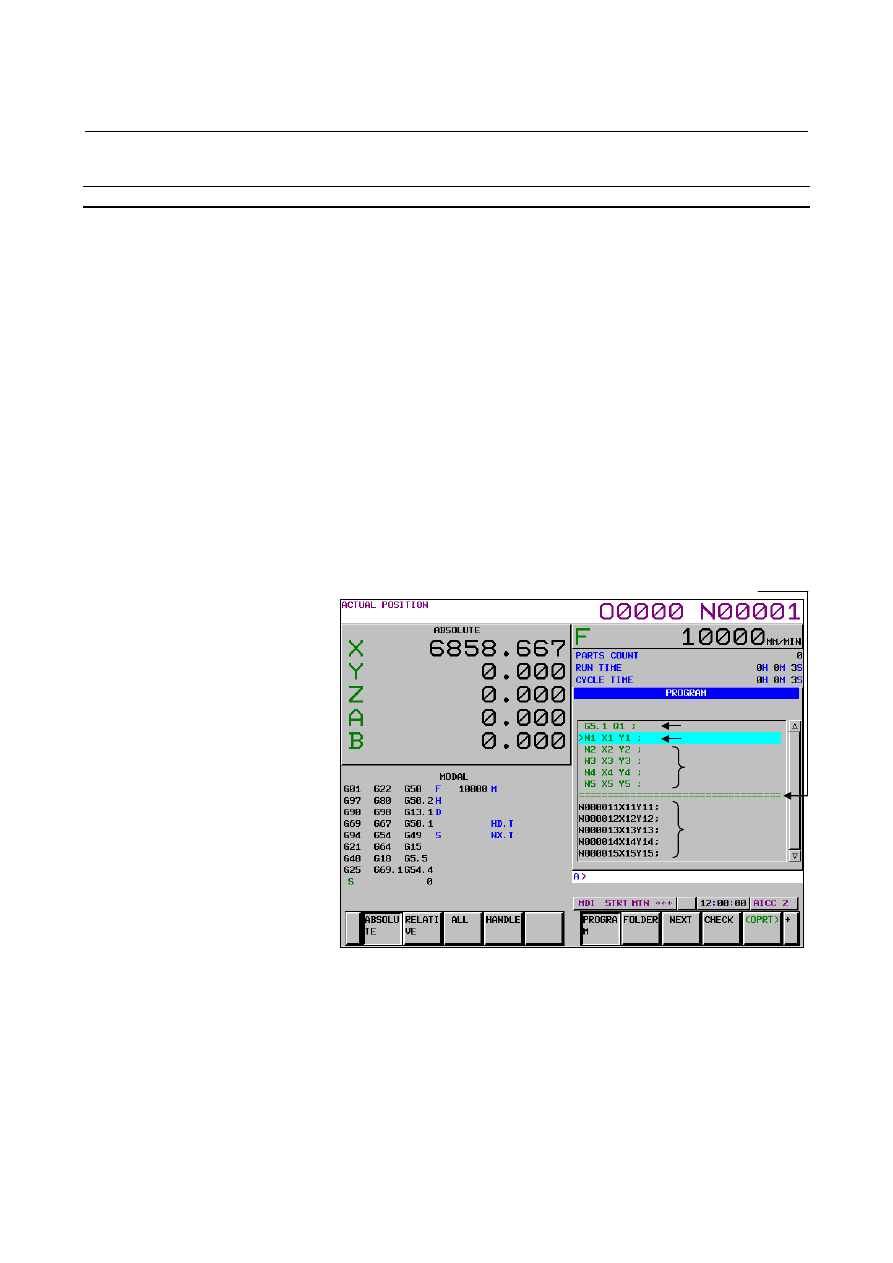
When the program being executed is displayed, one executed block 
can be displayed. This function can be enabled by setting bit 3 (FPD) 
of parameter No. 11308. 
 
The program screen shows the following: 

 Executed 

block 


Block being executed 

 Look-ahead 

block(*) 

 Non-look-ahead 

block 

(*) For details on look-ahead, see the explanation "Program 

look-ahead" below. 

 
The executed block is displayed on the top of the screen, and ">" is 
shown in front of the block being executed, across which the cursor is 
placed. Below the block being executed, look-ahead blocks are 
displayed. Below them, non-look-ahead blocks are displayed. 
There is a dividing line between the look-ahead blocks and the 
non-look-ahead blocks. 


Fig. 12.2.1.1 (b) Screen for displaying the program being executed (MDI 

mode) 


Look-ahead block

Executed block

Block being executed

Non-look-ahead 
block 

Dividing line 

B-63944EN/03

 OPERATION 

12.SETTING AND DISPLAYING DATA


- 1469 - 


Fig. 12.2.1.1 (c) Screen for displaying the program being executed (MEM 

mode) 


Explanation 
 - Program look-ahead 

When an automatic operation cycle starts, a program is executed as 
described below. 
<1>  The command of one block is read from the specified program. 
<2>  The read command is analyzed and converted to executable data. 
<3>  The command of the block is executed. 
 
During execution of the command, steps <1> and <2> are performed 
for the next block in advance. Upon completion of the current block, 
execution of the next block can be started immediately. This 
processing is referred to as look-ahead or buffering. 
 
The number of look-ahead blocks depends on the processing status or 
parameters. 


12.SETTING AND DISPLAYING DATA

 OPERATION 

B-63944EN/03


- 1470 - 

12.2.2 

Editing a Program 

 
A program can be edited in the EDIT mode. 
Two modes of editing are available. One mode is word editing, which 
performs word-by-word editing. The other is character editing, which 
performs character-by-character editing. 
For program creation and editing operation, see Chapter III-9, 
“CREATING PROGRAMS” and Chapter III-10, “EDITING 
PROGRAMS”. 
 

Displaying the program editing screen 

Procedure 

Press function key 

  to display the program screen. 

Press chapter selection soft key [PROGRAM].   


 - Word editing 

Editing operations such as text insertion, modification, and deletion, 
and cursor movements are performed on a word-by-word basis. 


Fig. 12.2.2 (a) Program word editing screen (10.4-inch) 


B-63944EN/03

 OPERATION 

12.SETTING AND DISPLAYING DATA


- 1471 - 

 - Character editing 

Program editing operations and cursor movements are performed on a 
character-by-character basis as with a general text editor. 
Text is input directly to the cursor position instead of using the key 
input buffer. 


Fig. 12.2.2 (b) Program character editing screen (10.4-inch) 


Switching between program editing modes 

You can switch between word editing and character editing with soft 
keys. 
 

Procedure 

Press function key 

  to display the program screen. 

Press chapter selection soft key [PROGRAM].   

Press operation soft key [(OPRT)].   

Pressing operation soft key [CHANGE EDITOR] switches the 
editing mode between word editing and character editing. 


12.SETTING AND DISPLAYING DATA

 OPERATION 

B-63944EN/03


- 1472 - 

12.2.3 

Program Screen for MDI Operation 

 
During MDI operation or editing of an MDI operation program in the 
MDI mode, the program currently being executed mode is displayed. 
For MDI operation, see Section III-4.2, “MDI Operation”. 
 

Procedure for displaying the program screen for MDI operation 

Procedure 

Press function key 

Press chapter selection soft key [PROGRAM].   
The program input from the MDI is displayed. 


Fig. 12.2.3 (a) MDI operation program screen (10.4-inch) 


B-63944EN/03

 OPERATION 

12.SETTING AND DISPLAYING DATA


- 1473 - 

12.2.4 

Program Folder Screen 

 
A list of programs registered in the program memory is displayed. 
For the program folder screen, see Chapter III-11, “PROGRAM 
MANAGEMENT”. 
 

Displaying the program folder screen 

Procedure 

Press function key 

Press chapter selection soft key [FOLDER].   


Fig. 12.2.4 (a) Program folder screen (10.4-inch) 


12.SETTING AND DISPLAYING DATA

 OPERATION 

B-63944EN/03


- 1474 - 

12.2.4.1 

Split display on the program folder screen 


Overview 

On the program folder screen, the folder information display can be 
split into two folder information views, upper and lower, as shown in 
the figure below. This function is enabled by setting bit 1 (MLD) of 
parameter No. 11318 to 1. 


Fig. 12.2.4.1 (a) Program folder screen (split-display screen)(10.4-inch) 

 
On the split folder display, file information about different sets of 
devices or folders can be shown in different views at the same time, so 
you can copy or move files easily. 
 

B-63944EN/03

 OPERATION 

12.SETTING AND DISPLAYING DATA


- 1475 - 

Example of copying a file from the CNC MEM to the Data Server 


Procedure 

<1>  Change to a destination folder on the Data Server. 
<2> Change to a folder on the CNC_MEM that contains a file you 

want to copy. 

<3>  Select the file. 
<4>  Copy the file. 
 

<2> 

<1> 

<3>

<4>


Content      ..     187      188      189      190     ..