FANUC Series 30i/300i/300is-MODEL A. Machining Center System. User's manual - page 159
 

  Index      Manuals     FANUC Series 30i/300i/300is-MODEL A. Machining Center System. User's manual (B-63944EN/03)


Search            copyright infringement  


Content      ..     157      158      159      160     ..


FANUC Series 30i/300i/300is-MODEL A. Machining Center System. User's manual - page 159


6.SAFETY FUNCTIONS

 OPERATION 

B-63944EN/03


- 1228 - 

6.5.3.5 

Workpiece shift range setting screen 


T


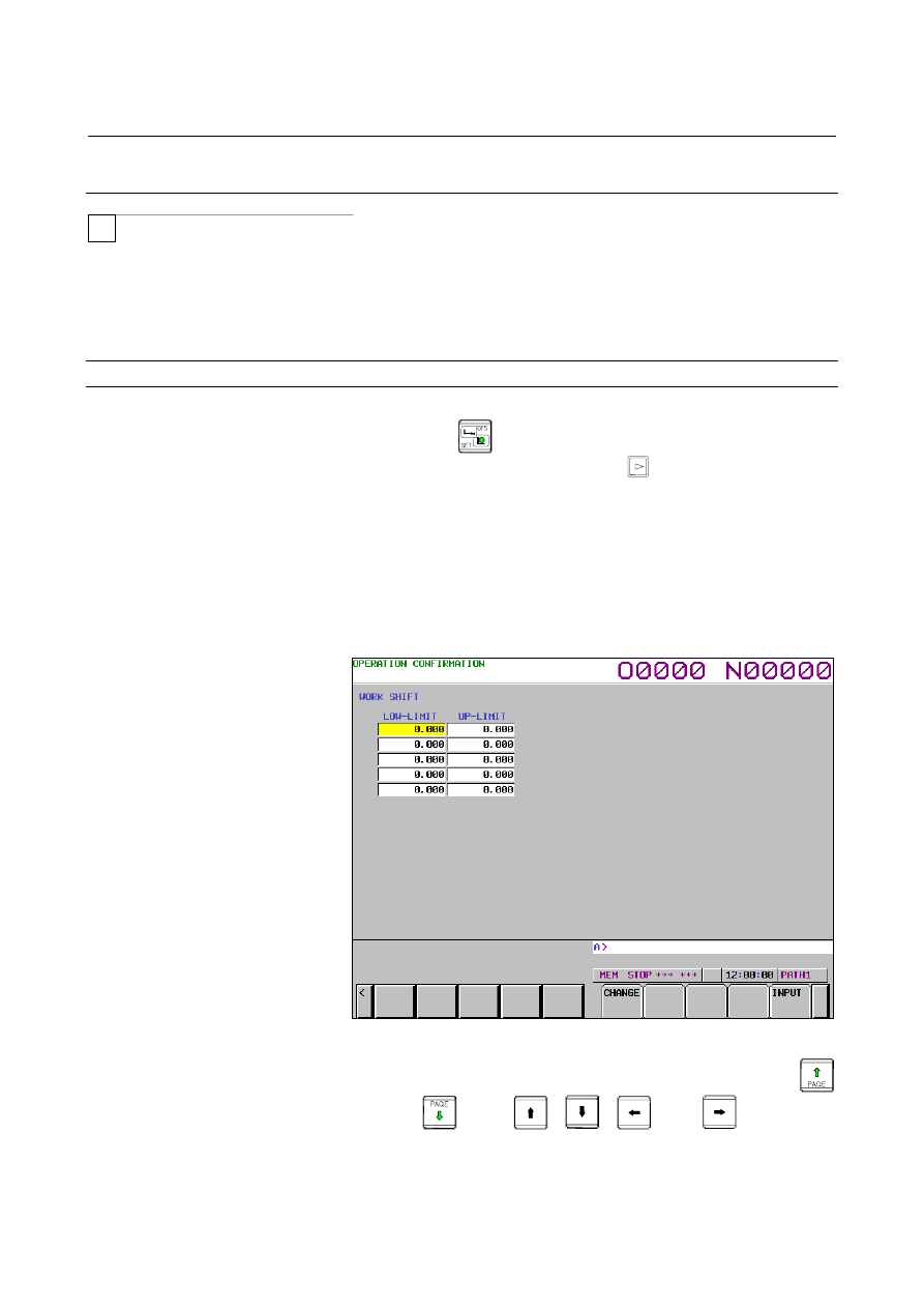
In the case of a lathe system, this screen displays the setting status of 
shift effective data ranges of workpiece shift coordinate systems and 
lets you change their settings.    (Hereinafter, the screen is referred to 
as the workpiece shift range setting screen.) 
An offset value range can be specified for each axis. 
 

Displaying and setting workpiece shift input ranges 

Procedure 

1 Press 

the 

 function key. 

2  Press the continuous menu key 

 at the right edge of the 

screen several times until the [GUARD] soft key is displayed. 

3  Click the [GUARD] soft key.  The setting screen that was 

displayed last with relation to any operation confirmation 
function is displayed (the operation confirmation function setting 
screen is the first such screen that appears after the system is 
restarted). 

If any screen other than the workpiece shift range setting screen 
is displayed, click the [WORK SHIFT] soft key.  The 
workpiece shift range setting screen is displayed. 


Fig. 6.5.3.5 (a) Workpiece shift range setting screen 


Move the cursor to the item you want to set, by using the 


and 

 keys, 

, and 

 keys, or the 

[SWITCH] soft key. 

6  Press the MDI key, enter necessary data, and then click the 

[INPUT] soft key. 


B-63944EN/03

 OPERATION 

6.SAFETY FUNCTIONS


- 1229 - 

If the set effective data range is invalid for any of the reasons listed 
below, the input data range check is not performed normally and the 
input data is rejected. 

  The upper and lower limit values are reversed. 

 
Also, the input data range check is invalidated in the following cases. 

  The upper and lower offset limit values are identical. 


Explanation 
  - What to set for the workpiece shift 

For the workpiece shift, an effective data range is specified using the 
following two items. 

Displayed item

What to set 

LOW-LIMIT

AXIS 
NAME UP-LIMIT 

Specify a valid workpiece shift coordinate system shift 
value range on each axis. 


 OPERATION 

B-63944EN/03


- 1230 - 

7. ALARM AND SELF-DIAGNOSIS 

FUNCTIONS 

ALARM AND SELF-DIAGNOSIS 
FUNCTIONS 

 
When an alarm occurs, the corresponding alarm screen appears to 
indicate the cause of the alarm. The causes of alarms are classified by 
error codes and number. Up to 60 previous alarms can be stored and 
displayed on the screen (alarm history display). 
The system may sometimes seem to be at a halt, although no alarm is 
displayed. In this case, the system may be performing some 
processing. The state of the system can be checked using the 
self-diagnosis function. 
 

B-63944EN/03

 OPERATION 


- 1231 - 

7.ALARM AND SELF-DIAGNOSIS 

FUNCTIONS

7.1 

ALARM DISPLAY 


Explanation 
 - Alarm screen 

When an alarm is issued, the display changes to the alarm screen.  
Two alarm screens "DETAIL" and "ALL PATH" are provided.    You 
can choose one of the screens by pressing the corresponding soft key. 
 

 Detail 

screen 


Alarm information for the currently selected path is displayed. 


Fig. 7.1 (a)    Alarm detail screen 


All path screen 


Alarm information for all paths is displayed sequentially from 
path 1. 


Fig. 7.1 (b)    All path screen 

 OPERATION 

B-63944EN/03


- 1232 - 

7. ALARM AND SELF-DIAGNOSIS 

FUNCTIONS 

  - Displaying an alarm screen 

ALM is sometimes indicated in the bottom part of the screen display 
without displaying an alarm screen. 


Fig. 7.1 (c)    Parameter screen 


In this case, display the alarm screen by following the steps below. 
 

Press the function key 

Press the soft key [ALARM]. 

Pressing the [ALARM] soft key changes the screen display to the 
"DETAIL" screen (or the alarm screen selected previously), and 
the [DETAIL] and [ALL PATH] soft keys appears. 


Pressing the [DETAIL] soft key displays the "DETAIL" 
screen. 

  Pressing the [ALL PATH] soft key displays the "ALL 

PATH" screen. 


If the number of paths is 1, pressing the [ALARM] soft key 
displays the "DETAIL" screen, but the [ALARM] soft key 
indication remains unchanged. 

You can change pages by using the page key. 


 - Releasing alarm 

The cause of an alarm can be determined from the error code, number, 
and associated message.    To release the alarm, generally correct the 
cause, then press the reset key. 
 

  - Error code and number 

The type of an alarm is indicated by an error code and number. 
Example:  PS0010, SV0004, etc. 
For details, see Appendix G, "ALARMS". 
 

B-63944EN/03

 OPERATION 


- 1233 - 

7.ALARM AND SELF-DIAGNOSIS 

FUNCTIONS

7.2 

ALARM HISTORY DISPLAY 

 
Up to 60 alarms (in 10 screen pages) issued by the CNC including the 
latest alarm are stored and displayed on the screen. 
The display procedure is explained below. 
 

Alarm history display 

Procedure 

Press the function key 

Press the soft key [HISTRY]. 
An alarm history is displayed. 
The following information is displayed: 
<1>  Date and time of alarm issuance 
<2> Alarm type 
<3> Alarm number 
<4>  Alarm message (sometimes not displayed depending on the 

alarm) 

<5> Page No. 

You can change pages by using the page key. 


Fig. 7.2 (a)    Alarm history screen 


 OPERATION 

B-63944EN/03


- 1234 - 

7. ALARM AND SELF-DIAGNOSIS 

FUNCTIONS 

7.3 

CHECKING BY DIAGNOSTIC DISPLAY 

 
The system may sometimes seem to be at a halt, although no alarm has 
occurred. In this case, the system may be performing some processing.   
Diagnostic display can be used to check the system status.   
 

Procedure for Diagnostic display 

Procedure 

Press the function key 

Press the soft key [DGNOS]. 

The diagnosis screen has more than 1 pages. Select the screen by 
the following operation. 
(1)  Change the page by the page change key. 
(2)  Method by soft key 

  Key input the number of the diagnosis data to be 

displayed. 


Press the soft key [NO.SRH]. 


Fig. 7.3 (a)    Diagnostic display 


B-63944EN/03

 OPERATION 


- 1235 - 

7.ALARM AND SELF-DIAGNOSIS 

FUNCTIONS

7.4 

RETURN FROM THE ALARM SCREEN 


7.4.1 

Return from the Alarm Screen 


When alarms are cleared or function key 

 is pressed on the 

alarm screen, the screen displayed before the alarm screen appears. 
To enable this function, set bit 4 (ADC) of parameter No. 11302 is set 
to 1. 
 

Switching between screens when alarms are cleared 

When all alarms are cleared on the alarm screen, the screen displayed 
before the alarm screen appears again. 
When the alarm screen was displayed automatically due to occurrence 
of an alarm, the screen displayed immediately before the alarm 
appears again. 
When the alarm screen was displayed by pressing function key 


during occurrence of an alarm, the screen displayed immediately 
before the alarm appears again. 
 

(Example) 


NOTE 


Even if alarms are cleared when the alarm screen 
is not displayed, the current screen is not changed. 


ALARM screen 

PROGRAM screen 

Occurrence of 

an alarm 

Clearing of 

alarm 


Content      ..     157      158      159      160     ..