FANUC Series 30i/300i/300is-MODEL A. Machining Center System. User's manual - page 135
 

  Index      Manuals     FANUC Series 30i/300i/300is-MODEL A. Machining Center System. User's manual (B-63944EN/03)


Search            copyright infringement  


Content      ..     133      134      135      136     ..


FANUC Series 30i/300i/300is-MODEL A. Machining Center System. User's manual - page 135


3.MANUAL OPERATION

 OPERATION 

B-63944EN/03


- 1036 - 

3.4 

MANUAL HANDLE FEED 

 
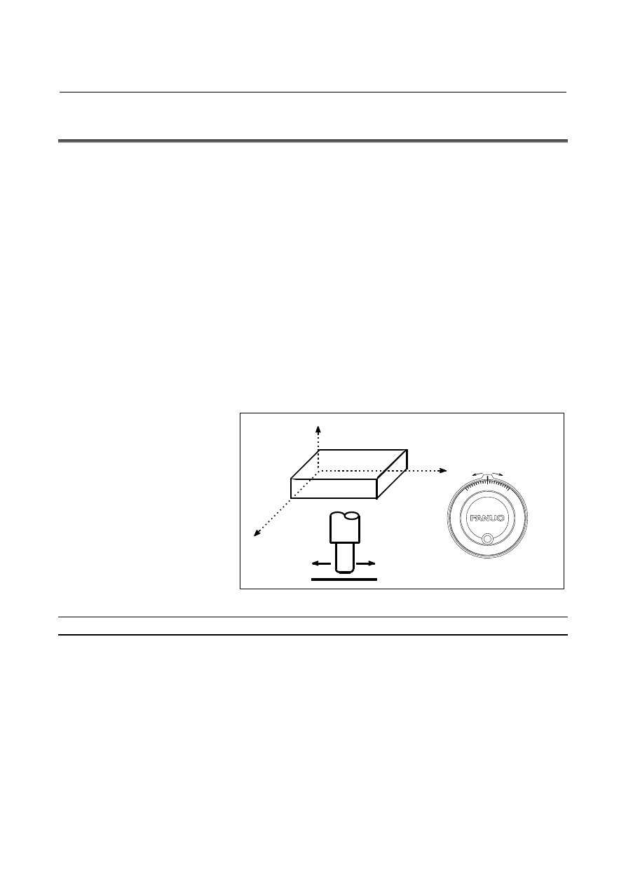
In the handle mode, the tool can be minutely moved by rotating the 
manual pulse generator on the machine operator's panel. Select the 
axis along which the tool is to be moved with the handle feed axis 
selection switches. 
The minimum distance the tool is moved when the manual pulse 
generator is rotated by one graduation is equal to the least input 
increment. One of four types of magnifiers selected with the manual 
handle feed move distance select signal can be applied.    With bit 2 
(HNT) of parameter No. 7103, the minimum distance can be further 
10 times greater. 
The number of manual pulse generators depends on the option as 
follows: 


Control on 1 manual handle: Up to 1 


Control on 2 or 3 manual handles: 


Up to 3 (Up to three manual pulse generators can be moved at a 
time.) 


Control on 2 to 5 manual handles: 


Up to 5 (Up to five manual pulse generators can be moved at a 
time.) 


Manual pulse generator


Fig. 3.4 (a)    Manual handle feed 


Procedure for manual handle feed 

Procedure 

Press the handle switch, one of the mode selection switches. 

Select the axis along which the tool is to be moved by pressing a 
handle feed axis selection switch. 

Select the magnification for the distance the tool is to be moved 
by pressing a handle feed magnification switch.    The minimum 
distance the tool is moved when the manual pulse generator is 
rotated by one graduation is equal to the least input increment.     

4  Move the tool along the selected axis by rotating the handle. 

Rotating the handle 360 degrees moves the tool the distance 
equivalent to 100 graduations. 

The above is an example. Refer to the appropriate manual provided by 
the machine tool builder for the actual operations. 

B-63944EN/03

 OPERATION 

3.MANUAL OPERATION


- 1037 - 


Explanation 
  - Availability of manual pulse generator in Jog mode (JHD) 

Bit 0 (JHD) of parameter No.7100 enables or disables the manual 
handle feed in the JOG mode. 
When bit 0 (JHD) of parameter No.7100 is set 1,both manual handle 
feed and incremental feed are enabled. 
 

  - Manual handle feed in TEACH IN JOG mode (THD) 

By setting bit 1 (THD) of parameter No. 7100, manual handle feed in 
TEACH IN JOG mode can be enabled or disabled. 
 

  - When manual handle feed exceeding the rapid traverse rate is specified   

The amount of pulses exceeding the rapid traverse rate can be saved 
by CNC as B. And amount of pulses B will be output as pulses C.   


Rapid 
traverse 
rate 

A:  Amount of pulses corresponds to value of

Rapid Traverse Rate. 

B:  Amount of pulses accumulated in CNC. 
C:  Amount of pulses the same as B. 

A

B

C


Fig. 3.4 (b)    Amount of pulses output by CNC in Manual Handle Feed 

 
Amount of pulses B is calculated in 2 cases as following: 
 
In case of 
1)  Parameter No.7117 = 0 
 

The feedrate is clamped at the Rapid Traverse Rate and 
generated pulses exceeding the Rapid Traverse Rate are 
ignored (B=0). 

In case of 
2)  Parameter No.7117 > 0


The feedrate is clamped as the Rapid Traverse Rate, but the 
pulses exceeding the Rapid Traverse Rate is not ignored. Amount 
of pulses accumulated in CNC is calculated as following. 
(Although the rotation of manual pulse generator is stopped, if 
there is pulses accumulated in CNC, it will be output and the tool 
will move as long as amount of it.)


Magnification set by MP1

MP2<Gn019.4,5> is m, value of 

parameter No.7117 is n. 


n < m: Clamping is set performed at value of parameter 
No.7117. 

3.MANUAL OPERATION

 OPERATION 

B-63944EN/03


- 1038 - 

 n 

 m: Amount A+B, shown in figure, which’s value is 

multiple of m and small than n. As a result, clamping is 
performed as an integral multiple of the selected 
magnification. 


n

A

B

Pulses over (k

m) will be ignored

A:  Amount of pulses the same 

as Rapid Traverse Rate. 

B:  Amount of pulses saved in 

CNC. 

k :  Integer number 

A

B=k


Fig. 3.4 (c)    Amount of pulses exceeding the Rapid Traverse Rate   

(n 

 m) 


NOTE 


Due to change of mode, clamping can be 
performed not as an integral multiple of the 
selected magnification. 


The distance the tool moves may not match the 
graduations on the manual pulse generator. 


  - Upper feedrate limit in manual handle feed 

The upper feedrate limit depends on the input signal (maximum 
manual handle feedrate switch signal HNDLF) from the PMC as 
follows: 


When HNDLF is set to 0, the feedrate is clamped to the manual 
rapid traverse rate (parameter No. 1424). 


When HNDLF is set to 1, the feedrate is clamped to the feedrate 
set in parameter No. 1434. 


  - Movement direction of an axis to the rotation of MPG (HNGx) 

Bit 0 (HNGx) of parameter No 7102 switches the direction of MPG in 
which the tool moves along an axis, corresponding to the direction in 
which the handle of the manual pulse generator is rotated. 
 
This parameter is valid only for the following functions: 


Manual handle feed 


Manual handle interruption 


Limitation 

 WARNING 


Rotating the handle quickly with a large 
magnification such as 

×

100 moves the tool too fast. 

The feedrate is clamped at the rapid traverse 
feedrate. 


B-63944EN/03

 OPERATION 

3.MANUAL OPERATION


- 1039 - 

NOTE 


Rotate the manual pulse generator at a rate of five 
rotations per second or lower. If the manual pulse 
generator is rotated at a rate higher than five 
rotations per second, the tool may not stop 
immediately after the handle is no longer rotated or 
the distance the tool moves may not match the 
graduations on the manual pulse generator. 


3.MANUAL OPERATION

 OPERATION 

B-63944EN/03


- 1040 - 

3.5 

MANUAL ABSOLUTE ON AND OFF 

 
Whether the distance the tool is moved by manual operation is added 
to the coordinates can be selected by turning the manual absolute 
switch on or off on the machine operator's panel. When the switch is 
turned on, the distance the tool is moved by manual operation is added 
to the coordinates. When the switch is turned off, the distance the tool 
is moved by manual operation is not added to the coordinates. 

O

P1

P2

Y axis

X axis

Manual operation

The coordinates values change by the
amount of manual operation.


Fig. 3.5 (a)    Coordinates with the switch ON 


The coordinates do not change.

X2

X1

Y1

Y2

P1

P2

O1

O2


Fig. 3.5 (b)    Coordinates with the switch OFF 


B-63944EN/03

 OPERATION 

3.MANUAL OPERATION


- 1041 - 

Explanation 

The following describes the relation between manual operation and 
coordinates when the manual absolute switch is turned on or off, using 
a program example. 

G01G90 X100.0Y100.0F010 ;

<1>

X200.0Y150.0

 ;

<2>

X300.0Y200.0

;

<3>


Fig. 3.5 (c)    Program example 

The subsequent figures use the following notation: 
            Movement of the tool when the switch is on 
            Movement of the tool when the switch is off 
The coordinates after manual operation include the distance the tool is 
moved by the manual operation.    When the switch is off, therefore, 
subtract the distance the tool is moved by the manual operation. 
 

  - Manual operation after the end of block 

Coordinates when block <1> has been executed after manual 
operation (X-axis +20.0, Y-axis +100.0) at the end of movement of 
block <2>. 

  X

  Y

Switch ON

Switch OFF
Manual
operation

(100.0 , 100.0)

(200.0 , 150.0)

(120.0 , 200.0)

(220.0 , 250.0)


Fig. 3.5 (d)    Manual operation after the end of block 


  - Manual operation after a feed hold 

Coordinates when the feed hold button is pressed while block <2> is 
being executed, manual operation (Y-axis + 75.0) is performed, and 
the cycle start button is pressed and released. 

  X

  Y

Switch ON

Switch OFF
Manual
operation

(150.0 , 125.0)

(200.0 , 150.0)

(150.0 , 200.0)

(200.0 , 225.0)

(300.0 , 275.0)

(300.0 , 200.0)

Feed hold stop point


Fig. 3.5 (e)    Manual operation after a feed hold 

3.MANUAL OPERATION

 OPERATION 

B-63944EN/03


- 1042 - 

  - When reset after a manual operation following a feed hold 

Coordinates when the feed hold button is pressed while block <2> is 
being executed, manual operation (Y-axis +75.0) is performed, the 
control unit is reset with the RESET button, and block <2> is read 
again. 

  X

  Y

Switch ON

Switch OFF
Manual
operation

(150.0 , 125.0)

(200.0 , 150.0)

(150.0 , 200.0)

(200.0 , 225.0)

(300.0 , 275.0)

(300.0 , 200.0)

Feed hold stop point


Fig. 3.5 (f)    When reset after a manual operation following a feed hold 


  - When a movement command in the next block is only one axis 

When there is only one axis in the following command, only the 
commanded axis returns. 

Program
N1 G90 G01 X100. Y100. F500 ;
N2 X200.0 ;
N3 Y150.0 ;

  X

  Y

Switch ON

Switch OFF
Manual
operation

(100.0 , 100.0)

(200.0 , 150.0)

(200.0 , 100.0)

 N1

 N2

 N3


Fig. 3.5 (g)    When a movement command in the next block is only one 

axis 


  - When the next move block is an incremental 

When the following commands are incremental commands, operation 
is the same as when the switch is OFF. 
 

B-63944EN/03

 OPERATION 

3.MANUAL OPERATION


- 1043 - 

  - Manual operation during cutter or tool nose radius compensation 


When the switch is OFF 


After manual operation is performed with the switch OFF during 
cutter or tool nose radius compensation, automatic operation is 
restarted then the tool moves parallel to the movement that would 
have been performed if manual movement had not been 
performed.   


The amount of separation equals to the amount that was 
performed manually. 


  When the switch is ON during cutter or tool nose radius 

compensation 


Operation of the machine upon return to automatic operation 
after manual intervention with the switch is ON during execution 
with an absolute command program in the cutter or tool nose 
radius compensation mode will be described. The vector created 
from the remaining part of the current block and the beginning of 
the next block is shifted in parallel. A new vector is created 
based on the next block, the block following the next block and 
the amount of manual movement. This also applies when manual 
operation is performed during cornering. 


Manual operation performed in other than cornering 


Assume that the feed hold was applied at point P

H

 while moving 

from P

A

 to P

B

 of programmed path P

A

, P

B

, and P

C

 and that the 

tool was manually moved to PH'. The block end point P

B

 moves 

to the point P

B

' by the amount of manual movement, and vectors 

V

B1

 and V

B2

 at P

B

 also move to V

B1

' and V

B2

'. Vectors V

C1

 and 

V

C2

 between the next two blocks P

B

 - P

C

 and P

C

 - P

D

 are 

discarded and new vectors V

C1

' and V

C2

' (V

C2

' = V

C2

 in this 

example) are produced from the relation between P

B

' - P

C

 and P

C


- P

D

. However, since V

B2

' is not a newly calculated vector, 

correct offset is not performed at block P

B

' - P

C

. Offset is 

correctly performed after P

C


Content      ..     133      134      135      136     ..