FANUC Series 30i/300i/300is-MODEL A. Machining Center System. User's manual - page 119
 

  Index      Manuals     FANUC Series 30i/300i/300is-MODEL A. Machining Center System. User's manual (B-63944EN/03)


Search            copyright infringement  


Content      ..     117      118      119      120     ..


FANUC Series 30i/300i/300is-MODEL A. Machining Center System. User's manual - page 119


22.5-AXIS MACHINING FUNCTION

 PROGRAMMING 

B-63944EN/03


- 908 - 

  - Interference check when the compensation plane changes 

An interference check is made when the compensation plane (a plane 
perpendicular to the tool vector) has changed. 
Example: 
If the following program is executed, an alarm PS0041 
(INTERFERENCE IN CUTTER COMPENSATION) is issued at N4: 
 O100 

F3000 


N1 G90 G00 X0 Y0 Z0 A-46 C180 


N2 G41.2 D1 


N3 G01 X100 


N4 Y-200 Z-200 

 N5 

A45 


N6 Y-400 Z0 

 N7 

X0 


N8 Y-200 Z-200 

 N9 

A-46 


N10 Y0 Z0 

 N11 

G40 

 M30 


N3

N4 

N6

N5 

N7

N8

N10 

N9


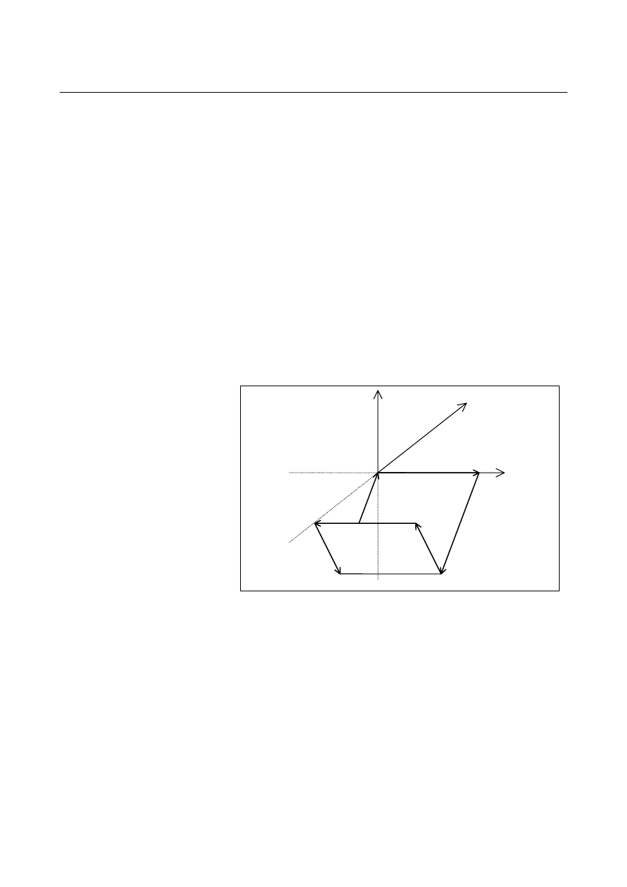
Fig. 22.5.1.1 (j)    Conceptual diagram 


B-63944EN/03

 PROGRAMMING 

22.5-AXIS MACHINING FUNCTION


- 909 - 


Va

Vb

46

°


45

°


Va: Tool vector when A=-46 
Vb: Tool vector when A=45 
A:    End point of N3 
B:    End point of N4 
C:    End point of N6 


Fig. 22.5.1.1 (k)    Tool vector 


e3 

e2 

A’ 

C’ 

B’ 

V1

V2

A’:    Point A projected onto the compensation plane 
B’:    Point B projected onto the compensation plane 
C’:  Point C projected onto the compensation plane 


Fig. 22.5.1.1 (l)    Compensation vector at the end point (point B) of N4 (in 

the compensation plane) 

 
The movement direction of A'B' is opposite to that of B'C', so two 
compensation vectors V1 and V2 are produced at point B' (the end 
point of N4).    In such a case, there is a possibility of overcutting, so 
an alarm PS0041 is issued at N4. 
 
<1>  Conditions for issuing the interference alarm 
 

Suppose that a move command for a rotary axis makes the tool 
vector change significantly from one block to another.    In this 
case, an interference alarm is assumed because compensation 
vectors are regarded as being generated in wrong directions when 
the path angle difference in the compensation plane is large, even 
though the angle difference between the directions of 
compensation vectors to be generated by those blocks is small. 


Here, the compensation plane is perpendicular to the tool 
direction (Va in the figure below) of the first of the two blocks. 


Specifically, the conditions listed below are used for issuing the 
alarm. 

22.5-AXIS MACHINING FUNCTION

 PROGRAMMING 

B-63944EN/03


- 910 - 

Ua: Vector AB 
Ub: Vector BC 
Va: Tool vector between A and B 
Vb: Tool vector between B and C 
Wa: Va 

×

 Ua 

Wb: Vb 

×

 Ub 

(Here, 

×

 represents an outer product operator.) 

Va

Vb

Wa

Wb

Ua 

Ub


Fig. 22.5.1.1 (m)    Conceptual diagram 


A’:    Point A projected onto the compensation plane 
B’:    Point B projected onto the compensation plane 
C’:  Point C projected onto the compensation plane 
Ra:  Vector A’B’ 
Rb:  Vector B’C’ 

e3 

e2 

A’ 

C’ 

B’ 

Ra

Rb


Fig. 22.5.1.1 (n)    Programmed path before and after the end point (point 

B) of N4 (in the compensation plane) 


When all the following conditions are satisfied, an alarm 
PS0041) is issued: 
(1)  The tool vector changes significantly. 

α

:  Angle for determination set in parameter No. 19635 

(The default is 45

°

.) 

 (Va,Vb) 

 cos(

α

)(where, (Va,Vb) means an inner product.) 

(2)  The difference between the directions of the compensation 

vectors to be generated is small. 
Wa: Direction of a compensation vector to be generated by 

block AB 

Wb: Direction of a compensation vector to be generated by 

block BC 


Wa = Va 

×

 Ua 


Wb = Vb 

×

 Ub 

 (Wa,Wb) 

 0 

B-63944EN/03

 PROGRAMMING 

22.5-AXIS MACHINING FUNCTION


- 911 - 

(3)  The path angle difference in the compensation plane is 

large. 


(Ra,Rb) < 0 


<2>  Suppressing the issue of the alarm with a Q command 
 

By inserting a Q command into a block that resulted in the alarm, 
the issue of the alarm can be suppressed. 
(1) Q1 

command 


By inserting a Q1 command, a perpendicular vector is 
generated. 


Example:    N4 Y-200 Z-200 Q1 


At B', a vector (V) perpendicular to A'B' is generated. 

e3 

e2 

A’ 

C’ 

B’ 


Fig. 22.5.1.1 (o)    Q1 command 


A perpendicular vector can also be generated by specifying 
G41.2 or G42.1 in the next block as follows: 


Example:    N6 G41.2 Y-400 Z0 

(2) Q2 

command 


With a program specifying a linear-to-linear connection, up 
to two compensation vectors are generated.  In this case, 
the second vector is deleted by inserting a Q2 command. 


The Q2 command has no effect on circular interpolation. 


Example:    N4 Y-200 Z-200 Q2 

The second vector (V2) is deleted, and only V1 is used as a compensation vector. 

e3 

e2 

A’ 

C’ 

B’ 

V1


Fig. 22.5.1.1 (p)    Q2 command 


22.5-AXIS MACHINING FUNCTION

 PROGRAMMING 

B-63944EN/03


- 912 - 

(3) Q3 

command 


By inserting a Q3 command, the issue of the alarm can be 
suppressed. 


Example:    N4 Y-200 Z-200 Q3 


The two vectors (V1 and V2) are not deleted. 

e3 

e2 

A’ 

C’ 

B’ 

V1

V2


Fig. 22.5.1.1 (q)    Q3 command 


 - Others 

When the tool movement changes linear to circular (helical), circular 
(helical) to linear, or circular (helical) to circular (helical), the start, 
end, and center points of a circular (helical) movement are projected 
on the compensation plane that is perpendicular to the tool axis, and a 
compensation vector is calculated in the plane.    The obtained vector 
is added to the originally specified position to create a position to be 
specified.    Then, the tool is moved linearly or circularly (helically) to 
the created position. 


Z

Y

Tool

Tool axis

Start point

End point

Tool 

Tool center path created in the compensation plane

(Compensation plane = XY plane) 

Compensation vector

created in the   

compensation plane 

Actual 

compensation 

vector 

Move command

Projected


Fig. 22.5.1.1 (r)    Operation during compensation 


B-63944EN/03

 PROGRAMMING 

22.5-AXIS MACHINING FUNCTION


- 913 - 

  - Angle of the rotary axis for type 2 (when the movement range is not specified) 

When the direction of the tool is specified by I, J, K, Q for type 2, 
more than two pairs of "computed angles" of the rotary axes usually 
exist. 
The "computed angle" is the candidate angle at which the rotary axis 
is to be controlled in the specified tool axis direction. 
The "output angle" is determined from the "computed angle" based on 
the "output judgment conditions" described below. 
The following descriptions assume that there is no movement range 
specification (parameter No.19741 - No.19744 = 0). 

Tool rotation type or table rotation type machine 

<1>  The "output angles" are represented by the computed rotary axis 

angle pair whose master axis (first rotary axis) moving angle is 
smaller. 


 When the master axis moving angle is the same 


<2>  The "output angles" are represented by the computed rotary axis 

angle pair whose slave axis (second rotary axis) moving angle is 
smaller. 


 When the slave axis moving angle is the same 


<3>  The "output angles" are represented by the computed rotary axis 

angle pair whose master axis (first rotary axis) angle is nearer to 0 
degree (multiple of 360 degrees). 


 When the master axis angle is equally near to 0 degree


<4>  The "output angles" are represented by the computed rotary axis 

angle pair whose slave axis (second rotary axis) angle is nearer to 0 
degree (multiple of 360 degrees). 

Composite type machine 

<1>  The "output angles" are represented by the computed rotary axis 

angle pair whose table (second rotary axis) moving angle is smaller. 


 When the table moving angle is the same 


<2>  The "output angles" are represented by the computed rotary axis 

angle pair whose tool (first rotary axis) moving angle is smaller. 


 When the tool moving angle is the same 


<3>  The "output angles" are represented by the computed rotary axis 

angle pair whose table (second rotary axis) angle is nearer to 0 
degree (multiple of 360 degrees). 


 When the table angle is equally near to 0 degree 


<4>  The "output angles" are represented by the computed rotary axis 

angle pair whose tool (first rotary axis) angle is nearer to 0 degree 
(multiple of 360 degrees). 

Fig. 22.5.1.1 (s)  Output judgment conditions 

22.5-AXIS MACHINING FUNCTION

 PROGRAMMING 

B-63944EN/03


- 914 - 

 
The process of judging whether the moving angle is smaller or larger 
as the output judgement condition is called "movement judgement." 
When bit 5 (PRI) of parameter No.19608 is 1, the movement 
judgements for the first rotary axis and second rotary axis are made in 
reverse order. 
 
The "movement judgement" process is explained below. 
When the "computed angle" is within the range between 0 and 360 
degrees, it is called the "basic computed angle." 
Usually, two pairs of "basic computed angles" exist. 
For example, assume that a tool rotation type or table rotation type 
machine has rotary axis A (master) and rotary axis B (slave) and that 
there are two pairs of basic computed angles as follows: 
(A 

θ

1 degree; B 

φ

1 degree) 

(A 

θ

2 degrees; B 

φ

2 degrees)   where 

θ


θ

2. 

The "computed angle" is obtained from either of the following 
expressions:  "basic computed angle" + 360 degrees 

×

 N or "basic 

computed angle" - 360 degrees 

×

 N. 

The current position of rotary axis A (master) is PA, and that of rotary 
axis B (slave) is 0 degree. 
Based on the PA angle, the "movement judgement" process is done as 
follows (when bit 5 (PRI) of parameter No.19608 is 0). 
 

  Computed angle A

-360 

×

 (N + 1) degrees

θ

1 - 360 

×

 N

-360 

×

 N degrees

θ

2 - 360 

×

 N

θ

2 - 360 

×

 (N + 1)

θ

1 - 360 

×

 (N - 1)

(*1)

0 degree

360 degrees

θ

2 - 360

θ

1

θ

2

θ

1 + 360

(*2)

360 

×

 (N + 1) degrees

θ

1 + 360 

×

 N

360 

×

 N degrees

θ

2 + 360 

×

 N

θ

2 + 360 

×

 (N - 1)

θ

1 + 360 

×

 (N + 1)

(*3)


Fig. 22.5.1.1 (t)  Movement judgment 


B-63944EN/03

 PROGRAMMING 

22.5-AXIS MACHINING FUNCTION


- 915 - 

When the PA angle is (*1): 
The output angle is:    (A 

θ

2 - 360 × (N + 1) degrees; B 

φ

2 degrees). 

Namely, 

θ

2 - 360 × (N + 1) degrees is adopted that is nearer to the 

computed angle of A, and 

φ

2, which is the same group as 

θ

2, is 

adopted as the computed angle of B. 
 
When the PA angle is (*2): 
The output angle is:    (A 

θ

1 degrees; B 

φ

1 degrees). 

Namely, 

θ

1 degrees is adopted that is nearer to the computed angle of 

A, and 

φ

1, which is the same group as 

θ

1, is adopted as the computed 

angle of B. 
 
When the PA angle is (*3): 
The output angle is:    (A 

θ

2 + 360 × N degrees; B 

φ

2 degrees). 

Namely, 

θ

2 + 360 × N degrees is adopted that is nearer to the 

computed angle of A, and 

φ

2, which is the same group as 

θ

2, is 

adopted as the computed angle of B. 
 
When the moving angle of rotary axis A (master) is the same, a 
"movement judgement" is made for rotary axis B (slave) according to 
the "output judgment conditions." 
If the "output angle" of rotary axis A is determined by the "movement 
judgement" for rotary axis A, the computed angle representing the 
"smaller moving angle" is adopted as the "output angle" of rotary axis 
B. 
Similarly, if the "output angle" of rotary axis B is determined by the 
"movement judgement" for rotary axis B, the computed angle 
representing the "smaller moving angle" is adopted as the "output 
angle" of rotary axis A. 
 
The "output angle" is explained below using a tool rotation type 
machine as an example. 
This example illustrates a machine having a "BC type tool axis Z." 
 

    BC type tool axis Z

X

Y

Z

C-axis:

First rotation axis
(master)

B-axis: Second rotation axis

(slave)


Fig. 22.5.1.1 (u)    BC type tool axis Z 

 
The following two pairs of "computed basic angles" exist that direct 
the tool axis toward the +X-axis direction. 
(B 90 degrees; C 180 degrees) 
(B 270 degrees; C 0 degree) 


Content      ..     117      118      119      120     ..