FANUC Series 30i/300i/300is-MODEL A. Machining Center System. User's manual - page 118
 

  Index      Manuals     FANUC Series 30i/300i/300is-MODEL A. Machining Center System. User's manual (B-63944EN/03)


Search            copyright infringement  


Content      ..     116      117      118      119     ..


FANUC Series 30i/300i/300is-MODEL A. Machining Center System. User's manual - page 118


22.5-AXIS MACHINING FUNCTION

 PROGRAMMING 

B-63944EN/03


- 900 - 

22.5.1 

Cutter Compensation in Tool Rotation Type Machine 


Overview 

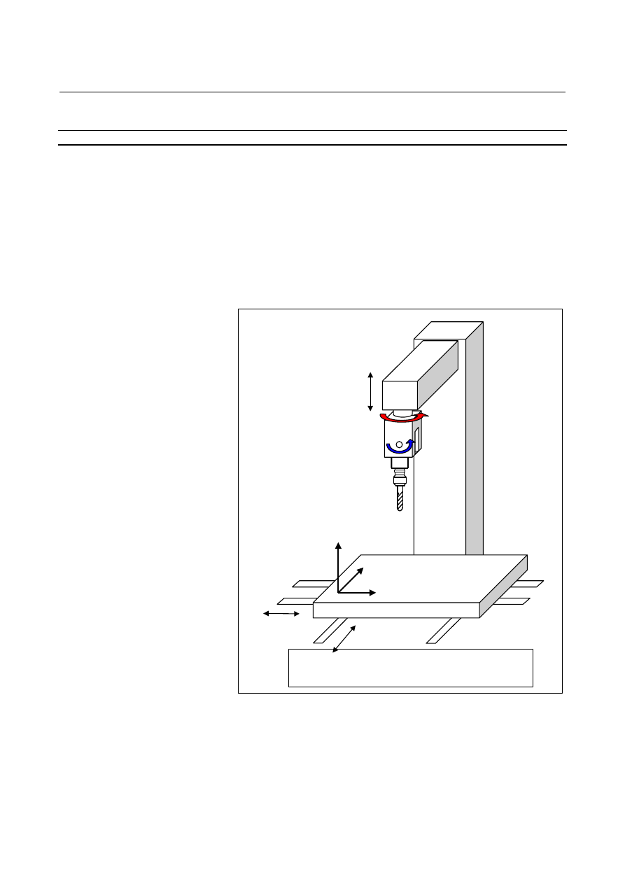
In a 5-axis machine having two tool rotation axes as shown in Fig. 
22.5.1 (a), this function can perform cutter compensation. 
Shown below is a 5-axis machine that has tool rotation axis B on the 
Y-axis and tool rotation axis C on the Z-axis. 
This machine configuration is used as a sample configuration in the 
following explanation unless otherwise noted. 
 
Cutter compensation in tool rotation machines is classified into two 
types according to the way of machining:  tool side offset and 
leading edge offset. 
 

Workpiece coordinate system:  A coordinate
system used for creating programs

B

C

Z

Y

X

X

Y

Z Workpiece coordinate

system


Fig. 22.5.1 (a)    Machine having two tool rotation axes 


B-63944EN/03

 PROGRAMMING 

22.5-AXIS MACHINING FUNCTION


- 901 - 

22.5.1.1 

Tool side offset 


Overview 

This type of cutter compensation performs three-dimensional 
compensation in a plane (compensation plane) perpendicular to the 
tool vector. 
 

Compensation
plane

Y

Z

X

Tool vector

Cutter compensation
amount

Tool center path
(path after
compensation)

Programmed path
(path before compensation)

Cutter compensation vector


Fig. 22.5.1.1 (a)    Tool side offset 


Format 
  - Tool side offset (type 1) 

G41.2 (or G42.2) 

IP

_ D_ ; 

IP

_ ; 

      : 

G41.2: Cutter compensation left (group 07) 
G42.2: Cutter compensation right (group 07) 

IP

_: 

Value specified for axis movement (including rotary 
axis) 

D_: 

Code specifying the cutter compensation amount (1 
to 3 digits) 


  - Tool side offset (type 2) 

G41.6 (or G42.6) 

IP

_ I_ J_ K_ D_ Q_ ; 

IP

_ I_ J_ K_ ; 

      : 

G41.6: Cutter compensation left (group 07) 
G42.6: Cutter compensation right (group 07) 

IP

_: 

Value specified for axis movement (without rotary 
axis) 

D_: 

Code specifying the cutter compensation amount (1 
to 3 digits) 

Q_: 

Tool’s angle of gradient (in degrees) 

I_ J_ K_:  Tool axis direction at the block end point as 

viewed from the programming coordinate system


22.5-AXIS MACHINING FUNCTION

 PROGRAMMING 

B-63944EN/03


- 902 - 

For type 2, do not specify a rotation axis but specify the direction at 
the tool end point as viewed from the programming coordinate system 
(workpiece coordinate system), with I, J, and K.  Specifying a 
rotation axis causes alarm PS5460 to be generated. 
 

NOTE 


When a movement perpendicular to the next 
movement (bit 1 (SUV) of parameter No. 5003 is 
set to 1) is specified as the operation performed 
at the time of startup or cancellation, a move 
command such as X_ Y_ Z_ must not be 
specified in the G41.2 and G42.2 block. 

 
The following are the notes on type 2. 

NOTE 

1  If one or two of I, J, and K are omitted, the omitted 

ones of I, J, and K are assumed to be 0. 

2  In a block in which all of I, J, and K are omitted, 

the values of I, J, and K in the previous block are 
used. 

3  If there is only one rotation axis (a hypothetical 

axis is used), type 2 cannot be used.    In this 
case, if an attempt is made to issue G41.6/G42.6, 
alarm PS5460 is generated. 

4  If using the rotation axis rollover function or rotary 

axis control function, specify 360 degrees in 
parameter No. 1260 (mount of travel per rotation 
about the rotation axis). 

5  Only tool side offset provides type 2 commands.   

Leading edge offset, described later, does not 
provide type 2 commands. 


  - Canceling the tool side offset 

G40 

IP

_ ;   

G40:  Cancellation of cutter compensation (group 07) 

IP

_:  Value specified for axis movement 


B-63944EN/03

 PROGRAMMING 

22.5-AXIS MACHINING FUNCTION


- 903 - 

Explanation 
  - Tool’s angle of gradient in type 2 

For type 2 of 3-dimensional cutter compensation, the tool's angle of 
gradient can be specified with address Q in a G41.6/G42.6 command 
block.    The tool's angle of gradient refers to the angle by which the 
tool direction to be assumed when machining is actually performed is 
inclined from the direction specified with (I, J, K) toward the traveling 
direction on the plane formed by the tool direction specified with (I, J, 
K) and the traveling direction in the programming coordinate system.   
(See Fig. 22.5.1.1 (b).) 
Because in general, the normal direction of the machining surface is 
specified with (I, J, K), if it is desired to incline the tool direction to be 
assumed when machining is actually performed from the normal 
direction toward the traveling direction, correction may be performed 
with a Q command. 
If the direction specified with (I, J, K) matches the tool direction to be 
assumed when machining is actually performed, no Q command is 
necessary. 


Tool direction to be assumed when 
machining is actually performed 

(Plane perpendicular to the "tool direction to be 
assumed when machining is actually performed") 

Tool direction 
specified with (I, J, K)

Traveling 
direction of 
machining

Tool's angle of gradient (Q) 

Compensation plane 

Tool center path 
(path after compensation)

Programmed path 
(path before compensation)

Cutter 
compensation 
vector 


Fig. 22.5.1.1 (b)    Tool's angle of gradient in type 2 

 
(Example) 
 

To perform machining by inclining the tool's traveling direction 
twice, issue a command such as the following: 


G41.6 I_ J_ K_ H_ Q2.0 


22.5-AXIS MACHINING FUNCTION

 PROGRAMMING 

B-63944EN/03


- 904 - 

  - Operation at startup and cancellation 

<1> Type A 
 

The tool is moved in the same way as for cutter compensation as 
shown below. 


Tool

G41.2 

G40 

:  Tool center path 
:  Programmed path 

Operation in linear interpolation 


:  Tool center path 
:  Programmed path

Tool

G42.2

G40 

Operation in circular interpolation 


Fig. 22.5.1.1 (c)    Operation at startup and cancellation (type A) 

 
When the G40 block contains no movement command, type C 
cancellation is performed (see <3> Type C below).   
 
<2> Type B 
 

The tool is moved in the same way as for cutter compensation as 
shown below. 


Tool

G41.2 

G40 

:  Tool center path
:  Programmed path 

Operation in linear interpolation 


:  Tool center path 
:  Programmed path 

Tool 

G42.2

G40 

Operation in circular interpolation 


Fig. 22.5.1.1 (d)    Operation at startup and cancellation (type B) 

B-63944EN/03

 PROGRAMMING 

22.5-AXIS MACHINING FUNCTION


- 905 - 

 
When the G40 block contains no movement command, type C 
cancellation is performed (see <3> Type C below).   
 
<3> Type C 
 

When G41.2, G42.2, or G40 is specified as shown below, a linear 
block specifying movement by the amount of cutter 
compensation in the direction orthogonal to the movement 
direction of the block following startup or the block preceding 
cancellation is inserted. 

Tool

G41.2

G40

:  Tool center path
:  Programmed path

Operation in linear interpolation


:  Tool center path
:  Programmed path

Tool

G42.2

G40

Operation in circular interpolation


Fig. 22.5.1.1 (e)    Operation at startup and cancellation (type C) 


NOTE 


For type C (bit 1 (SUV) of parameter No. 5003 is 
1), the following conditions need to be satisfied 
during startup and cancellation. 

1  A block specifying G40, G41.2, or G42.2 must 

be in the G00 or G01 mode. 

2  A block specifying G40, G41.2, or G42.2 must 

contain no move command. 

3  The block next to a block specifying G41.2 or 

G42.2 must contain move command G00, G01, 
G02, or G03. 


22.5-AXIS MACHINING FUNCTION

 PROGRAMMING 

B-63944EN/03


- 906 - 

  - Operation during compensation 

Operations such as change of the offset direction and offset value, 
retention of a vector, and interference checks are performed in the 
same way as for cutter compensation.  However, G39 (corner 
rounding) cannot be specified.    So, note the following: 

 
<1>  When the tool center path goes outside the programmed path at a 

corner, a linear movement takes place at the corner without 
inserting an arc.  When the tool center path goes inside the 
programmed path, nothing is inserted. 


:  Tool center path 

:  Programmed path 

Example <1>-1 
Going outside    of corner at 
acute angle 

Example <1>-2 
Going inside of corner 

Linear block inserted 

Tool 

Tool 

Workpiece

Workpiece

:

  Tool compensation

   amount 

Nothing inserted 


Fig. 22.5.1.1 (f)  Operation during compensation <1>-1 and <1>-2 


In the above examples, the terms "inside" and "outside" denote 
how the tool center path is positioned with respect to the 
programmed path.  In the figure below, example <1>-3 shows 
the same relationship between the tool center path and 
programmed path as example <1>-1 and indicates that the tool 
center path is outside the programmed path; example <1>-4 
shows the same relationship as example <1>-2 and indicates that 
the tool center path is inside the programmed path. 

:  Tool center path 
: Programmed path

Example <1>-3

Example <1>-4 

Actual 
tool 

Reference 
tool 

Actual 
tool 

Reference 
tool 

Workpiece

Workpiec

: Tool compensation 

amount 


Fig. 22.5.1.1 (g)    Operation during compensation <1>-3 and <1>-4 


B-63944EN/03

 PROGRAMMING 

22.5-AXIS MACHINING FUNCTION


- 907 - 

<2> When the tool moves at a corner, the feedrate of the previous 

block is used if the corner is positioned before a single-block 
stop point; if the corner is after a single-block stop point, the 
feedrate of the next block is used. 


:  Tool center path 
:  Programmed path 

Example <2>-1 

F100 

Tool 

Program <2>-1 

 : 

N1 G90 G41.2 Xp Yp Zp Bp Cp D1 ;

N2 G01 Xq Yq Zq F100 ; 

N3 Xr Yr Zr F200 ; 

 : 

N2

N3

P' 

Q1'

R' 

Q2' (single-block stop point) 


Fig. 22.5.1.1 (h)    Operation during compensation <2> 


In the above example, the single-block stop point of N2 is Q2', so 
the feedrates along paths P'-Q1' and Q1'-Q2' are both F100. 

 
<3> When a command that makes the tool retrace the path of the 

previous block is specified, the tool path can match the locus of 
the previous block by changing the G code to change the offset 
direction.    If the G code is left unchanged, the operation shown 
in example <3>-2 results: 


:  Tool center path 

:  Programmed path 

Example <3>-1 
When changing G41.2 to G42.2 
(G41.2 mode) 

G91 G01 X100.0 
G42.2 X-100.0 

Example <3>-2 
When leaving G code unchanged
(G41.2 mode) 

G91 G01 X100.0 
X-100.0


Fig. 22.5.1.1 (i)    Operation during compensation <3> 


Content      ..     116      117      118      119     ..