FANUC Series 30i/300i/300is-MODEL A. Machining Center System. User's manual - page 108
 

  Index      Manuals     FANUC Series 30i/300i/300is-MODEL A. Machining Center System. User's manual (B-63944EN/03)


Search            copyright infringement  


Content      ..     106      107      108      109     ..


FANUC Series 30i/300i/300is-MODEL A. Machining Center System. User's manual - page 108


22.5-AXIS MACHINING FUNCTION

 PROGRAMMING 

B-63944EN/03


- 820 - 

C-axis rotates, with C
being 240 degrees.

(C 120.0)

(B 60.0)

(B 60.0)

(C 240.0)

(C 360.0)

(B 0)

(C-axis rotates, with C being
360 degrees.)

N80 block

N90 block

N100 block

(C 240.0)

(B 60.0)

(B 60.0)

Y"

X"

Y"

X"

X'

Y'

Y'

X'

X' X"

Y'

Y"


Detailed diagram of each block (2) 


B-63944EN/03

 PROGRAMMING 

22.5-AXIS MACHINING FUNCTION


- 821 - 

  - When circular interpolation is performed during tool center point control 

In this example, one of the three sides


of an equilateral triangle, each 

being 100 mm long side, is specified as a straight line and the other 
two are specified as arcs, and each side is cut at B-axis angles of -60,   
-45 to -30, and -30 degrees, respectively.    (For the X-axis, its radius 
is specified.) 
Example) 
The program sample given below assumes that the table-fixed 
coordinate system is used as the programming coordinate system.  
When the workpiece coordinate system is used as the programming 
coordinate system (when bit 5 (WKP) of parameter No.19696 is set to 
1), the same shape can be obtained by specifying the values shown in 
parentheses. 
 

N001 T0000 ; 

Cancels the tool offset. 

N002 G54 ; 

Selects the workpiece coordinate system. 

N003 G90 X50.0 Y-70.0 Z300.0 B-90.0 C0.0 ;    Moves to the initial position.
     

The tool tip faces the Z- direction at B-axis 
angle of -90 degrees. 

N020 G01 G43.4 H01 

Starts tool center point control. 

N021 Z20.0 ; 

Moves to the approaching position. 

N022 X28.868 Y-50.0 Z10.0 B-60.0 ;  The Z-axis height on the machining 

plane is 10.0. 

N031 Y50.0 ; 
N032 B-45.0 C90.0 ; 
(N032 X50.0 Y-28.868 B-45.0 C90.0 ;)     
N033 G17 G03 X-57.735 Y0.0 J-100.0 B-30.0 C150.0 ; 
     

Moves X and Y while operating both B- 
and C-axes. 

(N033 G17 G03 X50.0 Y28.868 I-100.0 B-30.0 C150.0 ;)     
N034 G01 B-30.0 C210.0 ; 
(N034 G01 X50.0 Y-28.867 B-30.0 C210.0 ;)     
N035 G03 X28.868 Y-50.0 I86.603 J50.0 C270.0 ; 
(N035 G03 X50.0 Y28.868 I-100.0 C270.0 ;)     
N041 G01 X50.0 Y-70.0 Z20.0 B-90.0 C360.0 ; 


X, Y, and Z are approaching positions. 


The rotary axes move to their original 
positions. 

N050 G49 ; 

Cancels tool center point control. 

N051 Z300.0 ;   

Moves the Z-axis to its initial position. 


22.5-AXIS MACHINING FUNCTION

 PROGRAMMING 

B-63944EN/03


- 822 - 

C-axis

Center of the C-

axis rotation

X

Y

Z

Z-axis

Y-axis

X-axis

B-axis

Center of the B-axis

rotation

Tool center

point

G54 workpiece
coordinate system


Machine configuration for the circular interpolation example 

 
The following figure illustrates the relative positional relationship 
between the workpiece and the tool head and their positions, as seen 
from the +Z direction.    The X and Y coordinate values shown in the 
figure are those on the table-fixed programming coordinate system 
(which rotates as the C-axis turns). 


(X 50.0, Y -70.0, Z 300.0, B -90.0)

(X 28.868, Y -50.0)

(B -60.0)

(B -60.0)

(B -45.0)

(X 28.868, Y 50.0)

(X -57.735, Y 0.0)

(C 0.0)

(C 90.0)

(C 150.0)

(B -30.0)

(B -30.0)

(B -30.0)

Y

X

(C 210.0)

(C 270.0

)

    Behavior as seen from the table-fixed programming coordinate system


Illustration of the example 


B-63944EN/03

 PROGRAMMING 

22.5-AXIS MACHINING FUNCTION


- 823 - 

X

Y

  [Up to N031]

Y

X

Behavior of the tool

center point

B -60

Behavior of the control point (machine

coordinate 

system)

B -90

X

Y

 [N032]

B -45

C 90

B -60

[N034]

B -30

B -30

Y

X

[N033]

B -45

B -30

C 150

Head path relative
to the workpiece

Apparent head path

C 210

B -30

[N035]

B -30

X

Y

C 270

X

Y

[N041 and later]

B -30

B -90

Head path

relative to the

workpiece

Apparent head path

C 360

Apparent head path

Head path relative to
the workpiece


Detailed diagram of each block 


22.5-AXIS MACHINING FUNCTION

 PROGRAMMING 

B-63944EN/03


- 824 - 

Limitation 
 - Manual intervention 

Manual intervention is impossible during tool center point control. 
If manual intervention is performed, alarm PS5421 is issued when 
automatic operation is started later. 
 

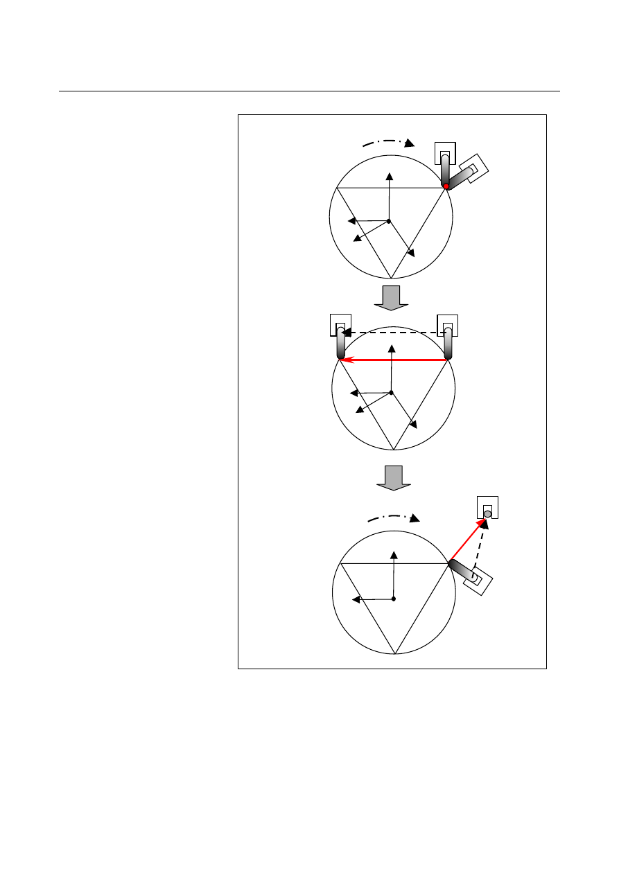
  - Hypothetical axis of a table rotation axis 

When a table rotation axis is set as a hypothetical axis, tool center 
point control is performed on the assumption that the table rotation 
axis is at 0 degrees. 
 

 - Look-ahead pre-interpolation acceleration/deceleration 

When the tool center point control mode is set, look-ahead 
acceleration/deceleration before interpolation is automatically enabled.   
Set the parameter for look-ahead acceleration/deceleration before 
interpolation.    If the parameter is not set correctly, alarm PS5420 is 
issued. 

 Example: 


Interpolation 
path 

Path of tool 
center point


In the above example, the feedrate is controlled so that the tool center 
point moves at a specified feedrate, so the feedrate on the interpolation 
path is equal to or higher than the specified feedrate.    At this time, 
look-ahead acceleration/deceleration before interpolation allows the 
feedrate to be clamped so that the feedrate on the interpolation path 
does not exceed the maximum cutting feedrate or maximum rapid 
traverse rate. 
 

  - Deceleration at a corner 

Under tool center point control, the controlled point may move along a 
curve even if a straight-line command is issued.  Some commands 
may cause a corner movement. 
When AI contour control is not used, a shock can be applied to the 
machine at a corner. 
So, it is recommended to use AI contour control as well and set an 
allowable speed difference at a corner (parameter No. 1783) and an 
allowable acceleration rate (parameter No. 1660, No. 1737). 
 

B-63944EN/03

 PROGRAMMING 

22.5-AXIS MACHINING FUNCTION


- 825 - 

  - 3-dimensional cutter compensation 

3-dimensional cutter compensation and tool center point control can 
be used at the same time. 
For restrictions in such a case, see "Restrictions" of 3-dimensional 
cutter compensation. 
 

  - Programmable mirror image 

Note the following points when making


a programmable mirror 

image: 


In the case of tool center point control of type 1 


Mirroring the linear axis alone does not create a mirror image for 
the rotary axis.    To make the direction of the tool symmetrical, 
it is necessary to make a mirror image for the rotary axis as well. 


In the case of tool center point control of type 2 


When bit 6 (MIR) of parameter No.19608 is set to 0, mirroring 
the linear axis alone does not create a mirror image for I, J, K.   
Note that the inclination direction specified by Q is the 
movement direction of the tool center point after mirroring. 


When bit 6 (MIR) of parameter No.19608 is set to 1, mirroring 
the linear axis automatically creates a mirror image for I, J, K. 


A mirror image cannot be put on the rotary axis directly. 


 - Scaling 

Do not apply scaling to a rotary axis. 
 

  - Machine coordinate system command 

During tool center point control, the machine coordinate system 
command (G53) cannot be used. 
However, G53 can be specified singly to suppress look-ahead 
operation. 
 

  - Stored limit check before move 

During tool center point control, stored limit check before move is 
disabled. 
 

 - Type 2 

When a type 2 command (G43.5 command) is specified on a machine 
of table rotation type or composite type (parameter No. 19680 = 12 or 
21), the table coordinate system needs to be set as the programming 
coordinate system (by setting bit 5 (WKP) of parameter No. 19696 to 
0).    If type 2 is specified with a workpiece coordinate system set as 
the programming coordinate system, alarm PS5459 is issued. 
 

  - Specifiable G codes


The G codes that can be specified in the tool center point control 
mode are listed below. 
Specifying a G code other than these codes results in alarm PS5421. 

 Positioning 

(G00) 


Linear interpolation (G01) 


Circular interpolation / helical interpolation (G02/G03) 

 Dwell 

(G04) 

22.5-AXIS MACHINING FUNCTION

 PROGRAMMING 

B-63944EN/03


- 826 - 


Exact stop (G09) 


Programmable data input (G10) 


Tool retract and recover (G10.6) 


Programmable data input mode cancel (G11) 


Plane selection (G17/G18/G19) 


Tool radius compensation cancel (G40) 


3-dimensional cutter compensation 
(G41.2/G42.2/G41.4/G42.4/G41.5/G42.5) 


Tool length compensation cancel (G49) 

 Scaling 

(G50/G51) 


Programmable mirror image (G50.1/G51.1) 


Machine coordinate system command (G53) specified singly 

 Cutting 

mode(G64) 


Macro call (G65) 


Macro modal call A (G66) 


Macro modal call B (G66.1) 


Macro modal call A/B cancel (G67) 


Absolute programming (G90) 


Incremental programming (G91) 


Canned cycle : return to initial level (G98) 


Canned cycle : return to R point level (G99) 


  - Modal G codes that allow specification of tool center point control


Tool center point control can be specified in the modal G code states 
listed below. 
Tool center point control cannot be specified in a modal state other 
than these. 
 

  Modal G codes included in "Specifiable G codes" described 

previously 


Polar coordinate interpolation mode cancel (G13.1) 


Polar coordinates command cancel (G15) 


Input in inch (G20 (G70)) 


Input in mm (G21 (G71)) 


Polygon turning cancel (G50.2) 


Workpiece coordinate system setting (G54 to G59) 


Canned cycle cancel (G80) 


Constant surface speed control cancel (G97) 


M


Coordinate system rotation cancel or 3-dimensional coordinate 
conversion mode off (G69) 


Feed per minute (G94) 


Polar coordinate interpolation mode cancel (G113) 


B-63944EN/03

 PROGRAMMING 

22.5-AXIS MACHINING FUNCTION


- 827 - 

T


Mirror image for double turret off/balanced cutting mode cancel 
(G69) 


Coordinate system rotation cancel or 3-dimensional coordinate 
conversion mode off (G69.1) 


Feed per minute (G98 (G94)) 


-  Specification of axes not relating to tool center point control


Axes not relating to tool center point control cannot be specified.    If 
such an axis is specified, alarm PS5421 is issued. 
 

-  Linear axes under tool center point control


The basic three axes set in parameter No. 1022 are regarded as the 
three linear axes for tool center point control.  Axes parallel to the 
basic three axes cannot be used as the linear axes for tool center point 
control. 
If the basic three axes are not set in parameter No. 1022, alarm 
PS5459 is issued. 
 

T


-  Extended tool selection 

When tool center point control is used with a lathe system, the tool 
change method needs to be ATC type (bit 3 (TCT) of parameter No. 
5040 = 1). 
In this case, only the value set in "Z" on the tool compensation 
memory screen is used as a tool length compensation amount.  Set 
values such as "X", "R", and "Y" axis offset values are not used. 


Content      ..     106      107      108      109     ..