FANUC Series 30i/300i/300is-MODEL A. Machining Center System. User's manual - page 100
21.AXIS CONTROL FUNCTIONS
PROGRAMMING
B-63944EN/03
- 756 -
21.7.4.2
Description of commands compatible with those for a
hobbing machine (G80, G81)
A command compatible with that for a hobbing machine can be used
as a synchronization command.
Usually, a hobbing machine performs machining by synchronizing the
workpiece axis (usually, the C-axis) to the hobbing axis (spindle).
If there are two synchronization sets with the EGB, which
synchronization set to start with this specification method can be
specified with parameter No. 7710.
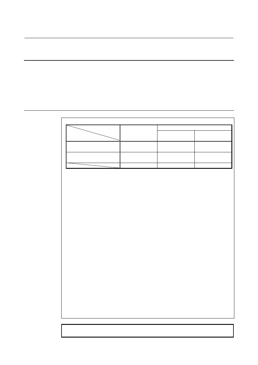
Format
Parameter EFX(No.7731#0)=1
Parameter EFX
(No.7731#0)=0
Parameter HBR
(No.7731#5)=1
Parameter HBR
(No.7731#5)=0
Start of synchronization
G81 T
_
( L
_
)
( Q
_
P
_
) ;
G81.4 R
_
( L
_
)
( Q
_
P
_
) ;
G81.4 T
_
( L
_
)
( Q
_
P
_
) ;
Cancellation of
synchronization
G80 ;
G80.4 ;
G80.4 ;
(*1) (*2) (*3)
T(or R) : Number of teeth (Specifiable range: 1 to 1000)
L : Number of hob threads (Specifiable range: -200 to +200)
The sign of L determines the direction of rotation for the workpiece
axis.
When L is positive, the direction of rotation for the workpiece axis
is positive (+ direction).
When L is negative, the direction of rotation for the workpiece axis
is negative (- direction).
When L is 0, it follows the setting of bit 3 (LZR) of parameter
No.7701.
If L is not specified, the number of hob threads is assumed 1.
Q : Module or diametral pitch
Specify a module in the case of metric input.
(Unit: 0.00001mm, Specifiable range: 0.01 to 25.0mm)
Specify a diametral pitch in the case of inch input.
(Unit: 0.00001inch
-1
, Specifiable range: 0.01 to 254.0 inch
-1
)
P : Gear helix angle
(Unit: 0.0001deg, Specifiable range: -90.0 to 90.0deg)
*1 Use it for machining centers.
*2 Use it for lathes.
*3 Use it for machining centers.
This format enables specification of the same G codes as those
for lathes.
*4 When specifying Q and P, the user can use a decimal point.
NOTE
Specify G81, G80, G81.4, and G80.4 in a single block.