FANUC Series 30i/300i/300is-MODEL A. Machining Center System. User's manual - page 99
 

  Index      Manuals     FANUC Series 30i/300i/300is-MODEL A. Machining Center System. User's manual (B-63944EN/03)


Search            copyright infringement  


Content      ..     97      98      99      100     ..


FANUC Series 30i/300i/300is-MODEL A. Machining Center System. User's manual - page 99


21.AXIS CONTROL FUNCTIONS

 PROGRAMMING 

B-63944EN/03


- 748 - 

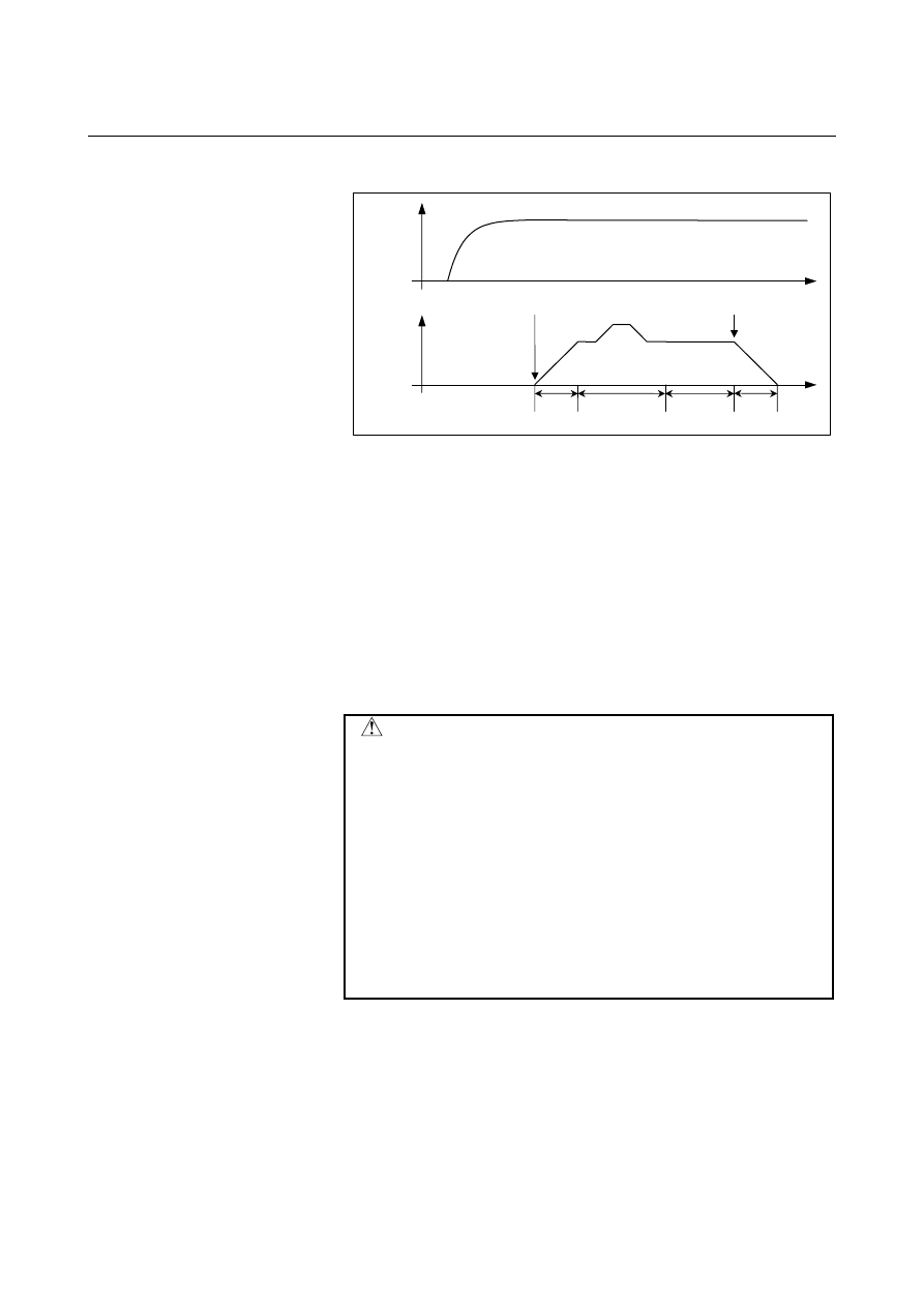
 - Acceleration/deceleration plus automatic phase synchronization type 

Automatic phase 

synchronization 

Synchronization 

cancellation command

Synchronization 

start command

Workpiece-

axis speed

Synchronization 

state 

Acceleration

Deceleration

Spindle 

speed


1.  Move the workpiece axis to the position that corresponds to that 

of the one-rotation signal of the spindle.   

2.  Specify G81R2 to start synchronization. 

When G81R2 is specified, the workpiece axis is accelerated with 
the acceleration according to the acceleration rate set in the 
parameter No.7778.    Upon completion of phase synchronization, 
the G81R2 block terminates. 

3.  For cancellation, specify G80R2 while the tool is moved away 

from the workpiece. 

4.  When G80R2 is issued, deceleration is started immediately 

according to the acceleration rate set in parameter No. 7778.  
When the speed reaches 0, the G80R2 block terminates. 


 CAUTION 

1  Set the automatic phase synchronization speed in 

parameter No. 7776 and the movement direction in 
PHD, bit 7 of parameter No. 7702. 

2  Phase synchronization acceleration/deceleration is 

performed with the rapid traverse linear 
acceleration/deceleration rate (time constant 
specified in parameter No. 1620). 

3  The workpiece axis speed is the speed 

synchronized with spindle rotation with automatic 
phase synchronization speed being superposed.   
When setting the position deviation limit parameter 
No. 1828, take the superposition into consideration. 


B-63944EN/03

 PROGRAMMING 

21.AXIS CONTROL FUNCTIONS


- 749 - 

NOTE 

1  The one-rotation signal used for automatic phase synchronization is issued not by 

the spindle position coder but by the separate pulse coder attached to the spindle 
and used to collect EGB feedback information.    This means that the orientation 
position based on the one-rotation signal issued by the spindle position coder does 
not match the position used as the reference for the workpiece axis when 
establishing phase synchronization for automatic phase synchronization based on 
G81R2. 


Moreover, the one-rotation signal of the separate pulse coder must be turned on 
for each rotation of the spindle. 

2  With the use of parameter No.7777, the position at which the phase of the 

workpiece axis is matched can be shifted from the position corresponding to the 
one-rotation signal in automatic phase matching.   

3  In automatic phase synchronization, when a synchronization command is issued 

again in a synchronization state, movement about the workpiece axis is performed 
such that the position corresponding to the one-rotation signal of the spindle 
matches the position about the workpiece axis specified in the G81R2 
synchronization start command executed first.     

4  In automatic phase synchronization, movement is performed about the workpiece 

axis from the current position to the nearest phase position in the phase 
synchronization movement direction specified by the parameter.   

5  Linear acceleration/deceleration applies to synchronization start/cancellation. 
6  The acceleration/deceleration plus automatic phase synchronization type can be 

executed by the PHS parameter, bit 6 of No.7702, without specifying an R2 
command in a G81 or G80 block.   

7  In the automatic cancellation of synchronization due to one of the following causes, 

deceleration is performed and synchronization canceled: 
<1> Reset 
<2> PW0000 (POWER MUST BE OFF) 
<3> IO alarm 

8  The acceleration rate parameter No.7778 must not be changed in the 

synchronization mode. 

9  If the acceleration/deceleration parameter No. 7778 is 0, alarm PS1598 is issued 

when G81 is issued. 

10 For the FS16

i

 series, the acceleration/deceleration for automatic phase 

synchronization is divided into acceleration/deceleration and time constant, which 
are set in parameters Nos. 2135 and 2136. For the FS30i series, 
acceleration/deceleration is directly set in parameter No. 7778. 

11 If EFX, bit 0 of parameter No. 7731, is 0, the canned cycle for drilling cannot be 

used.    To use the canned cycle for drilling, set EFX, bit 0 of parameter No. 7731, 
to 1 and use G81.4 instead of G81 and G80.4 instead of G80. 


21.AXIS CONTROL FUNCTIONS

 PROGRAMMING 

B-63944EN/03


- 750 - 

Program example 
 - Acceleration/deceleration type 

M03 ; 

Clockwise spindle rotation command 

G81  T_  L_  R1 ;  Synchronization start command 
G00  X_ ; 

Positions the workpiece at the machining 
position. 


Machining in the synchronous state 

 
G00    X_ ; 

Retract the workpiece from the tool. 

G81  T_  L_  R1 ;  Synchronization ratio change. 
G00  X_ ; 

Positions the workpiece at the machining 
position. 


Machining in the synchronous state 

 
G00    X_ ; 

Retract the workpiece from the tool. 

G80  R1  ; 

Synchronization cancel command 


 - Acceleration/deceleration plus automatic phase synchronization type 

M03    ; 

Clockwise spindle rotation command 

G00  G90  C_ ; 

C-axis positioning 

G81  T_  L_  R2 ;  Synchronization start command 
G00  X_ ; 

Positions the workpiece at the machining 
position. 


Machining in the synchronous state 

 
G00    X_ ; 

Retract the workpiece from the tool. 

G81  T_  L_  R2 ;  Synchronization ratio change. 
G00  X_ ; 

Positions the workpiece at the machining 
position. 


Machining in the synchronous state 

 
G00    X_ ; 

Retract the workpiece from the tool. 

G80  R2  ; 

Synchronization cancel command 


B-63944EN/03

 PROGRAMMING 

21.AXIS CONTROL FUNCTIONS


- 751 - 

21.7.3 

Skip Function for EGB Axis 


Overview 

This function enables the skip or high-speed skip signal (these signals 
are collectively called skip signals in the remainder of this manual) for 
the EBG slave axis in synchronization mode with the EGB (electronic 
gear box ). 
This function has features such as the following: 
 

If a skip signal is input while an EGB axis skip command block 
is being executed, this block does not terminate until the 
specified number of skip signals have been input. 

If a skip signal is input while an EGB axis skip command block 
is being executed, the tool remains in synchronous mode and 
moves, not stopping on the EGB slave axis. 

The machine coordinates assumed when skip signals are input 
and the number of input skip signals are stored in specified 
custom macro variables. 


Format 

G81 T_ L_ ; 

EGB mode ON 

G31.8 G91 

α

0 P_ Q_ ( R_ ) ;  EGB skip command 

α

:  Specify an EGB slave axis.    The specified value 

must always be "0". 

P:  Number of the first one of the custom macro 

variables used to store the machine coordinates 
assumed when skip signals are input. 

Q: Number of skip signals that can be input during the 

execution of G31.8 
(permissible range:    1 to 200). 

R:  Number of the custom macro variable used to store 

the number of input skip signals. 


Specify it to check the number of input signals. 


Explanation 

G31.8 is a one-shot G code. 
When G31.8 is executed, the machine coordinates assumed when skip 
signals are input are written in as many custom macro variables as the 
number specified in Q, starting with the one having the number 
specified in P, when the skip command block terminates. 
Also, the number of input skip signals is written to the custom macro 
variable specified in R each time a skip signal is input. 
 

21.AXIS CONTROL FUNCTIONS

 PROGRAMMING 

B-63944EN/03


- 752 - 

Example 

G81  T200  L2 ; 

EGB mode ON 

X   ; 
Z   ; 
G31.8  G91  C0  P500  Q200  R1 ;  EGB skip command 
 
After 200 skip signals have been input, the 200 skip positions on the 
C-axis that correspond to the respective skip signals are stored in 
custom macro variables #500 to #699. 
Also, the number of input skip signals is stored in custom macro 
variable #1. 
 

NOTE 

1  When specifying this function, specify only a single 

EGB slave axis.    If no axis is specified for two or 
more axes are specified, alarm PS1152 is 
generated. 

2  If P is not specified, alarm PS1152 is generated. 
3  If R is not specified, the number of input skip 

signals is not written to a custom macro variable. 

4  The custom macro variable numbers specified in P 

and R must be existing ones.    If a non-existent 
variable number is specified, alarm PS0115 is 
generated. 
If a variable shortage occurs, alarm PS0115 is 
generated. 

5  Whether to use conventional skip signals or 

high-speed skip signals with this function can be 
specified with HSS, bit 4 of parameter No. 6200.   
If deciding to use high-speed skip signals, specify 
which high-speed signals to enable with 9S1 to 
9S8, bits 0 to 7 of parameter No. 6208). 

6  Skip positions are calculated from feedback pulses 

from the machine.    Thus, they are free from errors 
due to delay in acceleration/deceleration and the 
servo system 


B-63944EN/03

 PROGRAMMING 

21.AXIS CONTROL FUNCTIONS


- 753 - 

21.7.4 

Electronic Gear Box 2 Pair 


Overview 

The Electronic Gear Box is a function for rotating a workpiece in sync 
with a rotating tool, or to move a tool in sync with a rotating 
workpiece. With this function, the high-precision machining of gears, 
threads, and the like can be implemented. A desired synchronization 
ratio can be programmed. 
Up to two sets of axes can be synchronized. A gear grinding machine 
can be controlled, for instance, by using one axis for rotating the 
workpiece in sync with the tool and another axis for performing 
dressing in sync with the tool. 
The specification method differs depending on the configuration of 
the machine.  For details, refer to the relevant manual provided by 
the machine tool builder. 
The electronic gear box    is hereinafter called an EGB function. 
 

21.7.4.1 

Specification method (G80.5, G81.5) 


Format 

G81.5


p


P


t


T


l


L


0


j


β

β


;

  Synchronization start 


Amount of travel    Amount of travel   
along the master 

along the slave axis 

 axis 

G80.5 

β

0  ;

  Synchronization end 


Explanation 
  - Master axis, slave axis, and dummy axis 

The synchronization reference axis is called the master axis, while the 
axis along which movement is performed in synchronization with the 
master axis is called the slave axis.  For example, if the workpiece 
moves in synchronization with the rotating tool as in a hobbing 
machine, the tool axis is the master axis and the workpiece axis is the 
slave axis. 
Which axes to become the master and slave axes depends on the 
configuration of the machine.    For details, refer to the manual issued 
by the machine tool builder. 
A single servo axis is used exclusively so that digital servo can 
directly read the rotation position of the master axis.  (This axis is 
called the EGB dummy axis.) 
 

21.AXIS CONTROL FUNCTIONS

 PROGRAMMING 

B-63944EN/03


- 754 - 

 - Synchronization start 

When the ratio of the master-axis travel to the slave-axis travel is 
specified, synchronization starts. 
 
Specify the master-axis travel in either of the following ways. 
1 Master-axis 

speed 

T t: Master-axis speed (1

 t 

1000) 


Master-axis pulse count 
P p : Master-axis pulse count (1

 p 

999999999) 

Specify a pulse count on the condition that four pulses 
correspond to one period in the A and B phases. 

Specify the slave-axis travel in either of the following ways. 
1 Slave-axis 

travel 

β

j : Slave-axis address 

j :  Slave-axis travel indicated in units of the minimum travel 

increments(the range of valid settings for usual axis 
movement applies)   
When j = 0, the specified command is regarded as being a 
command for the slave-axis speed, described below. In this 
case, if L is not specified, an alarm is output. 
 

2 Slave-axis 

speed 

β

0    L

±

l


β

 : Slave-axis address 

l

 : Slave axis speed(1


l


200) 


 - Synchronization end 

Canceling synchronization for each axis by issuing a command 
With a G80.5 

β

0 command, synchronization is canceled. 


β

 is the address of the slave axis. Synchronization of the slave 

axis specified by 

β

 is canceled. 


A cancellation command can be issued only for one axis in one 
block. 

 When 

β

0 is not specified, the synchronization of all currently 

synchronized axes is canceled. 


When a synchronization cancellation command is issued, the 
absolute coordinates for the slave axis are updated according to 
the amount of travel during synchronization. For a rotation axis, 
the value obtained by rounding off the amount of travel during 
synchronization to the nearest 360 degrees is added to the 
absolute coordinates. 


Canceling synchronization by a reset 
By setting HBR, bit 0 of parameter No. 7700, to 0, 
synchronization is canceled with a reset.    If the manual absolute 
signal is ON, the absolute coordinates are updated. 
 

3 Others 
 

Synchronization is automatically canceled under the following 
conditions. 

B-63944EN/03

 PROGRAMMING 

21.AXIS CONTROL FUNCTIONS


- 755 - 

<1> Emergency stop 
<2> Servo alarm 
<3>  Alarm PW0000 (indicating that the power should be turned 

off) 

<4>  An IO alarm is generated 


 CAUTION 

1  Feed hold, interlock, and machine lock are invalid 

to a slave axis in EGB synchronization. 

2  Even if an OT alarm is issued for a slave axis in 

EGB synchronization, synchronization will not be 
canceled. 

3  During synchronization, it is possible to execute a 

move command for a slave axis and other axes, 
using a program. The move command for a slave 
command must be an incremental one. 


NOTE 

1  If bit 0 (HBR) of parameter No. 7700 is set to 1, 

EGB synchronization will not be canceled due to a 
reset. Usually, set this parameter bit to 1. 

2  In synchronous mode, it is not possible to specify 

G27, G28, G29, G30, G30.1, and G53 for a slave 
axis. 

3  It is not possible to use controled axis detach for a 

slave axis. 

4  During synchronization, manual handle interruption 

can be performed on the slave and other axes. 

5  In synchronization mode, no inch/metric conversion 

commands (G20 and G21) cannot be issued. 

6  In synchronous mode, only the machine 

coordinates on a slave axis are updated. 

7  If bit 0 (EFX) of parameter No. 7731 is 0, no drilling 

canned cycle can be used. To use a drilling canned 
cycle, set bit 0 (EFX) of parameter No. 7731 to 1. 

8  If, during synchronization, G81.5 is issued again, 

alarm PS1594 is issued if bit 3 (ECN) of parameter 
No. 7731 is 0. If bit 3 (ECN) of parameter No. 7731 
is 1, the synchronization coefficient can be 
changed to a newly specified one. 

9  Actual cutting feedrate display does not take 

synchronization pulses into consideration. 

10 For an EGB slave axis, synchronous and 

cpmposite control cannot be executed. 

11 In EGB synchronization mode, AI contour control 

mode is temporarily canceled. 


Content      ..     97      98      99      100     ..