FANUC Series 30i/300i/300is-MODEL A. Machining Center System. User's manual - page 96
 

  Index      Manuals     FANUC Series 30i/300i/300is-MODEL A. Machining Center System. User's manual (B-63944EN/03)


Search            copyright infringement  


Content      ..     94      95      96      97     ..


FANUC Series 30i/300i/300is-MODEL A. Machining Center System. User's manual - page 96


21.AXIS CONTROL FUNCTIONS

 PROGRAMMING 

B-63944EN/03


- 724 - 

Example 2) 
 

Automatic reference position return examples 


(If the Y-axis is an angular axis, the X-axis is a perpendicular 
axis, and the inclination angle is -30

°

<1>  Command for automatic reference position return along the 

Y-axis from point P2 

 >G91G28X200. 
<2>  Command for automatic reference position return along the 

X-axis from point P1 

 >G91G28Y100. 


(1)  If bit 0 (ARF) of parameter No. 8209 is 1 (FS16

i


compatibility) 
<1>  Coordinates of P1 
 

(Absolute coordinates) 

(Machine coordinates) 

 X  0.000 

57.735 

 Y 100.000 

115.470 

<2>  Coordinates of P0 
 

(Absolute coordinates) 

(Machine coordinates) 

 X  0.000 

X 0.000 

 Y  0.000 

Y 0.000 


30

°

+X 
(Perpendicular 

axis) 

+Y' (Hypothetical axis) 

+Y (Angular axis)

P1

P0(0,0)

P2 

257.735 

200 

57.735

115.470


(2) If bit 0 (ARF) of parameter No. 8209 is 0 

<1>  Coordinates of P1 
 

(Absolute coordinates) 

(Machine coordinates) 

 X  0.000 

X 0.000 

 Y 

100.000 

115.470 

<2>  Coordinates of P0 
 

(Absolute coordinates) 

(Machine coordinates) 

 X  0.000 


0.000 

 Y  0.000 

Y 0.000 


B-63944EN/03

 PROGRAMMING 

21.AXIS CONTROL FUNCTIONS


- 725 - 


30

°

+X(Perpendicular 

axis) 

+Y’(Hypothetical axis) 

+Y(Angular axis)

P1

P0(0,0)

P2 

200 

115.470


  - Reference position return operation of high-speed type 

When a reference position is already established and a reference 
position return operation of high-speed type is to be performed, the 
reference position return operation need not be performed in the order 
from the angular axis to the perpendicular axis. 
 

  - Machine coordinate selection (G53) 

By specifying (G90)G53X_Y_: (when the Y-axis is an angular axis, 
the X-axis is a perpendicular axis, and the inclination angle is -30

°

), a 

movement is made by rapid traverse. 
However, a movement along the angular axis (G53 command) does 
not affect a movement along the perpendicular axis, regardless of 
whether the perpendicular axis/angular axis control disable signal 
(NOZAGC) is turned on or off. 
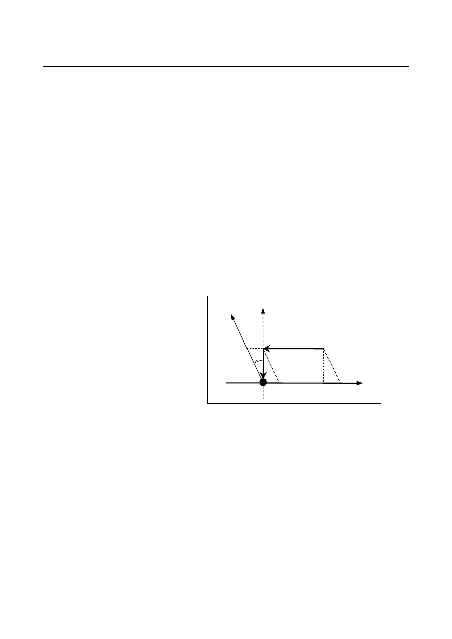
Example) 

Move command for movement from point P0 to point P1 

 >G90G53Y100. 

Move command for movement from point P1 to point P2 

 >G90G53X200. 


<1>  Coordinates of P1 
 

(Absolute coordinates) 

(Machine coordinates) 


 X  -50.000 

 X 

0.000 


 Y  86.603 

 Y  100.000 

<2>  Coordinates of P2 
 

(Absolute coordinates) 

(Machine coordinates) 


 X  150.000 

 X  200.000 


 Y  86.603 

 Y  100.000 


+Y (Angular axis) +Y' (Hypothetical axis)

P1(0,100)

P2(200,100)

+X
(Perpendicular

axis)

P0(0,0)

30

°


21.AXIS CONTROL FUNCTIONS

 PROGRAMMING 

B-63944EN/03


- 726 - 

  - Commands for linear interpolation and linear interpolation type positioning (G01, 

G00) 

The tool moves to a specified position in the Cartesian coordinate 
system when the following is specified: 
(G90)G00X_Y_; (when the Y-axis is an angular axis, the X-axis is a 
perpendicular axis, and the inclination angle is -30

°

or 
(G90)G01X_Y_F_; (when the Y-axis is an angular axis, the X-axis is 
a perpendicular axis, and the inclination angle is -30

°

 
Example)  Examples of positioning 

Move command for movement from point P0 to point P1 

 >G90G00Y100. 

Move command for movement from P1 to P2 

 G90G00X200. 

(1)  When the perpendicular axis/angular axis control disable 

signal (NOZAGC) is set to 0 
<1>  Coordinates of P1 
 

(Absolute coordinates) 

(Machine coordinates) 


 X  

0.000 

 X  57.735 


 Y  100.000 

 Y  115.470 

<2>  Coordinates of P2 
 

(Absolute coordinates) 

(Machine coordinates) 


 X  200.000 

 X  257.735 


 Y  100.000 

 Y  115.470 


30

°

+Y (Angular axis)

P1

P0(0,0)

P2

257.735

200

57.735

115.470

+Y' (Hypothetical axis)

+X (Perpen-

dicular axis)


(2)  When the perpendicular axis/angular axis control disable 

signal (NOZAGC) is set to 1 
<1>  Coordinates of P1 
 

(Absolute coordinates) 

(Machine coordinates) 


 X  

0.000 

 X 

0.000 


 Y  100.000 

 Y  115.470 

<2>  Coordinates of P2 
 

(Absolute coordinates) 

(Machine coordinates) 


 X  200.000 

 X  200.000 


 Y  100.000 

 Y  115.470 


B-63944EN/03

 PROGRAMMING 

21.AXIS CONTROL FUNCTIONS


- 727 - 

30

°

P1

P0(0,0)

P2

200

115.470

+Y (Angular axis)

+Y' (Hypothetical axis) 

+X (Perpendicular 

axis) 


  - Three-dimensional coordinate conversion   

In the three-dimensional coordinate conversion mode, angular 
coordinate system conversion is applied to the workpiece coordinate 
system that has undergone three-dimensional coordinate conversion. 
 

  - Stored stroke limit 

Stored stroke limits under arbitrary angular axis control can be set not 
in a angular coordinate system but in the Cartesian coordinate system 
by setting bits 0, 1, and 2 (AOT, AO2, and AO3) of parameter No. 
8201. 

X

Y

Y'


X

Y

Y'


Fig. 21.5 (c) OT area in a angular coordinate system  Fig. 21.5 (d) OT area in a Cartesian coordinate system 

 
Machine coordinates include a value converted for the angular axis 
and a compensation value for the perpendicular axis, so that a angular 
machine coordinate system as shown in Fig. 21.5 (c) results. 
A stored stroke limit is checked in the machine coordinate system, so 
that the limit area is slanted to form a rhombus as shown in Fig. 21.5 
(c).    In this case, the area cannot be identified intuitively.    So, stroke 
limits are checked not in an actual angular machine coordinate system 
but in a virtual Cartesian machine coordinate system as shown in Fig. 
21.5 (d). 
 
The functions that operate in the Cartesian coordinate system are: 

  Stored stroke check 1 (Both of I and II) 

  Stored stroke check 2 (G22/G23) 

  Stored stroke check 3 

21.AXIS CONTROL FUNCTIONS

 PROGRAMMING 

B-63944EN/03


- 728 - 

  Stored stroke check before move 

The stored stroke check function before move does not work in a 
angular coordinate system.    Unless this function is enabled, and the 
coordinate system is converted to the Cartesian coordinate system, no 
stroke check is made. 

  Stroke limit external setting (function specific to the M series only 

and valid only for OT1) 

  Bit 7 (BFA) of parameter No. 1300 for specifying whether to issue 

an alarm before or after a stroke limit is exceeded (valid for OT1 
and OT3) 

The stored stroke limit functions other than the above work in a 
angular coordinate system. 
 

  - Relationships between this function and axis-by-axis input/output signals 

The table below indicates the relationships between this function and 
the meaning of each controlled axis signal. 
The input/output signals are classified as signals valid for the program 
coordinate system (Cartesian coordinate system) and signals valid for 
the machine coordinate system (angular coordinate system).  In the 
"Classification" column, "Cartesian" is indicated for a signal that is 
valid for the Cartesian coordinate system, and "Angular" is indicated 
for a signal that is valid for the angular coordinate system. 
A signal valid for the Cartesian coordinate system means a signal 
valid for a specified axis, and a signal valid for the angular coordinate 
system is a signal valid for actual machine movement. 
This means that when a movement is made along the perpendicular 
axis by a movement along the angular axis alone: 
 

A signal valid for the Cartesian coordinate system is affected by 
a movement along the angular axis. 


A signal valid for the angular coordinate system is not affected 
by a movement along the angular axis. 

Input signal 

Signal name 

Address

Classification

Remarks 

Interlock for each axis 

*ITx 

G130 

Cartesian 

When a movement is made along the angular axis 
only, interlocking the perpendicular axis does not 
interlock a movement along the perpendicular axis 
made by a movement along the angular axis. 
Caution)  When using the interlock signal for each 

axis, make both of the angular axis and 
perpendicular axis high. 

Overtravel 

*+Lx 
*-Lx 

G114 
G116 

Angular 

This signal is applied to each axis independently.   
(If the perpendicular axis is made high, no alarm is 
issued for the perpendicular axis even when an OT 
alarm is issued for the angular axis.) 

Deceleration signal for 
reference position return 

*DECx 

X009 

Angular 

This signal is applied to each axis independently. 

Servo-off signal 

SVFx 

G126 

Angular 

This signal is applied to each axis independently. 

Control axis detach signal  DTCHx 

G124 

Angular 

This signal is applied to each axis independently. 

Feed axis direction 
selection signal 

+Jx 
-Jx 

G100 
G102 

Cartesian 

A movement is made in the Cartesian coordinate 
system.    (When the +J/-J signal for the angular 
axis is made high, a movement is made also along 
the perpendicular axis.) 

B-63944EN/03

 PROGRAMMING 

21.AXIS CONTROL FUNCTIONS


- 729 - 

Input signal 

Signal name 

Address

Classification

Remarks 

Mirror image 

MIx 

G106 

Angular 

Mirror image is applied to the angular coordinate 
system for each axis independently. 
Caution)  Be sure to turn off the mirror image 

signal for the angular axis and 
perpendicular axis engaged in manual 
operation. 

Manual feed interlock 
signal for each axis 
direction, tool 
compensation value write 
signal 

+MIT1, 
+MIT2 

X004.2, 

Cartesian 

Set the tool compensation parameter in the 
Cartesian coordinate system. 

Machine lock for each 
axis 

MLKx 

G108 

Angular 

This signal is applied to each axis independently. 


Output signal 

Signal name 

Address

Classification

Remarks 

In-position signal 

INPx 

F104 

Angular 

Applied to each axis independently. 

Mirror image check signal  MMIx 

F108 

Angular 

Applied to each axis independently. 

Controlled axis removal 
in-progress signal 

MDTC
Hx 

F110 

Angular 

Applied to each axis independently. 

Travel in-progress signal 

MVx 

F102 

Angular 

Applied to each axis independently. 

Reference position return 
completion signal 

ZPx F094 Cartesian 

Applied to each axis independently. (A manual 
reference position return operation and the first 
automatic reference position return operation after 
power-up need to be performed first for the angular 
axis.) 

2nd reference position 
return completion signal 

ZP2x 

F096 

Cartesian 

Applied to each axis independently. 

3rd reference position 
return completion signal 

ZP3x 

F098 

Cartesian 

Applied to each axis independently. 

4th reference position 
return completion signal 

ZP4x 

F100 

Cartesian 

Applied to each axis independently. 


Limitation 
  - Three-dimensional coordinate conversion 

If the basic three axes in the three-dimensional coordinate conversion 
mode do no include a perpendicular axis and angular axis for arbitrary 
angular axis control, operation cannot be performed normally in a 
correct angular coordinate system. 
 

  - Linear scale with absolute address reference mark 

  For both of the angular axis and perpendicular axis, a linear scale 

with an absolute address reference mark must be used. 

  Reference position return operation must be first completed along 

the angular axis. 

  Return operation cannot be performed along the perpendicular axis 

while return operation is being performed along the angular axis. 


21.AXIS CONTROL FUNCTIONS

 PROGRAMMING 

B-63944EN/03


- 730 - 

 - Synchronous control 

For synchronous control on axes related to arbitrary angular axis 
control, the angular axis and Cartesian axis on the master axis side and 
the angular axis and Cartesian axis on the slave axis side must be 
placed under synchronous control at the same time.  Moreover, 
synchronous control can be exercised between angular axes only or 
between Cartesian axes only. 
If an attempt is made to perform operation under a condition other 
than the above, the alarm PS0375 is issued. 
Example) 

  Path 1                                                                      Path 2 
X1 (Cartesian axis)     

Synchronous

   X2 (Cartesian axis) 

Y1 (angular axis)     

Synchronous

   Y2 (angular axis) 


 - Composite control 

For composite control on axes related to arbitrary angular axis control, 
the angular axis and Cartesian axis on the master axis side and the 
angular axis and Cartesian axis on the slave axis side must be placed 
under composite control at the same time.  Moreover, composite 
control can be exercised between angular axes only or between 
Cartesian axes only. 
If an attempt is made to perform operation under a condition other 
than the above, the alarm PS0375 is issued. 
Example) 

    Path 1                                                        Path 2 
X1 (Cartesian axis)     

composite

   X2 (Cartesian axis) 

Y1 (angular axis)    

composite

   Y2 (angular axis) 


 - Rigid tapping 

As a rigid tapping axis, no angular axis can be used. 


B-63944EN/03

 PROGRAMMING 

21.AXIS CONTROL FUNCTIONS


- 731 - 

  - Functions that cannot be used simultaneously 

  Axis synchronous control, twin table control, parallel axis control, 

polygon turning, rigid tapping, hypothetical axis control, EGB 
function, PMC axis control, superimposed control 


 CAUTION 

1  After arbitrary angular axis control parameter setting, 

be sure to perform manual reference position return 
operation. 

2  Before manual reference position return operation is 

performed along the perpendicular axis, reference 
position return operation along the angular axis must 
be completed (with the reference position return 
completion signal for the angular axis (ZPx) set to 1). 
If reference position return operation is performed 
along the perpendicular axis first, an alarm PS0372 is 
issued.  

3  When the setting is made so that the tool moves 

along the perpendicular axis during manual reference 
position return along the angular axis (bit 2 (AZK) of 
parameter No. 8200 is set to 0), if once manual 
reference position return has been performed along 
the angular axis, also perform manual reference 
position return along the perpendicular axis 
immediately after the operation. 

4  Before attempting to manually move the tool along the 

angular and perpendicular axes simultaneously, set 
perpendicular/angular axis control disable signal 
NOZAGC to 1. 

5  Once the tool has been moved along the angular axis 

when perpendicular/angular axis control disable signal 
NOZAGC has been set to 1, manual reference 
position return must be performed. 

6  The same increment system must be used with the 

angular axis and perpendicular axis. 

7  Before a perpendicular axis reference position return 

check can be made, angular axis reference position 
return operation must be completed. 

8  No rotary axis must be set for the angular axis and 

perpendicular axis. A rotary axis may be specified 
only for a linear axis. 

9  Set a position switch operation range (parameter Nos. 

6930 to 6965) in a angular coordinate system. 


Content      ..     94      95      96      97     ..