FANUC Series 30i/300i/300is-MODEL A. Machining Center System. User's manual - page 88
 

  Index      Manuals     FANUC Series 30i/300i/300is-MODEL A. Machining Center System. User's manual (B-63944EN/03)


Search            copyright infringement  


Content      ..     86      87      88      89     ..


FANUC Series 30i/300i/300is-MODEL A. Machining Center System. User's manual - page 88


 PROGRAMMING 

B-63944EN/03


- 660 - 

20. HIGH-SPEED CUTTING 

FUNCTIONS 

  - Speed control based on the feedrate difference on each axis at a corner 

By using the speed control based on the feedrate difference on each 
axis at a corner, if a feedrate change occurs on an axis on each axis at 
a corner, the feedrate is determined so that any feedrate difference 
exceeding the permissible feedrate difference on that axis that has 
been set for parameter No. 1783 does not occur, and deceleration is 
automatically performed. 
 

(Example)

Program
N1 G01 G91 X100. F5000

N2 Y100.

N1

N2

Tangent feedrate

X-axis feedrate

Y-axis feedrate

The deceleration
based on the feedrate
difference is used.

Tangent feedrate

X-axis feedrate

Y-axis feedrate

The feedrate difference becomes
small, and the feedrate on each

axis becomes smooth.

The tangent feedrate is
smooth, but the feedrate

on each axis is not.

N1

N2

N1

N2

N1

N2

N1

N2


The method of deceleration based on the feedrate difference differs 
depending on the setting made for bit 6 (FNW) of parameter No. 
19500. 
If "0" is set, the largest feedrate that does not exceed the permissible 
feedrate difference set for parameter No. 1783 is assumed to be the 
deceleration feedrate.   

B-63944EN/03

 PROGRAMMING 


- 661 - 

20.HIGH-SPEED CUTTING

FUNCTIONS

In this case, the deceleration feedrate differs if the travel direction 
differs, even if the shape is the same. 
 

Deceleration to

500 mm/min

Deceleration to

354 mm/min

(Example)
If parameter FNW (bit 6 of No. 19500) = 0 and the

permissible feedrate difference = 500 mm/min (on all axes)


If "1" is set, the feedrate is determined not only with the condition that   
the permissible feedrate difference and permissible acceleration on 
each axis are not exceeded, but also that the deceleration feedrate is 
constant regardless of the travel direction if the shape is the same. 
If 1 is set for this parameter, the deceleration feedrate determined with 
the feedrate difference may be up to 30% lower than that determined 
if 0 is set. 
 

Deceleration to

354 mm/min

Deceleration to

354 mm/min

(Example)
If parameter FNW (bit 6 of No. 19500) = 1 and

permissible feedrate difference = 500 mm/min (on all axes)


 PROGRAMMING 

B-63944EN/03


- 662 - 

20. HIGH-SPEED CUTTING 

FUNCTIONS 

  - Speed control with acceleration in circular interpolation 

When high-speed cutting is performed in circular interpolation, helical 
interpolation, or spiral interpolation, the actual tool path has an error 
with respect to the programmed path.    In circular interpolation, this 
error can be approximated from the equation given below. 
 

Specified path

Actual path

r : Maximum radius error (mm)

v

: Feedrate (mm/sec)

r

: Arc radius (mm)

a

: Acceleration (mm/sec

2

)

T

1

: Time constant of

acceleration/deceleration after
interpolation at cutting (sec)

T

2

: Time constant of servo motor (sec)

r  : Error

0

Y

X

r


a

)

2

2

T

2

1

T

(

2

1

r

2

v

)

2

2

T

2

1

T

(

2

1

r

+

=

+

=

................................ (Equation 1) 

 
In actual machining, permissible error 

r is given, so the maximum 

permissible acceleration a (mm/sec

2

) in equation 1 is determined. 

When a specified feedrate causes the radial error from an arc having a 
programmed radius to exceed the permissible error, speed control with 
acceleration in circular interpolation automatically clamps the 
arc-cutting feedrate by using parameter settings. 
 
Let the permissible acceleration calculated from the permissible 
acceleration set for each axis be A.  Then, maximum permissible 
feedrate v with programmed radius r is expressed as follows: 
 

r

A

v

=

........................................................................... (Equation 2) 

 
If a specified feedrate exceeds feedrate v obtained from equation 2, 
the feedrate is clamped at feedrate v automatically. 
The permissible acceleration is specified in parameter No. 1735.    If 
there is a difference in permissible acceleration between two axes for 
circular interpolation, the lower acceleration is regarded as the 
permissible acceleration. 
If the radius of an arc is small, too small value can be calculated as 
deceleration v.    In such a case, the lower feedrate limit can be set in 
parameter No. 1732 to prevent the feedrate from being decreased too 
much. 
 

B-63944EN/03

 PROGRAMMING 


- 663 - 

20.HIGH-SPEED CUTTING

FUNCTIONS

  - Speed control with the acceleration on each axis 

When consecutive small lines are used to form a curve, as in the 
example shown in the figure below, the feedrate differences on each 
axis at the individual corners are not very large. Thus, deceleration 
with the feedrate differences is not effective. Consecutive small 
feedrate differences, however, cause a large acceleration on each axis, 
as a whole. 
In such a case, deceleration can be performed to reduce the impact on 
the machine and the machining error caused by too large an 
acceleration. The deceleration feedrate is determined to be the feedrate 
that does not cause the acceleration on each axis to exceed the 
permissible acceleration set for parameter No. 1737. 
The deceleration feedrate is determined for each corner. The actual 
feedrate is the smaller of the deceleration feedrate determined at the 
start point of the block and that determined at the end point. 
Depending on the specified figure, a very low deceleration feedrate 
may be calculated. In such a case, the lower feedrate limit can be set in 
parameter No. 1738 to prevent the feedrate from being decreased too 
much. 
In the following example, the acceleration (gradient of the broken line 
in the feedrate graph) at too large at corners N2 to N4 and N6 to N8 
and, therefore, deceleration is performed. 

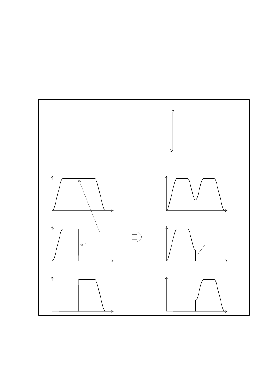
X-axis
feedrate

N1

N2

Y

X

N3

N4

N6

N7

N8

Y-axis
feedrate

Tangent
feedrate

N1

N5

N9

N1

N5

N9

N9

N5


 PROGRAMMING 

B-63944EN/03


- 664 - 

20. HIGH-SPEED CUTTING 

FUNCTIONS 

The method of determining the feedrate with the acceleration differs 
depending on the setting of bit 6 (FNW) of parameter No. 19500. 
If "0" is set, the highest feedrate that does not cause the permissible 
acceleration set for parameter No. 1737 to be exceeded is assumed to 
be the deceleration feedrate.  In this case, the deceleration feedrate 
differs depending on the travel direction even if the shape is the same, 
as shown in the figure below. 
 

(Example) If a circular shape with a radius of 10 mm is specified with small

line blocks

Parameter FNW (bit 6 of No. 19500) = 0

Permissible acceleration = 1000 mm/s

2

 (on all axes)

The feedrate is
higher in these

directions.

Tangent feedrate

Time

F6000


If "1" is set, the feedrate is determined with not only the condition that   
the permissible acceleration on each axis is not exceeded but also the 
condition that the deceleration feedrate is constant regardless of the 
travel direction if the shape is the same. 
If 1 is set for this parameter, the deceleration feedrate determined with 
the feedrate difference or acceleration may be up to 30% lower than 
that determined if 0 is set. 
 

(Example) If a circular shape with a radius of 10 mm is specified with small

line blocks

Parameter FNW (bit 6 of No. 19500) = 1,

radius = 10 mm, permissible acceleration = 1000 mm/s

2

 (on all axes)

The tangent
feedrate is

constant.

Tangent feedrate

Time

F6000


NOTE 


In circular interpolation, the tangent feedrate is 
constant regardless of the setting of the parameter. 


B-63944EN/03

 PROGRAMMING 


- 665 - 

20.HIGH-SPEED CUTTING

FUNCTIONS

  - Smooth speed control 

In speed control with acceleration, the smooth speed control function 
recognizes the entire figure from preceding and following blocks 
including blocks read ahead to make a smooth feedrate determination. 
When a curve is specified with successive minute straight lines, 
programmed values are rounded to the least input increment before 
issued, so the machining profile is approximated with a broken line. 
When the feedrate is determined with acceleration in an ordinary 
manner, an optimum feedrate is automatically calculated exactly for a 
programmed figure, so a large acceleration may result depending on 
the command, which can lead to deceleration. 
In such a case, the use of smooth speed control enables speed control 
by recognizing the entire figure, which provides smooth speed control 
while suppressing local deceleration, therefore increasing the feedrate. 
 

Large acceleration

: Programmed path

: Recognized figure


Also for a part of a programmed figure in which a large acceleration 
would be required, the acceleration is obtained based on the figure 
recognized from multiple blocks, and the feedrate is determined so 
that the acceleration is within the permissible acceleration set in 
parameter No. 1737. 
 

Tangential feedrate

Deceleration with acceleration
in ordinary manner

Smooth speed control

Time

Command with large acceleration


 PROGRAMMING 

B-63944EN/03


- 666 - 

20. HIGH-SPEED CUTTING 

FUNCTIONS 

Smooth speed control obtains the acceleration by using the figure 
recognized from the preceding and following blocks including blocks 
read ahead, so smooth speed control is enabled even in parts in which 
the acceleration increases. 
Smooth speed control is enabled under the following conditions: 
<1> Speed control with acceleration is enabled in the AI contour 

control mode. 

<2>  Successive linear interpolation commands are specified. 
<3>  Bit 0 (HPF) of parameter No. 19503 is set to 1. 
 

 CAUTION 


When smooth speed control is used, the feedrate in 
a certain figure such as a corner may become 
larger than the feedrate obtained by ordinary speed 
control with acceleration.    For corners, set 
parameter No. 1783, which is the permissible 
feedrate difference parameter for speed control with 
the feedrate difference at corners, to perform 
appropriate deceleration by speed control with the 
corner feedrate difference. 


  - Speed control with the cutting load 

Usually, the cutting resistance produced when machining is performed 
with the bottom of the cutter as the tool lowers along the Z-axis is 
greater than the cutting resistance produced when machining is 
performed with the side of the cutter as the tool rises along the Z-axis.   
Therefore, deceleration is required. 
In AI contour control, the tool travel direction on the Z-axis is used as 
a condition for calculating the machining feedrate. 
This function is enabled when bit 4 (ZAG) of parameter No. 8451 is 
set to 1. 


During ascent on the Z-axis 

θ


During descent on the Z-axis 

B-63944EN/03

 PROGRAMMING 


- 667 - 

20.HIGH-SPEED CUTTING

FUNCTIONS

 
The descent angle 

θ

 during descent on the Z-axis (angle formed by the 

XY plane and the tool center path) is as shown in the figure.  The 
descent angle is divided into four areas, and the override values for the 
individual areas are set for the following parameters: 
 

Parameter No. 8456 for area 2 
Parameter No. 8457 for area 3 
Parameter No. 8458 for area 4 

 
For area 1, however, no parameter is available, and an override of 
100% is used at all times.    The feedrate obtained according to other 
feedrate control is multiplied by the override value of the area to 
which descent angle 

θ

 belongs. 


Area1 0º 


θ

 < 30º 

Area2 30º 


θ

 < 45º 

Area3 45º 


θ

 < 60º 

Area4 60º 


θ

 < 90º 

 
The feedrate can be overridden with an inclination by setting bit 1 
(ZG2) of parameter No. 19515 to 1.    In this case, specify the override 
value for area 1 in parameter No. 19516. 
 

XY plane

Z

30

°

45

°

60

°

90

°

Area1

Area2

Area3

Area4


Content      ..     86      87      88      89     ..