FANUC Series 30i/300i/300is-MODEL A. Machining Center System. User's manual - page 57
 

  Index      Manuals     FANUC Series 30i/300i/300is-MODEL A. Machining Center System. User's manual (B-63944EN/03)


Search            copyright infringement  


Content      ..     55      56      57      58     ..


FANUC Series 30i/300i/300is-MODEL A. Machining Center System. User's manual - page 57


15.COMPENSATION FUNCTION

 PROGRAMMING 

B-63944EN/03


- 412 - 

(b)  When the absolute position after movement in real time is 

singular, the rotation axis closer to the workpiece moves as 
commanded. 


Example: 
 

The rotation axis about the Z-axis is the master axis, 
the rotation axis about the Y-axis is the slave axis, and 
the reference tool axis direction is along the Z-axis on 
a 5-axis machine of tool rotation type. 


Assume that the workpiece setting error around the 
Z-axis exists, and the tool posture after the 
compensation of tool direction becomes like following 
figure. 


In this case, the rotation axis about Z-axis (the rotaion 
axis closer to the workpiece) moves as commanded. 


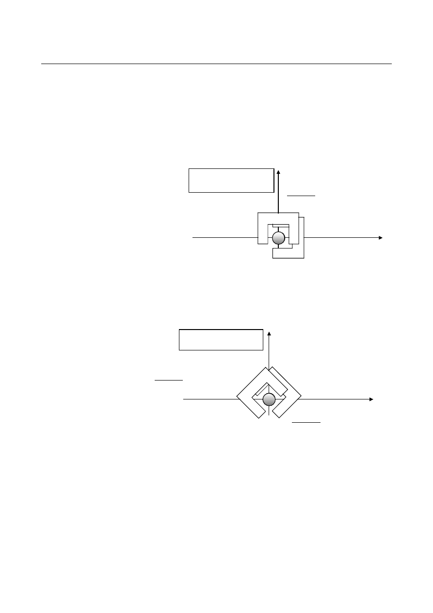
The tool posture in the 
absolute coordinate system

The tool posture after movement
(Singular) 

The tool posture before movement 

The tool posture in the 
machine coordinate system

The tool posture after movement 
(Singular) 
 

The tool posture before movement 
(Singular) 
 

B-63944EN/03

 PROGRAMMING 

15.COMPENSATION FUNCTION


- 413 - 

(2)  In the case that the current machine position is not singular and 

the position after movement in real time is singular. 
: The rotation axis closer to workpiece does not move. 


Example: 
 

The rotation axis about the Z-axis is the master axis, the 
rotation axis about the Y-axis is the slave axis, and the 
reference tool axis direction is along the Z-axis on a 5-axis 
machine of tool rotation type. 


Assume that the tool posture after the compensation of tool 
direction becomes like following figure. 


In this case, the rotation axis about the Z-axis (the rotation 
axis closer to the workpiece) does not move. (Only the 
rotation axis closer to the tool moves.) 


The tool posture in the 
machine coordinate system
 

The calculated tool posture   
after movement 
(Singular) 
 

The tool posture before movement 
(Not singular) 

The actual tool posture   
after movement 
 

15.COMPENSATION FUNCTION

 PROGRAMMING 

B-63944EN/03


- 414 - 

(3)  In the case that the current machine position is singular and the 

position after movement in real time is not singular. 
: In order to position the tool to the correct direction, there are 
two pairs of solutions of rotation axes angles within 0 – 360deg. 
A solution with which the rotation axis closer to workpiece 
moves shorter is selected.   


Example: 
 

The rotation axis about the Z-axis is the master axis, the 
rotation axis about the Y-axis is the slave axis, and the 
reference tool axis direction is along the Z-axis on a 5-axis 
machine of tool rotation type. 


Assume that the tool posture after the compensation of tool 
direction becomes like following figure. 


In this case, the rotation axes move to the positions with 
which the rotation axis about the Z-axis (the rotation axis 
closer to workpiece) moves shorter. (The tool moves in the 
direction of the arrow in the above figure.) 


The tool does not move in the direction of the arrow in the 
following figure. 


The tool posture in the 
machine coordinate system

The tool posture before movement 
(Singular) 

The tool posture after movement 
(Not singular) 
 

The tool posture   
before movement 
 

The tool posture   
after movement 
 

B-63944EN/03

 PROGRAMMING 

15.COMPENSATION FUNCTION


- 415 - 

(4)  In the case that the current machine position is not singular and 

the position after movement in real time is not singular. 
: In order to position the tool to the correct direction, there are 
two pairs of solutions of rotation axes angles within 0 – 360deg. 
One solution with which the rotation axes don’t pass the singular 
point is selected. And, the rotation axes move to the positions of 
the selected solution. 


Example: 
 

The rotation axis about the Z-axis is the master axis, the 
rotation axis about the Y-axis is the slave axis, and the 
reference tool axis direction is along the Z-axis on a 5-axis 
machine of tool rotation type. 


Assume that the tool posture after the compensation of tool 
direction becomes like following figure. 


In this case, the rotation axes move to the positions with 
which the rotation axes don’t pass the singular point. (The 
tool moves in the direction of the arrow in the above 
figure.) 


The tool does not move in the direction of the arrow in the 
following figure. 


The tool posture after movement 
 

The tool posture   
before movement 
 

The tool posture in the 
machine coordinate system

The tool posture after movement 
(Not singular) 
 

The tool posture before movement 
(Not singular) 
 

15.COMPENSATION FUNCTION

 PROGRAMMING 

B-63944EN/03


- 416 - 

  - When the tool posture is closer to a singular point posture on a 5-axis machine 

If tool direction compensation is performed on a 5-axis machine, and 
the tool posture gets closer to a singular point posture during 
execution of a block, the rotation axis closer to the workpiece may 
make a large motion. 
 
In addition, if parameter No. 11204 (angle for deciding on a singular 
point posture) is set with a value, it is likely that the tool direction and 
tool tip position may be incorrect while the tool is decided to be in a 
singular point posture.    Furthermore, it is likely that the rotation axis 
closer to the tool may abruptly move by the parameter-set angle.    So, 
do not set parameter No. 11204 with a value larger than necessary. 
 

  - Notes in the case that rotary axes have movable range 

When the tool direction is compensated on a 5-axis machine, there can 
be the case that the machine position does not pass the singular 
posture during a progress of work at all. 
In this case, in accordance with 4) described above, the solution with 
which the rotary axes don’t pass the singular point is always selected.   
Therefore, in this case, the movement direction(area) depends on 
where the tool exists in comparison with the singular point, because 
the tool position is always selected so that the rotary axes don’t pass 
the singular point.   
In the case that rotary axes have movable range and a singular point 
exists in that range, Workpiece setting error compensation must be 
activated after the rotary axes have been moved to the range where the 
rotary axes should move, that is, the range (A) between the lower limit 
and the singular point or the range(B) between the upper limit and the 
singular point. 
Generally speaking, if (A) and (B) are different, it is recommended 
that the larger one is selected. 


Movable range of 
rotary axis 

Lower limit of 
movable range

Upper limit of 
movable range 

Singular position 

0deg

(A) (B) 

Workpiece setting error compensation must be activated after the rotary 
axes have been moved to the range where the rotary axes should move 

B-63944EN/03

 PROGRAMMING 

15.COMPENSATION FUNCTION


- 417 - 

The following is an example that the movement direction(area) 
depends on position of the rotary axes before starting workpiece 
setting error compensation. 
The Master axis is C axis around Z axis, and the Slave axis is B axis 
around Y axis(when C=0). Tool direction is +Z when B=C=0. 
Here, suppose B axis’ movable range is –45 deg to +100 deg. 


When B=0, the tool posture does not change even if C axis moves.  
That means the position B=0 is singular point. 


Firstly, suppose the following program without Workpiece setting 
error. 
 
Program without Workpiece setting error 
O1 
N10 G5.1 Q1 
N20 G90 G01 B-1.0 C0 F1000 
N30 G43.4 H1 
N40 X0 Y0 Z0 
N50 B90.0 C90.0 


C axis rotates around Z axis. 

B axis rotates around Y axis. 

Figure when B = C = 0 

B axis movable range

- 45deg 

100deg

Singular position


0deg

 N40 end 

 B 

Absolute -1.0

0.0

Machine -1.0

0.0


15.COMPENSATION FUNCTION

 PROGRAMMING 

B-63944EN/03


- 418 - 


At N50, machine position moves to B90.0 and C90.0, as commanded. 
 
Next, suppose there is the error -2.0deg around Y axis and Workpiece 
setting error 

b=-2.000 is set, and the block N25 is added as follows : 

 
On O2, B axis position is –1.0 before Workpiece setting error 
compensation is activated, which is between the lower limit of 
movable range and the singular point of B axis. 


  In the middle of N50 

 N50 end 

 B 

Absolute 90.0

90.0

Machine 90.0

90.0


B axis movable 
range 

-45deg 

100deg

B axis position of N20 before Workpiece 
setting error compensation is activated 

Singular point 0deg

B-63944EN/03

 PROGRAMMING 

15.COMPENSATION FUNCTION


- 419 - 

O2 
N10 G5.1 Q1 
N20 G90 G01 B-1.0 C0 F1000 ; B axis machine position is between 

the lower limit and the singular 
point 

N25 G54.4 P1                                         
N30 G43.4 H1 
N40 X0 Y0 Z0 
N50 B90.0 C90.0 


During N50, Machine position does not pass the singular point at all. 
So, B axis moves from the starting position(–1.0) to the 
position(B–90.0,C–90.0). As the result, B axis moves over the lower 
limit of B axis movable range. 
 
Therefore, suppose the program O3 in which B axis position is 
changed to 1.0, which is between the singular point and the upper 
limit, before Workpiece setting error compensation is activated. 
Then, the range between the singular point and the upper limit of B 
axis movable range is the range where B axis should move. 


 N40 end 

 B 

Absolute 1.0

0.0

Machine -1.0

0.0


  In the middle of N50 

B axis movable 
range 

-45deg 

100deg

Singular point 0deg

B axis position of N20 before Workpiece 
setting error compensation is activated 


Content      ..     55      56      57      58     ..