FANUC Series 30i/300i/300is-MODEL A. Machining Center System. User's manual - page 50
 

  Index      Manuals     FANUC Series 30i/300i/300is-MODEL A. Machining Center System. User's manual (B-63944EN/03)


Search            copyright infringement  


Content      ..     48      49      50      51     ..


FANUC Series 30i/300i/300is-MODEL A. Machining Center System. User's manual - page 50


 PROGRAMMING 

B-63944EN/03


- 356 - 

14. FUNCTIONS TO SIMPLIFY 

PROGRAMMING 

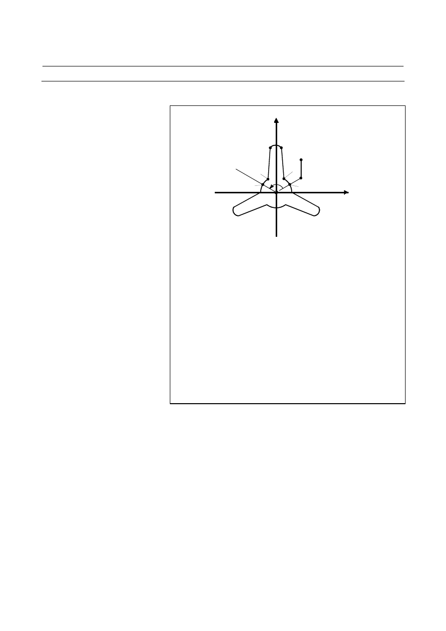
Example 
 - Rotational copying 


Start point 

Main program 

O1000 ; 

N10 G92 X40.0 Y50.0 ; 
N20 G00 G90 X_ Y_ ;                                  (P0)
N30 G01 G17 G41 X_ Y_ D01 F10 ;        (P1) 
N40 G72.1 P2000 L3 X0 Y0 R120.0 ;       
N50 G40 G01 X_ Y_ I_ J_ ;                        (P0) 
N60 G00 X40.0 Y50.0 ; 
N70 M30 ; 

Sub program 

O2000 G03 X_ Y_ R30.0 ;             (P2) 
N100 G01 X_ Y_ ;                    (P3)

N200 G03 X_ Y_ R10.0 ;              (P4) 
N300 G01 X_ Y_ ;                    (P5) 
N400 G03 X_ Y_ R30.0 ;              (P6) 
N500 M99; 

120

°

Y

P3

P0

P1

P6

P5

P4

P2


B-63944EN/03

 PROGRAMMING 


- 357 - 

14.FUNCTIONS TO SIMPLIFY

PROGRAMMING

  - Rotational copying (spot boring) 

Main program

O3000 ;
N10 G92 G17 X80.0 Y50.0 ;              (P0)
N20 G72.1 P4000 L6 X0 Y0 R60.0 ;
N30 G80 G00 X80.0 Y50.0 ;              (P0)
N40 M30 ;

Subprogram

O4000 N100 G90 G81 X_ Y_ R_ Z_ F_ ;      (P1)
N200 M99 ;

Y

P1

P0

Start point

60°

X


 - Linear copying 

Main program

O1000 ;
N10 G92 X-20.0 Y0 ;
N20 G00 G90 X0 Y0 ;
N30 G01 G17 G41 X20. Y0 D01 F10 ;

(P0)

N40 Y20. ;

(P1)

N50 X30. ;

(P2)

N60 G72.2 P2000 L3 I70.0 J0 ;
N70 X_ Y_ ;

(P8)

N80 X0 ;
N90 G00 G40 X-20.0 Y0 ;
N100 M30 ;

Subprogram

O2000 G90 G01 X_ ;

(P3)

N100 Y_ ;

(P4)

N200 G02 X_ I_ ;

(P5)

N300 G01 Y_ ;

(P6)

N400 X_ ;

(P7)

N500 M99 ;

Start
point

P8

P0

P1

P2

P4

P3

70

70

70

X

P5

P7

Y

P6


 PROGRAMMING 

B-63944EN/03


- 358 - 

14. FUNCTIONS TO SIMPLIFY 

PROGRAMMING 

  - Combination of rotational copying and linear copying (bolt hole circle) 

Main program

O1000 ;
N10 G92 G17 X100.0 Y80.0 ;             (P0)
N20 G72.1 P2000 X0 Y0 L8 R45.0 ;
N30 G80 G00 X100.0 Y80.0 ;             (P0)
N40 M30 ;

Subprogram (rotational copy)

O2000 N100 G72.2 P3000 I0 J_ L3 ;
N200 M99 ;

Y

X

45°

P1

P0 Start point

Subprogram (linear copy)

O3000 N110 G90 G81 X_ Y_ R_ Z_ F_ ;      (P1)
N210 M99 ;


B-63944EN/03

 PROGRAMMING 


- 359 - 

14.FUNCTIONS TO SIMPLIFY

PROGRAMMING

14.2 

THREE-DIMENSIONAL COORDINATE SYSTEM 
CONVERSION 

 
Coordinate system conversion about an axis can be carried out if the 
center of rotation, direction of the axis of rotation, and angular 
displacement are specified. This function is very useful in 
three-dimensional machining by a die-sinking machine or similar 
machine.  For example, if a program specifying machining on the 
XY plane is converted by the three-dimensional coordinate system 
conversion function, the identical machining can be executed on a 
desired plane in three-dimensional space. 


For milling machining 


X

Y

Z

Z

Y

X

Three-dimensional coordinate system conversion


For lathe cutting 

X

X'

Z'

Z

Surface to be
machined

B

#3

#2

#1

#4

Y

Z

Machining such as milling, pocketing, and drilling is performed.


 PROGRAMMING 

B-63944EN/03


- 360 - 

14. FUNCTIONS TO SIMPLIFY 

PROGRAMMING 

Format 

M


G68 Xp

X1

 Yp

y1

 Zp

z1

 I

i1

 J

j1

 K

k1

 R

α

 ; 

Starting three-dimensional coordinate system 


    : 

conversion


    : 

Three-dimensional coordinate system conversion 

 mode


G69 ;   

Canceling three-dimensional coordinate system 

conversion


Xp, Yp, Zp  : Center of rotation (absolute coordinates) on the X, Y, and Z axis or parallel 

axes 

I, J, K   

: Direction of the axis of rotation 

R  

: Angular displacement 


T


G68.1 Xp

X1

 Yp

y1

 Zp

z1

 I

i1

 J

j1

 K

k1

 R

α

 ; 

Starting three-dimensional coordinate system 


    : 

conversion


    : 

Three-dimensional coordinate system conversion 

 mode


G69.1 ;   

Canceling three-dimensional coordinate system 

 conversion


Xp, Yp, Zp  : Center of rotation (absolute coordinates) on the X, Y, and Z axis or parallel 

axes 

I, J, K   

: Direction of the axis of rotation 

R  

: Angular displacement 


NOTE 


The G code of this function is hereinafter described 
using the format (G68/G69) for the machining center 
system in this section. 


Explanation 
  - Command for three-dimensional coordinate system conversion (program 

coordinate system) 

N1  G68 Xp x

1

 Yp y

1

 Zp z

1

 I i

1

 J j

1

 K k

1

 R 

α

 ; 

N2  G68 Xp x

2

 Yp y

2

 Zp z

2

 I i

2

 J j

2

 K k

2

 R 

β

 ; 

N3 
 : 
Nn G69 ; 

Three-dimensional coordinate system conversion can be executed 
twice. 
In the N1 block, specify the center, direction of the axis of rotation, 
and angular displacement of the first rotation. 
 

B-63944EN/03

 PROGRAMMING 


- 361 - 

14.FUNCTIONS TO SIMPLIFY

PROGRAMMING

When this block is executed, the center of the original coordinate 
system is shifted to (x

1

, y

1

, z

1

), then rotated around the vector (i

1

, j

1

k

1

) by angular displacement 

α

. The new coordinate system is called 

X'Y'Z'. In the N2 block, specify the center, direction of the axis of 
rotation, and angular displacement of the second rotation. In the N2 
block, specify coordinates and the angle with the coordinate system 
formed after the N1 block in Xp, Yp, Zp, I, J, K, and R. When the N2 
block is executed, the X'Y'Z' coordinate system is shifted to (x

2

, y

2

, z

2

), 

then rotated around the vector (i

2

, j

2

, k

2

) by angular displacement 

β

The newest coordinate system is called X''Y''Z''. In the subsequent N3 
block, coordinates in the X''Y''Z'' coordinate system are specified with 
Xp, Yp, and Zp. The X''Y''Z'' coordinate system is called the program 
coordinate system. 
If (Xp, Yp, Zp) is not specified in the N2 block, (Xp, Yp, Zp) in the 
N1 block is assumed to be the center of the second rotation (the N1 
and N2 blocks have a common center of rotation). If the coordinate 
system is to be rotated only once, the N2 block need not be specified. 


Example)   G68 Xx

0

 Yy

0

 Zz

0

 I0 J0 K1 R

α

 ; 

                        G68                        I1 J0 K0 R

β

 ; 

Z

Y

X

O (x

0

, y

0

, z

0

Z"

Z'

Y"

Y'

α

P (x, y, z) 

β


β


X, Y, Z 

:  Workpiece coordinate system 

X', Y', Z' 

:  Coordinate system formed after the first conversion 

X", Y", Z" 

:  Coordinate system formed after the second conversion 

α


:  Angular displacement of the first rotation 

β


:  Angular displacement of the second rotation 

O (x

0

, y

0

, z

0

:  Center of rotation 

P (x, y, z) 

:  Coordinates in the X''Y''Z'' coordinate system (program 

coordinate system) 

α


 PROGRAMMING 

B-63944EN/03


- 362 - 

14. FUNCTIONS TO SIMPLIFY 

PROGRAMMING 

 - Format error 

If one of the following format errors is detected, alarm PS5044 occurs: 
1.  When I, J, or K is not specified in a block with G68   
 

(a parameter of coordinate system rotation is not specified) 

2.  When I, J, and K are all set to 0 in a block with G68 
3.  When R is not specified in a block with G68 
 

  - Center of rotation 

Specify absolute coordinates with Xp, Yp, and Zp in the G68 block. 
 

  - Equation for three-dimensional coordinate system conversion 

The following equation shows the general relationship between (x, y, 
z) in the program coordinate system and (X, Y, Z) in the original 
coordinate system (workpiece coordinate system). 

( )

+

=

1

1

1

1

z

y

x

z

y

x

M

Z

Y

X


When conversion is carried out twice, the relationship is expressed as 
follows: 

( )( )

( )

+

+

=

1

1

1

2

2

2

1

2

1

z

y

x

z

y

x

M

z

y

x

M

M

Z

Y

X


X, Y, Z 

:  Coordinates in the original coordinate system 


  (workpiece coordinate system) 

x, y, z 

:  Programmed value 


  (coordinates in the program coordinate system) 

x

1

, y

1

, z

1

  :  Center of rotation of the first conversion 

x

2

, y

2

, z

2

  :  Center of rotation of the second conversion   


  (coordinates in the coordinate system formed after the   


first 

conversion) 

M

1


:  First conversion matrix 

M

2


:  Second conversion matrix 

 
M

1

 and M

2

 are conversion matrices determined by an angular 

displacement and rotation axis. Generally, the matrices are expressed 
as shown below. 

+

+

+

+

+

+

θ

θ

θ

θ

θ

θ

θ

θ

θ

θ

θ

θ

θ

θ

θ

cos

)

1

(

sin

)

cos

1

(

sin

)

cos

1

(

sin

)

cos

1

(

cos

)

1

(

sin

)

cos

1

(

sin

)

cos

1

(

sin

)

cos

1

(

cos

)

1

(

2

3

2

3

1

3

2

2

3

1

1

3

2

2

2

2

2

3

2

1

2

3

1

3

2

1

2

1

2

1

n

n

n

n

n

n

n

n

n

n

n

n

n

n

n

n

n

n

n

n

n

n

n

n


n

1

  :  Cosine of the angle made by the rotation axis and X-axis i/p 

n

2

  :  Cosine of the angle made by the rotation axis and Y-axis j/p 

n

3

  :  Cosine of the angle made by the rotation axis and Z-axis k/p 

θ

 : Angular displacement 

Value p is obtained by the following: 

2

2

2

k

j

i

p

+

+

=


B-63944EN/03

 PROGRAMMING 


- 363 - 

14.FUNCTIONS TO SIMPLIFY

PROGRAMMING

Conversion matrices for rotation on two-dimensional planes are 
shown below: 
(1)  Coordinate system conversion on the XY plane 

=

1

0

0

0

cos

sin

0

sin

cos

θ

θ

θ

θ

M


(2)  Coordinate system conversion on the YZ plane 

=

θ

θ

θ

θ

cos

sin

0

sin

cos

0

0

0

1

M


(3)  Coordinate system conversion on the ZX plane 

=

θ

θ

θ

θ

cos

0

sin

0

1

0

sin

0

cos

M


  - Three basic axes and their parallel axes 

Three-dimensional coordinate system conversion can be applied to a 
desired combination of three axes selected out of the basic three axes 
(X, Y, Z) and their parallel axes. The three-dimensional coordinate 
system subjected to three-dimensional coordinate system conversion is 
determined by axis addresses specified in the G68 block. If Xp, Yp, or 
Zp is not specified, X, Y, or Z of the basic three axes is assumed. 
However, if the basic three axes are not specified in parameter 1022, 
alarm PS0048 occurs. 
In a single G68 block, both a basic axis and a parallel axis cannot be 
specified.  
If this is attempted, alarm PS0047 occurs. 
(Example) 
 

When U-axis, V-axis, and W-axis are parallel to the X-axis, 
Y-axis, and Z-axis respectively 


G68    X_ I_ J_ K_ R_ ; 

XYZ coordinate system 


G68    U_V_ Z_ I_ J_ K_ R_ ;  UVZ coordinate system 


G68    W_ I_ J_ K_ R_ ; 

XYW coordinate system 


  - Specifying the second conversion 

Three-dimensional coordinate system conversion can be executed 
twice.  The center of rotation of the second conversion must be 
specified with the axis addresses specified for the first conversion. If 
the axis addresses of the second conversion are different from the axis 
addresses of the first conversion, the different axis addresses are 
ignored. An attempt to execute three-dimensional coordinate system 
conversion three or more times causes alarm PS5043. 


Content      ..     48      49      50      51     ..