FANUC Series 30i/300i/300is-MODEL A. Machining Center System. User's manual - page 30
 

  Index      Manuals     FANUC Series 30i/300i/300is-MODEL A. Machining Center System. User's manual (B-63944EN/03)


Search            copyright infringement  


Content      ..     28      29      30      31     ..


FANUC Series 30i/300i/300is-MODEL A. Machining Center System. User's manual - page 30


7.COORDINATE SYSTEM

 PROGRAMMING 

B-63944EN/03


- 196 - 

Example 


M


X

X’

Y’

Y

Tool position

A

160

100

100

100

200

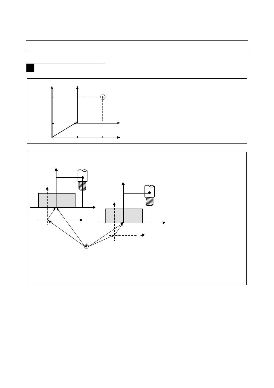
If G92X100Y100; is commanded when the tool is positioned
at (200, 160) in G54 mode, workpiece coordinate system 1
(X' - Y') shifted by vector A is created.

New workpiece coordinate system

Original workpiece coordinate system

G54 workpiece coordinate system

60


Suppose that a G54 workpiece coordinate 
system is specified.    Then, a G55 workpiece 
coordinate system where the black circle on 
the tool (figure at the left) is at (600.0,1200.0) 
can be set with the following command if the 
relative relationship between the G54 
workpiece coordinate system and G55 
workpiece coordinate system is set correctly:

G92X600.0Z1200.0; 

Also, suppose that pallets are loaded at two 
different positions.    If the relative relationship 
of the coordinate systems of the pallets at the 
two positions is correctly set by handling the 
coordinate systems as the G54 workpiece 
coordinate system and G55 workpiece 
coordinate system, a coordinate system shift 
with G92 in one pallet causes the same 
coordinate system shift in the other pallet.   
This means that workpieces on two pallets 
can be machined with the same program just 
by specifying G54 or G55. 

G54 workpiece coordinate system 

1200.0 

X'

600.0 

600.0

1200.0

G55 workpiece coordinate system

Z' 

Z'

X

X' - Z'  ...........New workpiece coordinate system 
X - Z  .............Original workpiece coordinate system 
A : Offset value created by G92 
B : Workpiece origin offset value in the G54 
C : Workpiece origin offset value in the G55 

A

X' 

A


B-63944EN/03

 PROGRAMMING 

7.COORDINATE SYSTEM


- 197 - 

Example 


T


X

X'

Tool position

A

160

100

100

100

200

If G50X100Z100; is commanded when the tool is
positioned at (200, 160) in G54 mode, workpiece
coordinate system 1 (X' - Z') shifted by vector A is
created.

New workpiece coordinate system

Original workpiece coordinate system

G54 workpiece coordinate system

 60

Z

Z'


G54 workpiece coordinate system

Z

Z

X'

600.0

Z'

Z'

X

X

Suppose that a G54 workpiece coordinate
system is specified.    Then, a G55
workpiece coordinate system where the
black tool nose point on the tool (figure at
the left) is at (600.0,1200.0) can be set
with the following command if the relative
relationship between the G54 workpiece
coordinate system and G55 workpiece
coordinate system is set correctly:

G50X600.0Z1200.0;

Also, suppose that loading is performed at
two different places and that the G54 and
G55 workpiece coordinate systems are
set for these two places. If the relative
relationship between the coordinate
systems in the two places is correctly set,
a coordinate system shift with G50 in one
loading place causes the same
coordinate system shift in the other
loading place. This means that
workpieces on the two loading positions
can be machined with the same program
just by specifying G54 or G55.

X' - Z'............ New workpiece coordinate system
X - Z ............. Original workpiece coordinate system
A : Offset value created by G50
B : Workpiece origin offset value in G54
C : Workpiece origin offset value in G55

A

B

C

A

X'

1200.0

1200.0

600.0

G55 workpiece coordinate system


7.COORDINATE SYSTEM

 PROGRAMMING 

B-63944EN/03


- 198 - 

7.2.4 

Workpiece Coordinate System Preset (G92.1) 

 
The workpiece coordinate system preset function presets a workpiece 
coordinate system shifted by manual intervention to the pre-shift 
workpiece coordinate system.  The latter system is displaced from 
the machine zero point by a workpiece origin offset value. 
There are two methods for using the workpiece coordinate system 
preset function.  One method uses a programmed command.  The 
other uses MDI operations on the absolute position display screen, 
relative position display screen, and overall position display screen 
(see III-12.1.4). 


Format 

M


G92.1 

IP

 0 ; 

IP

 0 : Specifies axis addresses subject to the workpiece 

coordinate system preset operation.    Axes that are 
not specified are not subject to the preset operation. 


T


G50.3 

IP

0 ;   

(G92.1 

IP

 0; for G code system B or C)


IP

 0 : Specifies axis addresses subject to the workpiece 

coordinate system preset operation.    Axes that are 
not specified are not subject to the preset operation. 


Explanation 

When manual reference position return operation is performed in the 
reset state, a workpiece coordinate system is shifted by the workpiece 
origin offset value from the machine coordinate system zero point.  
Suppose that the manual reference position return operation is 
performed when a workpiece coordinate system is selected with G54.   
In this case, a workpiece coordinate system is automatically set which 
has its origin displaced from the machine zero point by the G54 
workpiece origin offset value; the distance from the origin of the 
workpiece coordinate system to the reference position represents the 
current position in the workpiece coordinate system. 


Reference position

G54 workpiece coordinate system

Workpiece origin

Manual reference position return

Machine zero point

G54 workpiece
origin offset value


B-63944EN/03

 PROGRAMMING 

7.COORDINATE SYSTEM


- 199 - 

If an absolute position detector is provided, the workpiece coordinate 
system automatically set at power-up has its origin displaced from the 
machine zero point by the G54 workpiece origin offset value.    The 
machine position at the time of power-up is read from the absolute 
position detector and the current position in the workpiece coordinate 
system is set by subtracting the G54 workpiece origin offset value 
from this machine position.    The workpiece coordinate system set by 
these operations is shifted from the machine coordinate system using 
the commands and operations listed below. 
 
(a)  Manual intervention performed when the manual absolute signal 

is off 

(b)  Move command executed in the machine lock state 
(c)  Movement by handle interruption 
(d)  Operation using the mirror image function   
(e)  Shifting the workpiece coordinate system by setting the local 

coordinate system or workpiece coordinate system 

 
In the case of (a) above, the workpiece coordinate system is shifted by 
the amount of movement during manual intervention. 
 

WZn

-

Machine zero point

Workpiece origin
offset value

WZo

G54 workpiece
coordinate system before
manual intervention

G54 workpiece coordinate

system after manual

intervention

Po

Pn

Amount of
movement during
manual intervention


In the operation above, a workpiece coordinate system once shifted 
can be preset using G code (G92.1) specification or MDI operation to 
a workpiece coordinate system displaced by a workpiece origin offset 
value from the machine zero point.   
Bit 3 (PPD) of parameter No. 3104 specifies whether to preset relative 
coordinates (RELATIVE) as well as absolute coordinates. 
When no workpiece coordinate system option (G54 to G59) is 
selected, the workpiece coordinate system is preset to the coordinate 
system with its origin placed at the reference position. 
 

7.COORDINATE SYSTEM

 PROGRAMMING 

B-63944EN/03


- 200 - 

Limitation 
 - Tool radius 

 tool nose radius compensation, tool length compensation, tool 

offset 

When using the workpiece coordinate system preset function, cancel 
compensation modes: Tool radius 

 tool nose radius compensation, 

tool length compensation, and tool offset.    If the function is executed 
without canceling these modes, compensation vectors are cancelled. 
 

M


  - Tool length compensation 

When using the workpiece coordinate system preset function, cancel 
tool length compensation. If the function is executed without 
canceling these modes, compensation vectors are cancelled. 


 - Program restart 

The workpiece coordinate system preset function is not executed 
during program restart. 
 

 - Prohibited modes 

Do not use the workpiece coordinate system preset function when the 
scaling, coordinate system rotation, programmable image, or figure 
copy mode is set. 


B-63944EN/03

 PROGRAMMING 

7.COORDINATE SYSTEM


- 201 - 

7.2.5 

Addition of Workpiece Coordinate System Pair (G54.1 or G54) 

 
Besides the six workpiece coordinate systems (standard workpiece 
coordinate systems) selectable with G54 to G59, 48 or 300 additional 
workpiece coordinate systems (additional workpiece coordinate 
systems) can be used. 
 

Format 
  - Selecting the additional workpiece coordinate systems 

G54.1Pn ; 

or

 G54Pn ; 

Pn  : Codes specifying the additional workpiece coordinate 

systems 

n    :   1 to 48 or 1 to 300 


  - Setting the workpiece origin offset value in the additional workpiece coordinate 

systems (G10) 

G10L20Pn 

IP

_; 

Pn  : Codes specifying the workpiece coordinate system for 

setting the workpiece origin offset value 

n    : 1 to 48 or 1 to 300 
IP_  :   Axis addresses and a value set as the workpiece 

origin offset 


Explanation 
  - Selecting the additional workpiece coordinate systems


When a P code is specified together with G54.1 (G54), the 
corresponding coordinate system is selected from the additional 
workpiece coordinate systems (1 to 48 or 1 to 300). 
A workpiece coordinate system, once selected, is valid until another 
workpiece coordinate system is selected.  Standard workpiece 
coordinate system 1 (selectable with G54) is selected at power-on. 
G54.1 P1 ......... Additional workpiece coordinate system 1 
G54.1 P2 ......... Additional workpiece coordinate system 2 
        : 
G54.1 P48 ....... Additional workpiece coordinate system 48 
        : 
G54.1 P300 ..... Additional workpiece coordinate system 300 
 

7.COORDINATE SYSTEM

 PROGRAMMING 

B-63944EN/03


- 202 - 

As with the standard workpiece coordinate systems, the following 
operations can be performed for a workpiece origin offset in an 
additional workpiece coordinate system: 
 
(1)  The workpiece origin offset value setting screen can be used to 

display and set a workpiece origin offset value. 

(2)  The G10 function enables a workpiece origin offset value to be 

set by programming (refer to II-7.2.3). 

(3)  A custom macro allows a workpiece origin offset value to be 

handled as a system variable. 

(4)  Workpiece origin offset data can be entered or output as external 

data. 

(5)  The PMC window function enables workpiece origin offset data 

to be read as program command modal data. 


  - Setting the workpiece origin offset value in the additional coordinate systems 

(G10) 

When a workpiece origin offset value is specified using an absolute 
value, the specified value is the new offset value.  When it is 
specified using an incremental value, the specified value is added to 
the current offset value to obtain a new offset value. 
 

Limitation 
  - Specifying P codes 

A P code must be specified after G54.1 (G54).  If G54.1 is not 
followed by a P code in the same block, additional workpiece 
coordinate system 1 (G54.1P1) is assumed. 
If a value not within the specifiable range is specified in a P code, an 
alarm PS0030 is issued. 
P codes other than workpiece offset numbers cannot be specified in a 
G54.1 (G54) block. 

Example 1) 

G54.1G04P1000; 

Example 2) 

G54.1M98P48; 


B-63944EN/03

 PROGRAMMING 

7.COORDINATE SYSTEM


- 203 - 

7.2.6 

Automatic Coordinate System Setting 

 
When bit 0 (ZPR) of parameter No. 1201 for automatic coordinate 
system setting is 1, a coordinate system is automatically determined 
when manual reference position return is performed. 
Once 

α

β

, and 

γ

 are set with parameter No. 1250, a workpiece 

coordinate system is set upon reference position return so that the base 
point on the tool holder or the tip of the basic tool is positioned at X = 

α

, Y = 

β

, and Z = 

γ

This processing occurs as if the following are specified at the 
reference position: 
 

M


G92X

α

Y

β

Z

γ


T


G50X

α

Z

γ


This function cannot be used, however, when the workpiece 
coordinate system option is selected. 
 

T


When the setting of a workpiece coordinate system shift amount is 
other than 0, a workpiece coordinate system shifted by the amount is 
set. 


Content      ..     28      29      30      31     ..