FANUC Series 30i/300i/300is-MODEL A. Machining Center System. User's manual - page 27
 

  Index      Manuals     FANUC Series 30i/300i/300is-MODEL A. Machining Center System. User's manual (B-63944EN/03)


Search            copyright infringement  


Content      ..     25      26      27      28     ..


FANUC Series 30i/300i/300is-MODEL A. Machining Center System. User's manual - page 27


5.FEED FUNCTIONS

 PROGRAMMING 

B-63944EN/03


- 172 - 


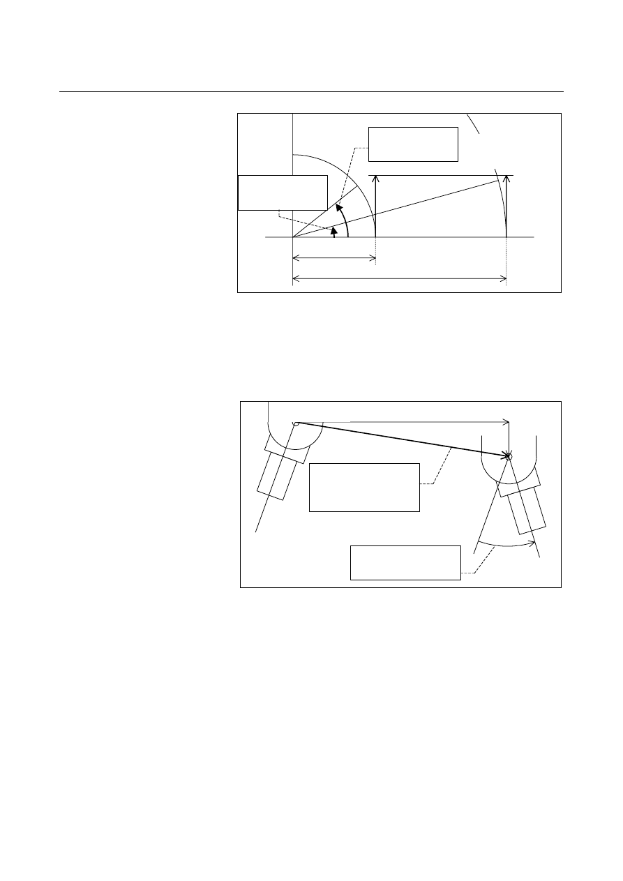
10mm

36mm

Instruction feedrate 

F=10mm/min


Rotation feedrate when

36mm setting.:(2)


Rotation feedrate when 

10mm setting.:(1)


Fig. 5.5 (a) 


 - Example 2 

When a machine into which direction of a tool changes by a rotary 
axis like Fig2, movement feedrate of a standard point can be assumed 
to be instruction feedrate F by making this function effective and 
setting 0 in imaginary radius(parameter No.1465) . 


The feedrate element of a rotary 

axis is excluded. 

The movement feedrate of a 

standard point becomes 

instruction feedrate F. 

Standard point 


Fig. 5.5 (b) 


B-63944EN/03

 PROGRAMMING 

5.FEED FUNCTIONS


- 173 - 

Limitation 

This function corresponds only the linear interpolation(G01). 
However, it doesn't correspond to the following functions. 


Inverse time feed 


Feed per revolution 


Normal direction control 


High-speed cycle cutting 

 Cylindrical 

interpolation 


Polar coordinate interpolation 


Tool center point control for 5-axis machining 


Axis control by PMC 


Manual numerical command 

In this function, in case of using the parallel axis control and the twin 
table control, an imaginary radius parameter(No.1465) specifies the 
same value with a master axis and a slave axis. 
 

NOTE 

1  When the parameter ROTx (No.1006#0) and the 

parameter RFDx (No.1408#0) are 1, this function 
becomes effective. 

2  The parameter RFDx (No.1408#0) and an 

imaginary radius (parameter No.1465) of this 
function can be rewriting by the programable 
parameter input(G10). 

3  It moves at the maximum cutting feedrate when 

this function effectively and sets 0 in an imaginary 
radius (parameter No.1465) and it instructs only a 
rotary axis. 

4  Note setting RFDx (No.1408#0) and an imaginary 

radius (parameter No.1465) enough. Especially, a 
movement of axis quickens compared with this 
function unused when small value is set to an 
imaginary radius. 

5  In this function, the same value as the parameter 

value (No.1408, No.1465) of a master axis is used 
with a slave axis, when it uses axis synchronous 
control. 


5.FEED FUNCTIONS

 PROGRAMMING 

B-63944EN/03


- 174 - 

5.6 

DWELL 


Format 

M


G04 X_; or G04 P_; 

X_ : Specify a time or spindle speed (decimal point permitted)
P_ : Specify a time or spindle speed (decimal point not 

permitted) 


T


G04 X_ ; or G04 U_ ; or G04 P_ ; 

X_ : Specify a time or spindle speed (decimal point permitted)
U_ : Specify a time or spindle speed (decimal point permitted)
P_ : Specify a time or spindle speed (decimal point not 

permitted) 


Explanation 

By specifying a dwell, the execution of the next block is delayed by 
the specified time.    (Dwell per second) 
By setting bit 1 (DWL) of parameter No. 3405 in the feed per 
revolution mode, the execution of the next block is delayed until the 
rotation count of the spindle reaches the specified number.  (Dwell 
per revolution) 


Table 5.6 (a) Command value range of the dwell time (Command by X or U)

Increment system 

Command value range 

Dwell time unit 

IS-A 

0.01 to 999999.99 

IS-B 

0.001 to 99999.999 

IS-C 

0.0001 to 9999.9999 

IS-D 

0.00001 to 999.99999 

IS-E 

0.000001 to 99.999999 

s or rev 


Table 5.6 (b)    Command value range of the dwell time (Command by P) 

Increment system 

Command value range 

Dwell time unit 

IS-A 

1 to 99999999 

0.01 s or rev 

IS-B 

1 to 99999999 

0.001 s or rev 

IS-C 

1 to 99999999 

0.0001 s or rev 

IS-D 

1 to 99999999 

0.00001 s or rev 

IS-E 

1 to 99999999 

0.000001 s or rev


B-63944EN/03

 PROGRAMMING 

5.FEED FUNCTIONS


- 175 - 

In the case of dwell per second, the specification unit for dwell time 
specified with P can be fixed at 0.001 second by setting bit 7 (DWT) 
of parameter No. 1015 to 1. 
 

NOTE 

1  When X, U, or P is specified without a decimal 

point, the specification unit does not depend on 
inch/metric input.    Depending on whether the 
X-axis is present, the following increment system is 
used: 

  When the X-axis is present 

The increment system of the X-axis is used. 

  When the X-axis is not present 

The increment system of the reference axis is 
used. 

2  When P is specified, bit 7 (IPR) of parameter No. 

1004 exercises no influence. 


M


Specify dwell also to make an exact check in the cutting mode (G64 
mode). 
If the specification of P and X is omitted, an exact stop occurs. 


6.REFERENCE POSITION

 PROGRAMMING 

B-63944EN/03


- 176 - 

REFERENCE POSITION 

 
A CNC machine tool has a special position where, generally, the tool 
is exchanged or the coordinate system is set, as described later. This 
position is referred to as a reference position. 
 
Chapter 6, "REFERENCE POSITION", consists of the following 
sections: 
 
6.1  REFERENCE POSITION RETURN........................................177 
6.2  FLOATING REFERENCE POSITION RETURN (G30.1) .....184 
 

B-63944EN/03

 PROGRAMMING 

6.REFERENCE POSITION


- 177 - 

6.1 

REFERENCE POSITION RETURN 


Overview 
 - Reference position 

The reference position is a fixed position on a machine tool to which 
the tool can easily be moved by the reference position return function. 
For example, the reference position is used as a position at which tools 
are automatically changed.  Up to four reference positions can be 
specified by setting coordinates in the machine coordinate system in 
parameters (No. 1240 to 1243). 

Reference position 

Machine zero point 

3rd reference position 

2nd reference position 

4th reference 
position 

Y


Fig. 6.1 (a)    Machine zero point and reference positions 


  - Automatic reference position return (G28) and movement from the reference 

position (G29) 

The automatic reference position return (G28) function returns tools 
automatically to the reference position via an intermediate position 
along a specified axis.    When reference position return is completed, 
the lamp for indicating the completion of reference position return 
goes on.  The return from reference position (G29) function moves 
tools from the reference position to a specified position via an 
intermediate position along a specified axis. 

A (Start position for reference 
position return) 

C (Destination of return from 
the reference position) 

R (Reference position) 

Automatic reference position return (G28)
 A 

 B 

 R 

Movement from the reference position (G29)
 R 

 B 

 C 

B (Intermediate 
position) 


Fig. 6.1 (b)    Reference position return and return form the reference 

position


6.REFERENCE POSITION

 PROGRAMMING 

B-63944EN/03


- 178 - 

  - Reference position return check (G27) 

The reference position return check (G27) is the function which 
checks whether the tool has correctly returned to the reference 
position as specified in the program.  If the tool has correctly 
returned to the reference position along a specified axis, the lamp for 
the axis for indicating the completion of reference position return goes 
on. 
If the tool has not reached the reference position, an alarm (PS0092) 
"ZERO RETURN CHECK (G27) ERROR" is issued. 
When no movement was made along the axis, whether the current 
position is the reference position is checked. 
 

Format 
  - Automatic reference position return and 2nd/3rd/4th reference position return 

G28 

IP

_; 

Reference position return


G30 P2 

IP

_; 

2nd reference position return (P2 can be 
omitted.)


G30 P3 

IP

_; 

3rd reference position return


G30 P4 

IP

_; 

4th reference position return


IP 

:  Specify the intermediate position in the absolute 

coordinate system. 

 (absolute/incremental 

programming) 

There is no need to calculate an actual travel distance 
between the intermediate position and the reference 
position. 


  - Movement from reference position 

G29 

IP

_; 

IP 

:  Specify the destination of return from the reference 

position in the absolute coordinate system. 
(absolute/incremental programming) 


The intermediate position is determined by G28, G30, or 
G30.1 specified immediately before this command. 


  - Reference position return check 

G27 

IP

_; 

IP 

:  Specify positioning to the reference position in the 

absolute coordinate system so as to return to the 
reference position. (absolute/incremental programming) 


B-63944EN/03

 PROGRAMMING 

6.REFERENCE POSITION


- 179 - 

Explanation 
  - Automatic reference position return (G28) 

Positioning to the intermediate or reference positions are performed at 
the rapid traverse rate of each axis. 
Therefore, for safety, the compensation functions, such as the tool 
radius compensation and tool length compensation, should be 
cancelled before executing this command. 
The coordinates for the intermediate position are stored in the CNC 
for the axes for which a value is specified in a G28 block.    For the 
other axes, the previously specified coordinates are used.   
 
(Example) 
 

N1 G28 X40.0 ; 


(The tool moves to the reference position along the X-axis and 
the intermediate position (X40.0) is stored.) 


N2 G28 Y60.0 ; 


(The tool moves to the reference position along the Y-axis and 
the intermediate position (Y60.0) is stored.) 


N3 G29 X10.0 Y20.0 ; 


(The tool moves to the position specified with G29 via the 
intermediate position (X40.0 Y60.0) previously specified with 
G28 along the X-axis and Y-axis.) 


  - 2nd, 3rd, and 4th reference position return (G30) 

The 2nd, 3rd, and 4th reference position return (G30) function can be 
used after the reference positions are established. 
The G30 command is generally used when the automatic tool changer 
(ATC) position differs from the reference position. 
 

  - Movement from the reference position (G29) 

This function is executed after the tool is returned to the reference 
position by G28 or G30. 
For incremental programming, the command value specifies the 
incremental value from the intermediate point. 
The tool moves to the intermediate and specified positions at the 
feedrate specified with a parameter. 
When the workpiece coordinate system is changed after the tool 
reaches the    reference position through the intermediate point by the 
G28 command, the intermediate point also shifts to a new coordinate 
system.  If G29 is then commanded, the tool moves to the 
commanded position through the intermediate point which has been 
shifted to the new coordinate system. 
The same operations are performed also for G30 and G30.1 
commands. 
After the power is turned on, an alarm (PS0305) is issued if an attempt 
is made to execute G29 (movement from the reference position) 
before G28 (automatic reference position return), G30 (2nd, 3rd, and 
4th reference position return), or G30.1 (floating reference position 
return) is executed. 


Content      ..     25      26      27      28     ..