FANUC Series 30i/300i/300is-MODEL A. Machining Center System. User's manual - page 25
 

  Index      Manuals     FANUC Series 30i/300i/300is-MODEL A. Machining Center System. User's manual (B-63944EN/03)


Search            copyright infringement  


Content      ..     23      24      25      26     ..


FANUC Series 30i/300i/300is-MODEL A. Machining Center System. User's manual - page 25


5.FEED FUNCTIONS

 PROGRAMMING 

B-63944EN/03


- 156 - 

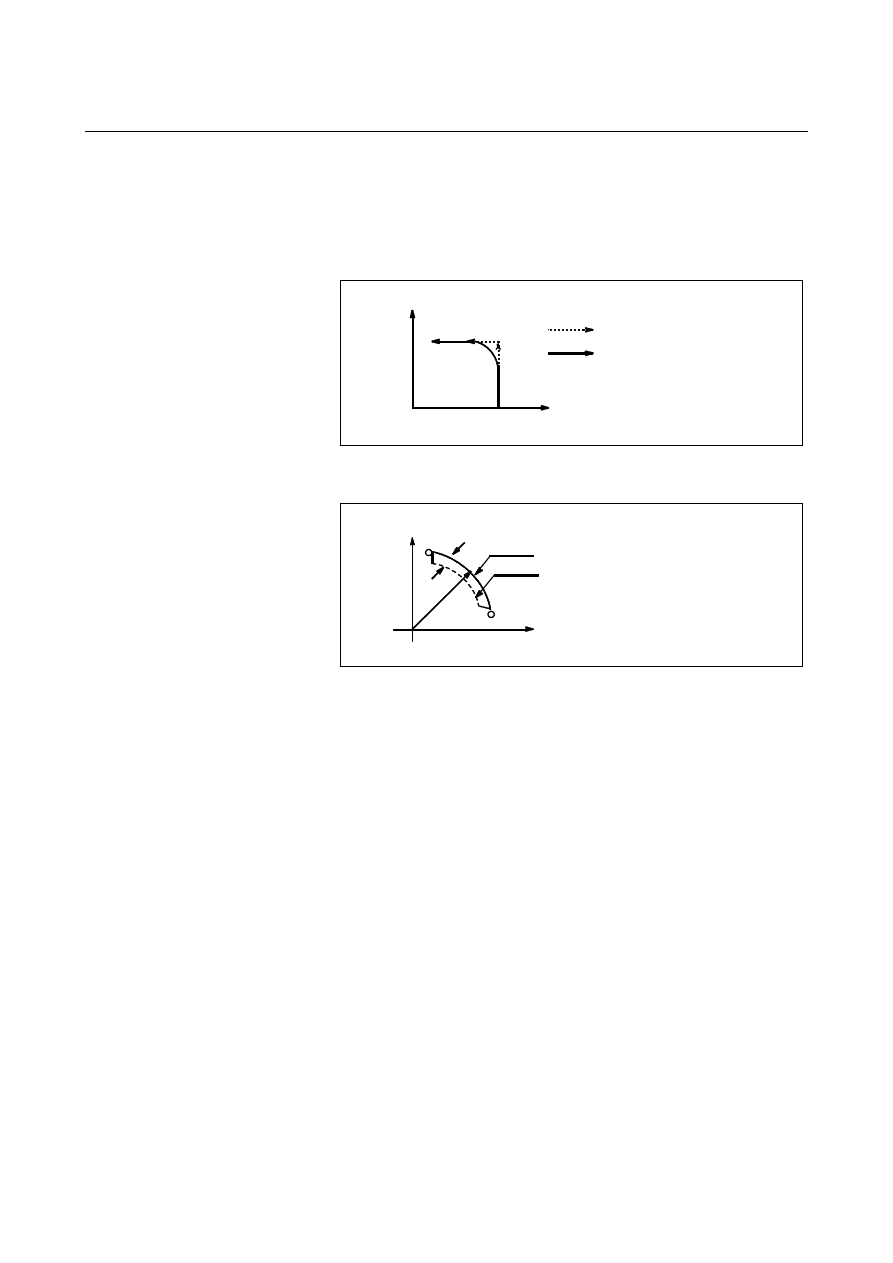
  - Tool path in a cutting feed 

When the movement direction changes between a specified block and 
the next block during cutting feed, the tool path may be rounded 
because of the relationship between the time constant and feedrate 
(Fig. 5.1(b)). 
 

0

Programmed path
Actual tool path

Y

X


Fig. 5.1 (b)    Example of tool path between two blocks   

 
In circular interpolation, a radial error occurs (Fig. 5.1(c)). 


0

Y

X

r


r : Error

Programmed path 

Actual tool path 


Fig. 5.1 (c)    Example of radial error in circular interpolation 


The rounded-corner path shown in Fig. 5.1(b) and the error shown in 
Fig. 5.1 (c) depend on the feedrate. So, the feedrate needs to be 
controlled for the tool to move as programmed. 
 

B-63944EN/03

 PROGRAMMING 

5.FEED FUNCTIONS


- 157 - 

5.2 

RAPID TRAVERSE 


Format 

G00 

IP_ 

;


G00  : G code (group 01) for positioning (rapid traverse) 

IP

_  : Dimension word for the end point 


Explanation 

The positioning command (G00) positions the tool by rapid traverse.   
In rapid traverse, the next block is executed after the specified feedrate 
becomes 0 and the servo motor reaches a certain range set by the 
machine tool builder (in-position check). 
A rapid traverse rate is set for each axis by parameter No. 1420, so no 
rapid traverse feedrate need be programmed. 
The following overrides can be applied to a rapid traverse rate with 
the switch on the machine operator's panel:F0, 25%, 50%, 100% 
F0: Allows a fixed feedrate to be set for each axis by parameter No. 
1421. 
For detailed information, refer to the appropriate manual of the 
machine tool builder. 


5.FEED FUNCTIONS

 PROGRAMMING 

B-63944EN/03


- 158 - 

5.3 

CUTTING FEED 


Overview 

Feedrate of linear interpolation (G01), circular interpolation (G02, 
G03), etc. are commanded with numbers after the F code. 
In cutting feed, the next block is executed so that the feedrate change 
from the previous block is minimized. 
 

M


Four modes of specification are available: 
1.  Feed per minute (G94) 
 

After F, specify the amount of feed of the tool per minute. 

2.  Feed per revolution (G95) 
 

After F, specify the amount of feed of the tool per spindle 
revolution. 

3.  Inverse time feed (G93) 
 

Specify the inverse time (FRN) after F. 

4.  One-digit F code feed 
 

Specify a desired one-digit number after F. Then, the feedrate set 
with the CNC for that number is set. 

T


Two modes of specification are available: 
1.  Feed per minute (G98) 
 

After F, specify the amount of feed of the tool per minute. 

2.  Feed per revolution (G99) 
 

After F, specify the amount of feed of the tool per spindle 
revolution. 

3.  Inverse time feed (G93) 
 

Specify the inverse time (FRN) after F. 


Format 

M


Feed per minute 

G94 ; 

G code (group 05) for feed per minute


F_ ; 

Feedrate command (mm/min or inch/min)


Feed per revolution 

G95 ; 

G code (group 05) for feed per revolution


F_ ; 

Feedrate command (mm/rev or inch/rev)


Inverse time feed (G93) 

G93 ; 

Inverse time feed command G code (05 group)


F_ ; 

Feedrate command (1/min)


One-digit F code feed 

Fn ; 

 n : 

Number from 1 to 9


B-63944EN/03

 PROGRAMMING 

5.FEED FUNCTIONS


- 159 - 

T


Feed per minute 

G98 ; 

G code (group 05) for feed per minute


F_ ; 

Feedrate command (mm/min or inch/min)


Feed per revolution 

G99 ; 

G code (group 05) for feed per revolution


F_ ; 

Feedrate command (mm/rev or inch/rev) 

Inverse time feed (G93) 

G93 ; 

Inverse time feed command G code (05 group)


F_ ; 

Feedrate command (1/min)


Explanation 
  - Direction of the cutting feedrate 

Cutting feed is controlled so that the tangential feedrate is always set 
at a specified feedrate. 

X

End point

Start

point

X

F

F

Center

End

Start

point

Linear interpolation

Circular interpolation

Y

Y


Fig. 5.3 (a)    Tangential feedrate (F) 


  - Feed per minute 

After specifying G code for feed per minute (in the feed per minute 
mode), the amount of feed of the tool per minute is to be directly 
specified by setting a number after F. G code for feed per minute is a 
modal code. Once a G code for feed per minute is specified, it is valid 
until G code for feed per revolution (feed per revolution) is specified.     
 

M


At power-on, the feed per minute mode is set. 
 

T


At power-on, the feed per revolution mode is set. 


An override from 0% to 254% (in 1% steps) can be applied to feed per 
minute with the switch on the machine operator's panel. For detailed 
information, see the appropriate manual of the machine tool builder. 

5.FEED FUNCTIONS

 PROGRAMMING 

B-63944EN/03


- 160 - 


For milling machining 

Workpiece

Table

Tool

Feed amount per minute

(mm/min or inch/min)


For lathe cutting 


Feed amount per minute 

(mm/min or Íinch/min) 

F


  Fig. 5.3 (b)    Feed per minute 


 CAUTION 


No override can be used for some commands such 
as for threading. 


  - Feed per revolution 

After specifying G code for feed per revolution (in the feed per 
revolution mode), the amount of feed of the tool per spindle revolution 
is to be directly specified by setting a number after F.  G code for 
feed per revolution is a modal code. Once a G code for feed per 
revolution is specified, it is valid until G code for feed per minute 
(feed per minute) is specified.   
An override from 0% to 254% (in 1% steps) can be applied to feed per 
revolution with the switch on the machine operator's panel.  For 
detailed information, see the appropriate manual of the machine tool 
builder. 
 

T


If bit 0 (NPC) of parameter No. 1402 has been set to 1, feed per 
revolution commands can be specified even when a position coder is 
not being used. (The CNC converts feed per revolution commands to 
feed per minute commands.) 

B-63944EN/03

 PROGRAMMING 

5.FEED FUNCTIONS


- 161 - 


For milling machining 

F

Feed amount per spindle
revolution (mm/rev or inch/rev)


For lathe cutting 

Feed amount per spindle revolution

(mm/rev or inch/rev)

F


Fig. 5.3 (c)    Feed per revolution 


 CAUTION 


When the speed of the spindle is low, feedrate 
fluctuation may occur.   


The slower the spindle rotates, the more frequently 
feedrate fluctuation occurs. 


  - Inverse time feed 

When G code for inverse time feed is specified, the inverse time 
specification mode (G93 mode) is set.  Specify the inverse time 
(FRN) with an F code. 
A value from 0.001 to 9999.999 can be specified as FRN, regardless 
of whether the input mode is inches or metric, or the increment system 
is IS-B or IS-C. 

F code specification value 

FRN 

F1 0.001 
F1  

(*1)

 1.000 

F1.0 1.000 
F9999999 9999.999 
F9999  

(*1)

 9999.000 

F9999.999 9999.999 


NOTE 

*1  Value specified in fixed-point format with bit 0 (DPI) 

of parameter No. 3401 set to 1 


5.FEED FUNCTIONS

 PROGRAMMING 

B-63944EN/03


- 162 - 

G code for inverse time feed is a modal G code and belongs to group 
05 (includes G code for feed per revolution and G code for feed per 
minute). 
When an F value is specified in inverse time specification mode and 
the feedrate exceeds the maximum cutting feedrate, the feedrate is 
clamped to the maximum cutting feedrate. 
In the case of circular interpolation, the feedrate is calculated not from 
the actual amount of movement in the block but from the arc radius. 
This means that actual machining time is longer when the arc radius is 
longer than the arc distance and shorter when the arc radius is shorter 
than the arc distance. Inverse time feed can also be used for cutting 
feed in a canned cycle. 
 

NOTE 

1  In the inverse time specification mode, an F code is 

not handled as a modal code and therefore needs 
to be specified in each block. If an F code is not 
specified, alarm PS0011 (FEED ZERO 
(COMMAND)) is issued. 

2  When F0 is specified in inverse time specification 

mode, alarm PS0011 (FEED ZERO (COMMAND)) 
is issued. 

3  Inverse time feed cannot be used when PMC axis 

control is in effect. 

4  If the calculated cutting feedrate is smaller than the 

allowable range, alarm PS0011 (FEED ZERO 
(COMMAND)) is issued. 


Example 


For linear interpolation (G01) 


distance

feedrate

time(min)

1

FRN

=

=


Feedrate: 

mm/min  (for metric input) 


inch/min (for inch input) 


Distance: 

mm 


(for metric input) 


inch 


(for inch input) 


To end a block in 1 (min) 


1

(min)

1

1

(min)

1

=

=

=

time

FRN


 Specify 

F1.0. 

To end a block in 10 (sec) 


6

(sec)

60

/

10

1

60

/

(sec)

1

=

=

=

time

FRN


 Specify 

F6.0. 

To find the movement time required when F0.5 is specified 


2

5

.

0

1

1

(min)

=

=

=

FRN

TIME


2 (min) is required. 

B-63944EN/03

 PROGRAMMING 

5.FEED FUNCTIONS


- 163 - 

-  To find the movement time required when F10.0 is 

specified 


6

10

60

60

1

(min)

=

=

×

=

FRN

TIME


6 (sec) is required. 


For circular interpolation (G02, G03) 


arcradius

feedrate

time

FRN

=

=

(min)

1


Feedrate:   

mm/min  (for metric input) 

    inch/min 

(for 

inch 

input) 


Arc radius:  mm 

(for metric input) 

    inch (for 

inch 

input) 


NOTE 

In the case of circular interpolation, the feedrate is 

calculated not from the actual amount of movement 
in the block but from the arcadias. 


  - One-digit F code feed 

M


When a one-digit number from 1 to 9 is specified after F, the feedrate 
set for that number in a parameter Nos. 1451 to 1459 is used.    When 
F0 is specified, the rapid traverse rate is applied. 
The feedrate corresponding to the number currently selected can be 
increased or decreased by turning on the switch for changing one-digit 
F feedrate on the machine operator's panel, then by rotating the 
manual pulse generator. 
The increment/decrement, 

F, in feedrate per scale of the manual 

pulse generator is as follows: 

X

F

F

100

max

=


Fmax 

: Feedrate upper limit for F1-F4 set by parameter 

(No.1460), or feedrate upper limit for F5-F9 set by 
parameter (No.1461) 

: Any value of 1-127 set by parameter No.1450 

The feedrate set or altered is kept even while the power is off. The 
current feed rate is displayed on the LCD screen. 


  - Cutting feedrate clamp 

Parameter No. 1430 can be used to specify the maximum cutting 
feedrate for each axis. When the cutting feedrate along an axis 
exceeds the maximum feedrate for the axis as a result of interpolation, 
the cutting feedrate is clamped to the maximum feedrate. 
 

Reference 

See Appendix D for range of feedrate command value.   


Content      ..     23      24      25      26     ..