FANUC Series 30i/300i/300is-MODEL A. Machining Center System. User's manual - page 24
 

  Index      Manuals     FANUC Series 30i/300i/300is-MODEL A. Machining Center System. User's manual (B-63944EN/03)


Search            copyright infringement  


Content      ..     22      23      24      25     ..


FANUC Series 30i/300i/300is-MODEL A. Machining Center System. User's manual - page 24


4.INTERPOLATION FUNCTIONS

 PROGRAMMING 

B-63944EN/03


- 148 - 


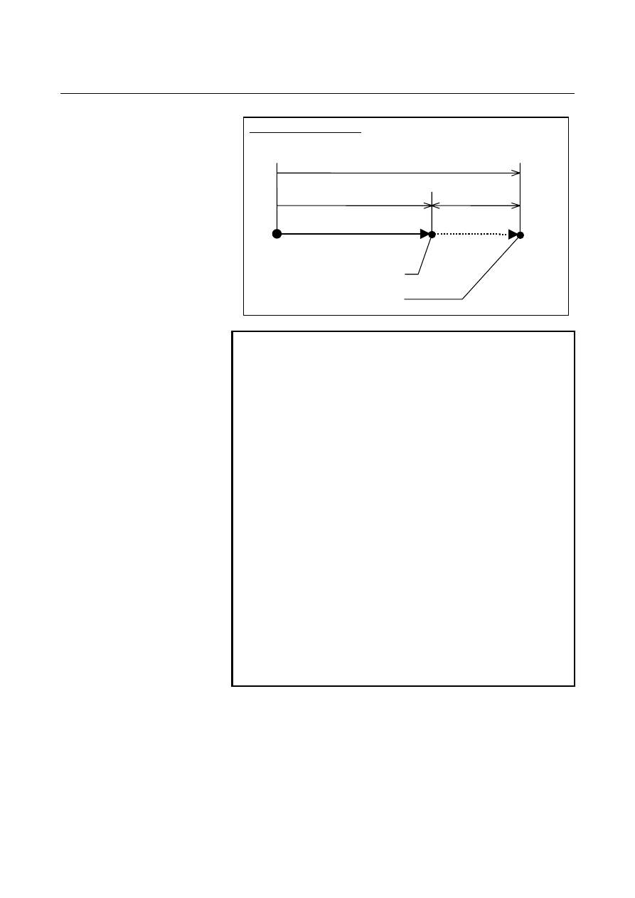
Position during a skip operation 

Current position of the CNC


Machine position 

Error 

Position compensated for by 
reflecting the delay 

Position not reflecting the delay

Coordinate origin 

Stop point 


NOTE 

1  Specify only a single axis with the torque limit skip 

command. If no axis is specified or an attempt is 
made to specify more than one, alarm PS0369 is 
issued. 

2  Do not issue the torque limit skip command in 

3-dimensional coordinate conversion mode or to a 
parallel axis. Otherwise, alarm PS0035 is issued. 

3  Do not issue the torque limit skip command in G41 or 

G42 mode. Otherwise, alarm PS0035 is issued. 

4  A torque limit arrival signal is output regardless of the 

torque limit skip command. 

5  Do not issue the torque limit skip command for an 

axis being synchronized with synchronization control 
(such as synchronization control, twin table control, 
or electronic gear box). 

6  Do not specify the torque limit skip command in a 

continuous block. 

7  The higher the movement speed, the larger the error 

between the position at which the machine stops and 
the position at which a skip is actually detected. Also, 
the error increases as the speed is varied during 
movement. Do not vary the speed with override and 
so on. 


B-63944EN/03

 PROGRAMMING 

4.INTERPOLATION FUNCTIONS


- 149 - 

4.23 

THREE-DIMENSIONAL CIRCULAR INTERPOLATION 


Overview 

Specifying an intermediate and end point on an arc enables circular 
interpolation in a 3-dimensional space. 
 

Format 

The command format is as follows:


G02.4 X

X1

 Y

Y1

 Z

Z1


α

α

1

 β

β

1

 ; 

First block (mid-point of the 
arc)


            X

X2

 Y

Y2

 Z

Z2


α

α

2

 β

β

2

 ; 

Second block (end point of 
the arc)


α,β : 


Arbitrary axes other than the 3-dimensional circular 
interpolation axis (up to two axes) 
To be specified if necessary. 

G03.4 can also be specified instead of G02.4.     
G03.4 performs the same operation as G02.4. 


Explanation 
  - G code group 

G02.4 and G03.4 are modal G codes of group 01. They therefore 
remain effective until another G code in group 01 is specified.   
 

  - Start point, mid-point, and end point 

An arc in a 3-dimensional space is uniquely defined with its start point 
(current position) and a specified intermediate point and end point, as 
shown below. Two command blocks are used to define this arc. The 
first command block specifies the tool path between the start point and 
intermediate point. The second command block specifies the tool path 
between the intermediate point and end point.   

X

Y

Z

Start point

Mid-point
(X1,Y1,Z1)

End point
(X2,Y2,Z2)


Fig. 4.23 (a)    Start, Mid, and End Points 

 
If the modal code is changed by specifying a code such as G01 with 
the end point not specified, the arc cannot be obtained, and alarm 
PS5432 is issued. During MDI operation, alarm PS5432 is also issued 
if a cycle start is applied with only the mid-point specified.   
 

4.INTERPOLATION FUNCTIONS

 PROGRAMMING 

B-63944EN/03


- 150 - 

  - Movement along axes other than the three-dimensional circular interpolation axis 

In addition to the three-dimensional circular interpolation axis 
(X/Y/Z), up to two arbitrary axes (

α

/

β

) can be specified at a time. If / 

are omitted from the first block (mid-point specification) and are 
specified only in the second block (end point specification), the tool 
moves to the specified point along the 

α

/

β

 axes during movement 

from the mid-point of the arc to the end point. If 

α

/

β

 are omitted from 

the second block (end point specification) and are specified only in the 
first block (mid-point specification), the tool moves to the specified 
point along the 

α

/

β

 axes during movement from the start point of the 

arc to the mid-point.   
 

 - Incremental programming 

With an incremental programming, the position of the mid-point 
relative to the start point must be specified in the first block, and the 
position of the end point relative to the mid-point must be specified in 
the second block.   
 

  - Direction of rotation 

The direction of rotation cannot be specified. The movement is the 
same regardless of whether G02.4 or G03.4 is specified.   
 

 - Single block 

When operation is performed using a single block, one cycle start 
causes movement from the start point to the end point. A single-block 
stop is not performed between the first block (mid-point specification) 
and the second block (end point specification).   
 

  - Start point assumed if three-dimensional circular interpolations are specified 

consecutively 

If three-dimensional circular interpolations are specified consecutively, 
the end point in one interpolation is assumed to be the start point in 
the next interpolation.   
 

 - Velocity commands 

As the velocity command, specify the tangential velocity along the arc 
in the three-dimensional space. 
 

B-63944EN/03

 PROGRAMMING 

4.INTERPOLATION FUNCTIONS


- 151 - 

Limitation 
  - Cases in which linear interpolation is performed 


f the start point, mid-point, and end-point are on the same line, 
linear interpolation is performed. 


If the start point coincides with the mid-point, the mid-point 
coincides with the end point, or the end point coincides with the 
start point, linear interpolation is performed up to the end point. 


If the start point, mid-point, and end-point are on the same line 
and the end point lies between the start point and the mid-point, 
the tool first moves with linear interpolation from the start point 
to the mid-point, then returns from the mid-point to the end point 
with linear interpolation. Thus, the tool always passes through 
the specified point. 

Start point

Mid-point

End point


 - Whole circles 

A whole circle (360

°

 arc) cannot be specified. (This corresponds to the 

case in which linear interpolation is performed, as described earlier.) 
 

 - Compensation functions 

Before using this function, cancel the compensation functions of 
group 07, such as cutter radius compensation.   
 

 - Manual absolute 

While this function is in use, manual intervention is not possible with 
the manual absolute switch set to the ON position. If intervention is 
performed, alarm PS5433 is issued when operation restarts.   
 

  - Restrictions on commands 

In the three-dimensional circular interpolation mode, the functions 
listed below can be used, but the states of these functions must not be 
modified. 

  Inch input/metric input  (An alarm is issued if a state 

modification is made with G20 or G21.) 


Mirror image    (The state of a signal must not be changed.) 


One-digit F code feed    (No feedrate change must be made using 
the manual handle.) 


 - Unusable commands 

In the three-dimensional circular interpolation mode, the functions 
listed below must not be specified. Otherwise, an alarm is issued. 

 Exponential 

interpolation..............................................G02.3,G03.3 

 Dwell ..........................................................................................G04 

 High-speed 

machining ................................................................G05 

  (Excluding G05P10000 and G05P0) 

  AI contour control ................................................ G05.1Q1,G5.1Q0 

4.INTERPOLATION FUNCTIONS

 PROGRAMMING 

B-63944EN/03


- 152 - 

  Hypothetical axis interpolation...................................................G07 

 Cylindrical 

interpolation..........................................................G07.1 

  Advanced preview control..........................................................G08 

  (Use AI high-precision contour control.) 

  Polar coordinate interpolation.......................................G12.1,G13.1 

  Polar coordinate command .................................................G15,G16 

  Reference position return check .................................................G27 

  Reference position return............................................................G28 

  2nd reference position return ......................................................G30 

  3rd, 4th reference position return................................................G30 

 Skip.............................................................................................G31 

 Threading....................................................................................G33 

  Automatic tool length measurement ...........................................G37 

  3-dimensional cutter compensation ............................................G41 

 Tool 

offset........................................................... G45,G46,G47,G48 

  Programmable mirror image.........................................G50.1,G51.1 

  Local coordinate system .............................................................G52 

 Machine 

coordinate system ........................................................G53 

  Single direction positioning........................................................G60 

 Tapping 

mode .............................................................................G63 

  Macro call (Subprogram call is possible.) .................. G65,G66,G67 

 Figure 

copying..............................................................G72.1,G72.2 

 Canned 

cycle...............................G73-G79,G80,G81-G89,G98,G99 

 Workpiece 

coordinate 

system setting .........................................G92 

 Workpiece 

coordinate 

system preset .......................................G92.1 

  Feed per revolution .....................................................................G95 

  Constant surface speed control ...........................................G96,G97 

 NURBS 

interpolation...............................................................G06.2 

  Workpiece coordinate system setting ......................G54-G59,G54.1 

 3-dimensional 

coordinate system conversion .............................G68 

  Coordinate system rotation .........................................................G68 

 Scaling ................................................................................G50,G51 

  Programmable mirror image.........................................G50.1,G51.1 

  Exact stop mode..........................................................................G61 

  Tool radius/tool nose radius compensation G38,G39,G40,G41,G42 

  3-dimensional cutter compensation ....... G40, G41.2, G41.3, G41.4, 

..................................... G41.5, G41.6, G42.2, G42.4, G42.5, G42.6 

 Data 

setting .................................................................................G10 

 Exact 

stop ...................................................................................G09 

 Auxiliary 

function 

  2nd auxiliary function 

 Spindle 

function 

 Tool 

function 


B-63944EN/03

 PROGRAMMING 

4.INTERPOLATION FUNCTIONS


- 153 - 

 - Unusable functions 

If the following function is specified in the three-dimensional circular 
interpolation mode, a warning is output: 

 MDI 

intervention 

If any of the following functions is specified in the three-dimensional 
circular interpolation mode, the alarm (PS5196) is issued: 

  Manual operation interrupt 

  Tool retract and recover 

In the three-dimensional circular interpolation mode, the following 
functions cannot be used: 

  Sequence number comparison and stop    (Stop operation cannot be 

performed with a sequence number in the three-dimensional 
circular interpolation mode.)   

  Index table indexing 

  Rotary axis control 

  Macro executor  (Execution macro) 

  Manual handle interruption 

  Optional chamfering/corner R 


- Other limitations 

When the following function is used, three-dimensional circular 
interpolation cannot be used:   

  Arbitrary angular axis control 

A limitation may be imposed on other NC command combinations.  
See the description of each function. 
 

5.FEED FUNCTIONS

 PROGRAMMING 

B-63944EN/03


- 154 - 

FEED FUNCTIONS 

 
Chapter 5, "FEED FUNCTIONS", consists of the following sections: 
 
5.1 OVERVIEW .............................................................................155 
5.2 RAPID TRAVERSE .................................................................157 
5.3 CUTTING FEED ......................................................................158 
5.4  CUTTING FEEDRATE CONTROL ........................................164 
5.5  FEEDRATE INSTRUCTION ON IMAGINARY CIRCLE   

FOR A ROTARY AXIS ...........................................................169 

5.6 DWELL.....................................................................................174 
 

B-63944EN/03

 PROGRAMMING 

5.FEED FUNCTIONS


- 155 - 

5.1 

OVERVIEW 

 
The feed functions control the feedrate of the tool. The following two 
feed functions are available: 
 

 - Feed functions 

1. Rapid 

traverse 


When the positioning command (G00) is specified, the tool 
moves at a rapid traverse feedrate set in the CNC (parameter No. 
1420). 

2. Cutting 

feed 


The tool moves at a programmed cutting feedrate. 


 - Override 

Override can be applied to a rapid traverse rate or cutting feedrate 
using the switch on the machine operator's panel. 
 

 - Automatic acceleration/deceleration 

To prevent a mechanical shock, acceleration/deceleration is 
automatically applied when the tool starts and ends its movement (Fig. 
5.1(a)). 

Rapid traverse rate

F

R

 : Rapid traverse

rate

T

R

 : Deceleration time

constant for rapid

traverse rate

0

Time

0

Feedrate

F

R

T

R

T

R

F

C

T

C

T

C

F

C

 : Feedrate

T

C

 : Acceleration/

deceleration time
constant for a
cutting feedrate

Time


Fig. 5.1 (a)    Automatic acceleration/deceleration (example) 


Content      ..     22      23      24      25     ..