FANUC Series 30i/300i/300is-MODEL A. Machining Center System. User's manual - page 20
 

  Index      Manuals     FANUC Series 30i/300i/300is-MODEL A. Machining Center System. User's manual (B-63944EN/03)


Search            copyright infringement  


Content      ..     18      19      20      21     ..


FANUC Series 30i/300i/300is-MODEL A. Machining Center System. User's manual - page 20


4.INTERPOLATION FUNCTIONS

 PROGRAMMING 

B-63944EN/03


- 116 - 

Explanation 

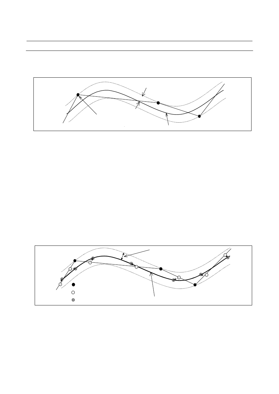
Generally, a program approximates a sculptured surface with minute 
segments with a tolerance of about 10 

µ

m. 


Tolerance

Programmed point

Desired curve


Many programmed points are placed on the boundary of tolerance.  
The programmed points also have a rounding error owing to the least 
input increment of the CNC. The nano smoothing function creates 
multiple insertion points between adjacent programmed points so that 
a smooth curve can be created from the approximation segments.  
The desired curve is inferred from the insertion points of multiple 
blocks including buffered blocks. 
 
Many insertion points are closer to the desired curve than the 
programmed points. A stable curve can be inferred with the insertion 
points created from multiple blocks including buffered blocks.  
Because the position of each insertion point is corrected in a unit 
smaller than the least input increment of the CNC within tolerance, the 
impact of rounding error is reduced. 
Nano-interpolation is performed for the curve inferred from the 
corrected insertion points, so the resultant cutting surface becomes 
smooth. 
 

Programmed point

Insertion point

Corrected insertion point

Inferred curve

Tolerance


  - Specifying the tolerance 

The tolerance of the program of nano smoothing is specified in 
parameter No. 19581. 
The insertion points are corrected within tolerance, and a curve is 
inferred accordingly. 
If 0 is specified in parameter No. 19581, the minimum travel distance 
in the increment system is considered to be the tolerance. 
 

B-63944EN/03

 PROGRAMMING 

4.INTERPOLATION FUNCTIONS


- 117 - 

  - Nano smoothing 2 

Nano smoothing 2 performs smooth interpolation for the basic three 
axes (or their parallel axes) and two rotation axes independently. 


: Command point

Smoothing on XYZ space


: Command point

Smoothing on BC space


Z

B

C

G5.1 Q3 X0 Y0 Z0 B0 C0;

X_ Y_ Z_ B_ C_; 

X_ Y_ Z_ B_ C_; 

… 

G5.1 Q0;


Insertion points for the rotation axes are corrected so that each axis 
element of the distance between an insertion point and the corrected 
insertion point for both axes does not exceed the tolerance set for each 
axis in parameter No. 19587. 


Tolerance

for C-axis

Tolerance for 

B-axis

Insertion point should be 
corrected within 
tolerance for each axis 

Insertion point 

Corrected insertion point


B

C

Inferred curve


  - Making a decision on the basis of the spacing between adjacent programmed 

points 

If the spacing between adjacent programmed points (block length) 
exceeds the value specified in parameter No. 8486 or falls below the 
value specified in parameter No. 8490 in the nano smoothing mode, 
the nano smoothing mode is cancelled at the start point of the block.   
Linear interpolation can be performed in the block. 
When a decision is made on the basis of the spacing between adjacent 
programmed points, only the basic three axes (or their parallel axes) 
are considered, and the rotation axes are excluded. When the nano 
smoothing mode is canceled in a block, nano smoothing for the 
rotation axes is not performed, either. 
If the values specified in the parameters are 0, no decision is made on 
the basis of the spacing between adjacent programmed points. 
 

4.INTERPOLATION FUNCTIONS

 PROGRAMMING 

B-63944EN/03


- 118 - 

  - Making a decision at a corner 

If the difference in angle (see the following figure) between adjacent 
programmed blocks exceeds the value specified in parameter No. 
8487 in the nano smoothing mode, the nano smoothing mode is 
cancelled at the corner. 
The decision at the corner is made by considering the basic three axes 
(or their parallel axes) only; the rotation axes are not considered.  
When the nano smoothing mode is canceled in a block, nano 
smoothing for the rotation axes is not performed, either. 


N1 

N2


N3


θ

1


θ

2


θ

1:    Difference in angle between blocks N1 and N2 

θ

2:    Difference in angle between blocks N2 and N3 


If the value specified in the parameter is 0, no decision is made at the 
corner on the basis of the difference in angle. 
Very minute blocks created for some reasons such as a calculation 
error of CAM can be ignored, and a smooth connection can be made 
at a corner. To do this, specify parameter No. 19582 to the minimum 
travel distance with which a decision is made on the basis of 
difference in angle. Then, the decision at a corner is disabled for a 
block of which distance is less than the specified minimum travel 
distance. 
 
However, a decision based on the spacing between adjacent 
programmed points specified in parameter No. 8490 has higher 
priority than the decision at a corner. Therefore, the value specified in 
parameter No. 19582 must be greater than the value specified in 
parameter No. 8490. 

If parameter No. 19582 is specified, a very minute block is not
considered to be a corner, and a smooth connection can be made.


Limitation 
 - Single-block operation 

When single-block operation is carried out in the nano smoothing 
mode, the operation stops at a corrected insertion point not at a 
programmed point. 
Even in the nano smoothing mode, normal single-block operation is 
carried out for a block that does not satisfy the conditions of nano 
smoothing mode. 
 

B-63944EN/03

 PROGRAMMING 

4.INTERPOLATION FUNCTIONS


- 119 - 

  - Tool length compensation 

To carry out tool length compensation, specify the command before 
specifying nano smoothing. Avoid changing the amount of 
compensation in the nano smoothing mode. 
If G43, G44, or G49 is specified in a block between the block in 
which the command of nano smoothing mode on (G5.1 Q3) is 
specified and the block in which the command of nano smoothing 
mode off (G5.1 Q0) is specified, an alarm PS0343 will be issued. 
 

  - Tool radius/tool nose radius compensation 

If tool radius/tool nose radius compensation is specified in the nano 
smoothing mode, the nano smoothing mode is cancelled. Then, when 
the command of tool radius/tool nose radius compensation cancel 
(G40) is specified, a decision is made whether to start nano smoothing 
from the next block. The startup and cancel operations of type C are 
always carried out for the tool radius/tool nose radius compensation 
specified in the nano smoothing mode, irrespective of the parameter 
setting. 
A command related to tool radius/tool nose radius compensation 
should not be specified in the nano smoothing mode unless it is 
absolutely necessary. 
 

  - Interruption type custom macro 

No interruption type custom macro can be used in the nano smoothing 
mode. 
If the nano smoothing mode is specified while an interruption type 
custom macro is enabled or if an interruption type custom macro is 
enabled in the nano smoothing mode, an alarm PS0342 will be issued. 
 

 - Manual intervention 

Manual intervention by specifying the manual absolute on command 
cannot be performed in the nano smoothing mode. If this is attempted, 
an alarm PS0340 will be issued at the cycle start after manual 
intervention. 
 

  - Rotary table dynamic fixture offset 

The command of rotary table dynamic fixture offset (G54.2) must be 
cancelled before specifying the nano smoothing mode. These 
commands cannot be used in the nano smoothing mode. If an attempt 
is made to use one of these commands, an alarm PS0343 will be 
issued. 
 

  - Number of blocks that can be specified successively 


Up to about 300,000,000 blocks can be specified successively in the 
nano smoothing mode. If more blocks are specified, an alarm PS0341 
will be issued. 
However, when a block which does not satisfy the conditions of the 
nano smoothing mode is encountered, the mode is canceled and the 
counted number of successive blocks is reset to 0. 
 

4.INTERPOLATION FUNCTIONS

 PROGRAMMING 

B-63944EN/03


- 120 - 

  - Continuity of a program 

Curve interpolation is carried out for multiple programmed blocks 
including buffered blocks in the nano smoothing mode. 
Therefore, the programmed commands must be executed continuously 
in the nano smoothing mode. 
The continuity of a program may be lost, and continuous execution 
may not be performed, in some cases such as the following:  A 
single-block stop is made in the nano smoothing mode; and another 
program is executed in the MDI mode. If this occurs, an alarm PS0344 
will be issued. 
 

  - Restrictions on resumption of automatic operation 

(1) Program 

restart 


Curve interpolation is performed for corrected insertion points 
not for programmed points in the nano smoothing mode.  
Accordingly, when a sequence number is specified to restart the 
program, the operation cannot be restart from a programmed 
point in a block. 


To restart a program, specify a block number, using the block 
counter displayed in the program screen. 

(2) Block 

restart 


A block cannot be restarted in the nano smoothing mode.    When 
an attempt is made to restart a block, an alarm PS0344 will be 
issued. 

(3)  Tool retract and recover 
 

The tool cannot be retracted or recovered in the nano smoothing 
mode. 

(4) Retracing 
 

Retracing cannot be performed in the nano smoothing mode. 

(5)  Active block cancel 
 

The active block cancel function is temporarily disabled in the 
nano smoothing mode. 


  - Functions that cannot be used simultaneously 

The nano smoothing function cannot be used simultaneously with the 
following functions. 

  Parallel axis control 

  Twin table control 


  - Tool center point control 

Nano smoothing 2 can be used with tool center point control (type 1 
(G43.4)). However, when it is used with tool center point control (type 
2 (G43.5)) or tool posture control, alarm PS5421 (ILLEGAL 
COMMAND IN G43.4/G43.5) is issued. 


B-63944EN/03

 PROGRAMMING 

4.INTERPOLATION FUNCTIONS


- 121 - 

4.14 

NURBS INTERPOLATION (G06.2) 

 
Many computer-aided design (CAD) systems used to design metal 
dies for automobiles and airplanes utilize non-uniform rational 
B-spline (NURBS) to express a sculptured surface or curve for the 
metal dies. 
This function enables NURBS curve expression to be directly 
specified to the CNC. This eliminates the need for approximating the 
NURBS curve with minute line segments. This offers the following 
advantages: 
1.  No error due to approximation of a NURBS curve by small line 

segments 

2.  Short part program 
3.  No break between blocks when small blocks are executed at high 

speed 

4.  No need for high-speed transfer from the host computer to the 

CNC 

When this function is used, a computer-aided machining (CAM) 
system creates a NURBS curve according to the NURBS expression 
output from the CAD system, after compensating for the length of the 
tool holder, tool diameter, and other tool elements. The NURBS curve 
is programmed in the NC format by using these three defining 
parameters: control point, weight, and knot. 

CAM (Creating an NC part program)

CAD(Designing a metal die)

Generating a metal die surface
(NURBS surface or curve)

Studying the machining
method and others

Tool compensation file

NC part program after tool compensation
(NURBS curve)

CNC equipment

Machine tool

NURBS curve (control point, weight, knot)


Fig. 4.14 (a)    NC part program for machining a metal die according to a 

NURBS curve 


4.INTERPOLATION FUNCTIONS

 PROGRAMMING 

B-63944EN/03


- 122 - 

NURBS interpolation can be performed for up to five axes (including 
two rotation axes). Therefore, NURBS interpolation can be performed 
for the basic three axes (X, Y, and Z) and two rotation axes at the 
same time. This enables five-axis machining to produce very smooth 
finished surfaces and so finds applications such as machining of 
smooth workpiece side faces. 
In addition, NURBS interpolation can be used with tool center point 
control (type 1 (G43.4)). This eliminates the necessity of modifying a 
program when the tool length is changed. 
 

Format 

G06.2[P ] K X Y Z [

α

 ] [

β

 ][R ] [F ]; 


X Y Z [

α

 ] [

β

 ][R ]; 


X Y Z [

α

 ] [

β

 ][R ]; 


X Y Z [

α

 ] [

β

 ][R ]; 


X Y Z [

α

 ] [

β

 ][R ]; 


G01 . . .


G06.2 :  Start NURBS interpolation mode 
P       :  Rank of NURBS curve 
X Y Z   :  Control  point 

α


β

      :  Control point (rotary axes) 

R       :  Weight 
K       :  Knot 
F       :  Feedrate 

 
If executing NURBS interpolation simultaneously with tool center 
point control (type 1 (G43.4)), enable tool center point control (G43.4) 
first and then enable NURBS interpolation (G06.2). To cancel them, 
end NURBS interpolation (G code command in group 01 other than 
G06.2) first and then cancel tool center point control (G49). 
 
Example : 

O0010 
… 
G43.4 H1 P0; 
G06.2 K_ X_ Y_ Z_ B_ C_; 
… 
K_ 
G01 X_ Y_ Z_ B_ C_; 
G49; 
… 
M30; 

NURBS interpolation 

Tool center point control 


B-63944EN/03

 PROGRAMMING 

4.INTERPOLATION FUNCTIONS


- 123 - 

Explanation 
  - NURBS interpolation mode 

NURBS interpolation mode is selected when G06.2 is programmed. 
G06.2 is a modal G code of group 01. NURBS interpolation mode 
ends when a G code of group 01 other than G06.2 (G00, G01, G02, 
G03, etc.) is specified. 
 

  - Rank of NURBS 

A rank of NURBS can be specified with address P. The rank setting, if 
any, must be specified in the first block. If the rank setting is omitted, 
a rank of four (degree of three) is assumed for NURBS.    The valid 
data range for P is 2 to 4. The P values have the following meanings: 
P2:    NURBS having a rank of two (degree of one) 
P3:    NURBS having a rank of three (degree of two) 
P4:    NURBS having a rank of four (degree of three) (default) 
This rank is represented by k in the defining expression indicated in 
the description of NURBS curve below. For example, a NURBS curve 
having a rank of four has a degree of three. The NURBS curve can be 
expressed by the constants t

3

, t

2

, and t

1


 - Weight 

The weight of a control point programmed in a single block can be 
defined. When the weight setting is omitted, a weight of 1.0 is 
assumed. 
 

 - Knot 

The number of specified knots must equal the number of control 
points plus the rank value. In the blocks specifying the first to last 
control points, each control point and a knot are specified in an 
identical block. After these blocks, as many blocks (including only a 
knot) as the rank value are specified. The NURBS curve programmed 
for NURBS interpolation must start from the first control point and 
end at the last control point. The first k knots (where k is the rank) 
must have the same values as the last k knots (multiple knots). If the 
absolute coordinates of the start point of NURBS interpolation do not 
match the position of the first control point, alarm PS5117 is issued. 
(To specify incremental values, G06.2 X0 Y0 Z0 K_ must be 
programmed.) 


Content      ..     18      19      20      21     ..