FANUC Series 30i/300i/300is-MODEL A. Machining Center System. User's manual - page 18
 

  Index      Manuals     FANUC Series 30i/300i/300is-MODEL A. Machining Center System. User's manual (B-63944EN/03)


Search            copyright infringement  


Content      ..     16      17      18      19     ..


FANUC Series 30i/300i/300is-MODEL A. Machining Center System. User's manual - page 18


4.INTERPOLATION FUNCTIONS

 PROGRAMMING 

B-63944EN/03


- 100 - 


Workpiece 

Rotary axis

Rotary axis 

Tool 

Tool center

Y-axis

Y-axis

Positional relationship between the 
workpiece and tool of (1) 

Positional relationship between the
workpiece and tool of (2) 

Cutting surface

20

°


0

°


0

°


Workpiece

Rotary axis

Rotary axis 

Tool 

Tool center

Y-axis

Y-axis

Positional relationship between the 
workpiece and tool of (3) and (4)


Positional relationship between the 
workpiece and tool of (5) 

Cutting surface

70

°


60

°


60

°

20

°


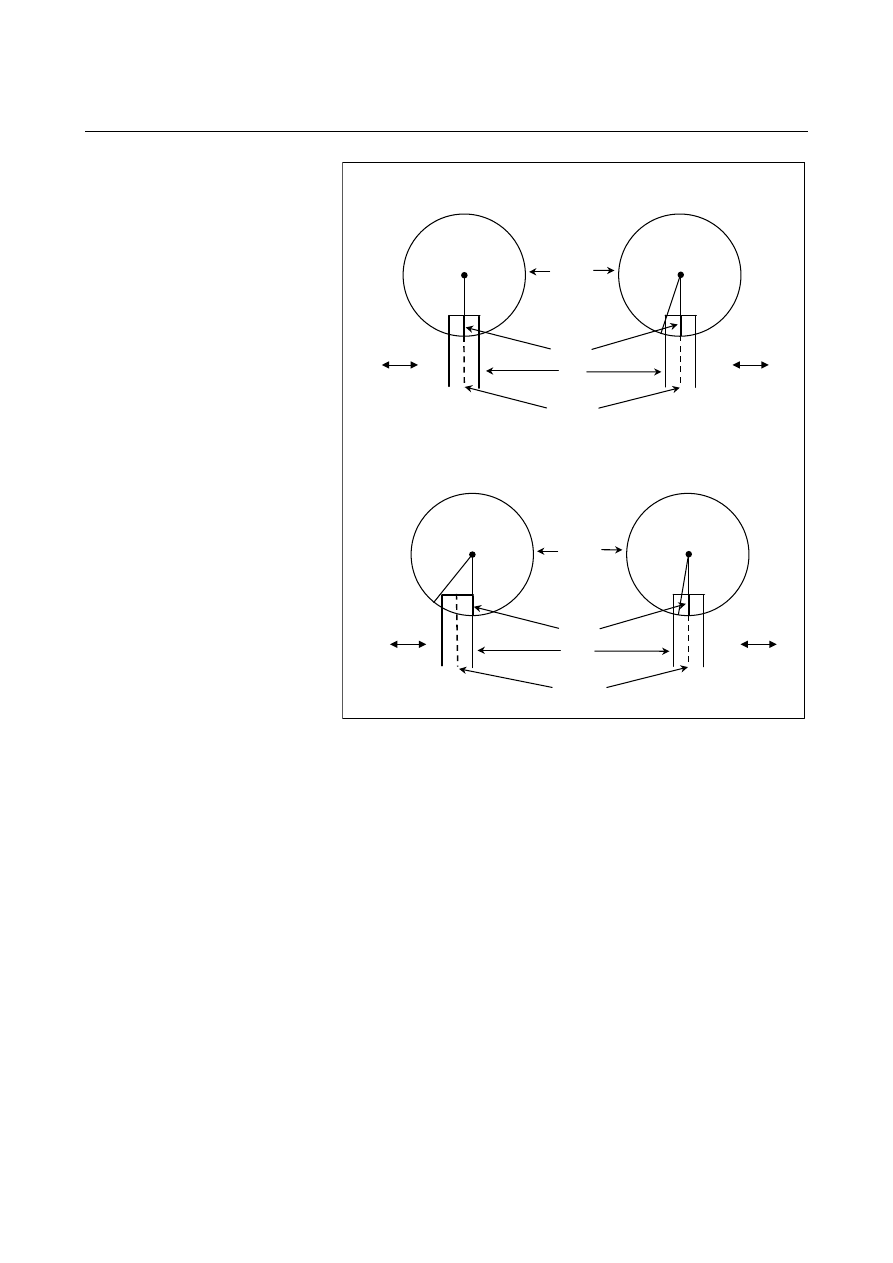
Fig. 4.10 (o)    Positional relationships between workpiece and tool of 

sample program 

 
The cutting surface in the rotary axis direction in (3) and (4) are 
uniform even if the tool radius compensation amount is modified. 
 

B-63944EN/03

 PROGRAMMING 

4.INTERPOLATION FUNCTIONS


- 101 - 

  - Example of specifying cutting point interpolation for cylindrical interpolation and 

normal direction control at the same time 

Tool radius compensation No.01 is 30 mm. 
O0002 (CYLINDRICAL INTERPOLATION2) ; 
N01 G00 G90 X100.0 A0 ; 
N02 G01 G91 G17 X0 A0 ; 
N03 G07.1 C57299 ; 
N04 G01 G41 G42.1 G90 X120.0 D01 F250. ; 
N05 A20.0 ; 
N06 G03 X80.0 A60.0 R40.0 ; 
N07 G01 X70.0 ; 
N08 G02 X70.0 A70.0 R10.0 ; 
N09 G01 A150.0 ; 
N10 G02 X70.0 A190.0 R85.0 ; 
N11 G01 X110.0 A265.0 ; 
N12 G03 X120.0 A305.0 R85.0 ; 
N13 G01 A360.0 ; 
N14 G40 G40.1 X100.0 ; 
N15 G07.1 A0 ; 
N16 M30 ; 

Z axis

A axis

Y axis
X axis

C axis


Fig. 4.10 (p)    Example of specifying normal direction control at the 

same time 


4.INTERPOLATION FUNCTIONS

 PROGRAMMING 

B-63944EN/03


- 102 - 

4.11 

EXPONENTIAL INTERPOLATION (G02.3, G03.3) 

 
Exponential interpolation exponentially changes the rotation of a 
workpiece with respect to movement on the rotary axis.    Furthermore, 
exponential interpolation performs linear interpolation with respect to 
another axis. This enables tapered groove machining with a constant 
helix angle (constant helix taper machining). This function is best 
suited for grooving and grinding tools such as taper end mills. 
 

Helix angle   

β

1

 = 

β

2

 = 

β

3

Z

A

X

β

1

β

3

β

2

A

(Rotary axis)

X (Linear axis)

X

A

Relationship between X-axis and A-axis


Fig. 4.11 (a)    Exponential interpolation 


B-63944EN/03

 PROGRAMMING 

4.INTERPOLATION FUNCTIONS


- 103 - 

Format 

Positive rotation (

ω

 = 0) 

  G02. 3    X_ Y_ Z_ I_ J_ K_ R_ F_ Q_ ; 
Negative rotation (

ω

 = 1) 

  G03. 3    X_ Y_ Z_ I_ J_ K_ R_ F_ Q_ ; 

X_  : Specifies an end point with an absolute or incremental value.
Y_  : Specifies an end point with an absolute or incremental value.
Z_  : Specifies an end point with an absolute or incremental value.
I_  : Specifies angle I (from 

±

1 to 

±

89 deg in units of 0.001 deg). 

J_  : Specifies angle J (from 

±

1 to 

±

89 deg in units of 0.001 deg). 

K_  : Specifies the amount to divide the linear axis for exponential 

interpolation (span value). The specification unit depends on 
the reference axis. Specify a positive value.   


  The span value is specified in the manner specified in bit 0 

(SPN) of parameter No. 5630. If SPN is set to 0, the division 
amount is specified in parameter No. 5643. If SPN is set to 
1, the value specified with K becomes valid. 

R_  : Specifies constant R for exponential interpolation. (See 

Explanations below.) 

F_  : Specifies the initial feedrate. 
 

  Specified in the same way as an ordinary F code. Specify a 

composite feedrate including a feedrate on the rotary axis. 

Q_  : Specifies the feedrate at the end point. 
 

  The same unit used for F is used. The CNC internally 

performs interpolation between the initial feedrate (F) and 
final feedrate (Q), depending on the travel distance on the 
linear axis. 


Explanation 


Z

A

X

I

B

r

J

U

X

Z(0)

r  :    Diameter of left end 
U :    Excess  length 
X :    Amount of travel along the linear axis 
I :  Taper angle 
B :    Groove bottom taper angle 
J :    Helix angle


Fig. 4.11 (b)    Constant helix machining for producing a tapered figure 

4.INTERPOLATION FUNCTIONS

 PROGRAMMING 

B-63944EN/03


- 104 - 

In Fig. 4.11 (b) an absolute value on the X-axis, Z-axis, or A-axis is 
expressed as a function of workpiece rotation angle 

θ

, such as 

X

(

θ

), 

Z

(

θ

), and 

A

(

θ

). 

Linear interpolation with the X-axis is performed for an axis other 
than the X-axis or A-axis. When 

X

(

θ

) = 0, 

A

(

θ

) = 0. 

 
The relationship is expressed as follows. 

{

}

(0)

)

tan(

)

tan(

*

1)

(

*

)

tan(

*

2

)

(

Z

I

B

e

I

U

r

θ

Z

K

θ

+

=

................. (1) 

{

}

)

tan(

1

*

1)

(

*

)

tan(

*

2

)

(

I

e

I

U

r

θ

X

K

θ

=

........................... (2) 

θ

π

θ

A

ω

*

2

360

*

1)

(

)

(

=


Where 

I

J

K

tan

tan

=


ω

:    Helix direction (0: Positive, 1: Negative) 

 
From Expressions (1) and    (2), the following is obtained ; 

(0)

)

(

*

)

tan(

)

(

Z

θ

X

B

θ

Z

+

=

.................................................. (3) 

From Expression (3), the Z-axis position is determined from a groove 
bottom taper angle (B) and X-axis position. 
From Expression (1) and exponential definition expression (described 
later), the following is determined: 

)

tan(

*

/2

I

U

r

R

=

.............................................................. (4) 

Constant R is determined from the left end diameter (r), excess length 
(U), and taper angle (I) according to Expression (4). Specify a taper 
angle (I) in address I, and specify a helix angle (J) in address J.  
Select a helix direction with G02.3 or G03.3. 
 

  - Exponential definition expressions 

Exponential relational expressions for a linear axis and rotary axis are 
defined as follows: 

)

tan(

1

*

1)

(

*

)

(

I

e

R

θ

X

K

θ

=

.................................................. (5) 

π

θ

θ

A

ω

2

*

360

*

1)

(

)

(

=

........................................................ (6) 

Where, 

)

tan(

)

tan(

I

J

K

=


0/1

=

ω


R, I, and J are constants, and 

θ

 represents an angle (radian). 


B-63944EN/03

 PROGRAMMING 

4.INTERPOLATION FUNCTIONS


- 105 - 

  - Span value K 

A movement on an axis is carried out as linear interpolation in units of 
values obtained by dividing the movement on the X-axis by the span 
value (address K). 
The following is obtained from Expression (5) 

1)

)

tan(

*

ln(

*

)

(

+

=

R

I

X

K

X

θ

................................................ (7) 

When there is movement from X

1

 to X

2

 on the linear axis, the amount 

of movement on the rotary axis is determined by: 

1)}

)

tan(

*

ln(

1)

)

tan(

*

{ln(

*

1

2

+

+

=

R

I

X

R

I

X

K

θ


X (linear axis)

Rotation angle 

θ

∆θ

K

X

2

X

1


Fig. 4.11 (c)    Span value K 


4.INTERPOLATION FUNCTIONS

 PROGRAMMING 

B-63944EN/03


- 106 - 

 - Rotation axis 

θ


In exponential interpolation, Expression (7) indicates the relationship 
between the X coordinate and the rotation angle 

θ

 about the A-axis.   

The expression in the parentheses of the natural logarithm ln in 
Expression (7) must satisfy Expression (8) indicated below, because 
of the condition of ln (the value in the parentheses is positive). 

1

)

tan(

*

>

R

I

X

................................................................... (8) 

If the value of X*tan(I)/R becomes -1 or less, the position comes to 
the right of point (A) in Fig. 4.11 (d). Because the resultant figure is 
unfeasible, an alarm PS5062 will be issued. 
 
In exponential interpolation, the X, Y, Z, and U values are handled as 
coordinates in the workpiece coordinate system. If a positive value 
specified in incremental programming corresponds to a negative value 
in the workpiece coordinate system, the negative value is used in the 
calculation. 
 

X

x

U

x*tan(I)

I

r

R

Origin of
workpiece
coordinate
system

x*tan(I)/R 

 -1

(A)

x*tan(I)/R > -1


Fig. 4.11 (d)    Rotation angle 

θ


B-63944EN/03

 PROGRAMMING 

4.INTERPOLATION FUNCTIONS


- 107 - 

  - Taper angle I 

The machining profile and the sign of taper angle I have the following 
relationships: 

  If the profile tapers up toward the right, the I value is positive. 

  If the profile tapers down toward the right, the I value is negative. 


X

Y

I > 0

I > 0

I < 0

I < 0

Y

Y

Y

X

X

X

Example)


Fig. 4.11 (e)    Taper angle I 


  - Helix angle J 

The sign of the helix angle J is assigned as illustrated below. 
 

X

J > 0

J > 0

X

Example)

X

J < 0

J < 0

X

J

J

J

J


Fig. 4.11 (f)    Helix angle J 


Content      ..     16      17      18      19     ..