FANUC Series 30i/300i/300is-MODEL A. Machining Center System. User's manual - page 14
4.INTERPOLATION FUNCTIONS
PROGRAMMING
B-63944EN/03
- 68 -
4.7
SPIRAL INTERPOLATION, CONICAL INTERPOLATION
(G02, G03)
Spiral interpolation is enabled by specifying the circular interpolation
command together with a desired number of revolutions or a desired
increment (decrement) for the radius per revolution.
Conical interpolation is enabled by specifying the spiral interpolation
command together with an additional axis of movement, as well as a
desired increment (decrement) for the position along the additional
axes per spiral revolution.
Format
- Spiral interpolation
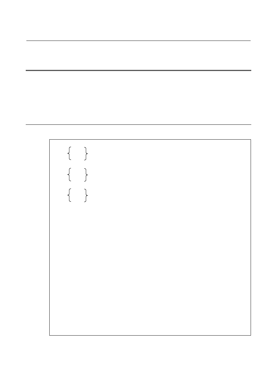
XpYp plane
G02
G17
G03
X_Y_I_J_Q_L_F_;
ZpXp plane
G02
G18
G03
Z_X_K_I_Q_L_F_;
YpZp plane
G02
G19
G03
Y_Z_J_K_Q_L_F_;
X, Y, Z : Coordinates of the end point
L
: Number of revolutions (positive value without a decimal point) (*1)
Q
: Radius increment or decrement per spiral revolution (*1, *2)
I, J, K : Signed distance from the start point to the center (same as the distance
specified for circular interpolation)
F :
Feedrate
(*1) Either the number of revolutions (L) or the radius increment or decrement (Q)
can be omitted. When L is omitted, the number of revolutions is automatically
calculated from the distance between the current position and the center, the
position of the end point, and the radius increment or decrement. When Q is
omitted, the radius increment or decrement is automatically calculated from the
distance between the current position and the center, the position of the end
point, and the number of revolutions. If both L and Q are specified but their
values contradict, Q takes precedence. Generally, either L or Q should be
specified. The L value must be a positive value without a decimal point. To
specify four revolutions plus 90°, for example, round the number of revolutions
up to five and specify L5.
(*2) The increment system for Q depends on the reference axis.