FANUC Robot M-710iC MECHANICAL UNIT. OPERATOR'S MANUAL (B-82274EN/09) - page 5
8.MASTERING
B-82274EN/09
(2) BLAL alarm
This alarm is output if the voltage of the Pulsecoder's backup battery has fallen to a level where
backup is no longer possible. If this alarm is output, fit a new battery immediately while
keeping the power turned on. Check whether the current position data is valid, using the
procedure described in 1.
(3) CKAL, RCAL, PHAL, CSAL, DTERR, CRCERR, STBERR, and SPHAL, alarms
Contact the FANUC because the Pulsecoder may be defective.
- 102 -

B-82274EN/09
9.TROUBLESHOOTING
9 TROUBLESHOOTING
9.1
OVERVIEW
The cause of a failure in the mechanical unit may be difficult to localize, because failures can arise from
many interrelated factors. If you fail to take the correct measures, the failure may be aggravated.
Therefore, it is necessary to analyze the symptoms of the failure precisely so that the true cause can be
found.
9.2
FAILURES, CAUSES AND MEASURES
Table 9.2 lists the major failures that may occur in the mechanical unit and their probable causes. If you
cannot pinpoint a failure cause or which measures to apply, contact FANUC.
Table 9.2 Failures, causes and measures
Symptom
Description
Cause
Measure
Vibration
-The J1 base lifts off the floor
[J1 base fastening]
-If a bolt is loose, apply
noise
plate as the robot operates.
-It is likely that the robot J1 base is not
LOCTITE and tighten it to the
-There is a gap between the J1
securely fastened to the base plate.
appropriate torque.
base and floor plate.
-Probable causes are a loose bolt, an
-Adjust the base plate surface
-A J1 base-retaining bolt is
insufficient degree of surface flatness,
flatness to within the specified
loose.
or foreign material caught between the
tolerance.
base plate and floor plate.
-If there is any foreign material
-If the robot is not securely fastened to
between the J1 base and base
the base plate, the J1 base lifts the
plate, remove it.
base plate as the robot operates,
-As the robot operates, the
allowing the base and floor plates to
rack or floor on which the robot
strike each other, which, in turn, leads
is mounted vibrates.
to vibration.
-Apply epoxy to the floor
[Rack or floor]
-Reinforce the rack or floor to
surface and re-install the plate.
-It is likely that the rack or floor is not
make it more rigid.
sufficiently rigid.
-If it is impossible to reinforce
-If the rack or floor is not sufficiently
the rack or floor, modify the
rigid, reaction from the robot deforms
robot control program; doing
the rack or floor, leading to vibration.
so might reduce the amount of
vibration.
-Vibration becomes more
[Overload]
-Check the maximum load that
serious when the robot adopts
-It is likely that the load on the robot is
the robot can handle once
a specific posture.
greater than the maximum rating.
more. If the robot is found to
-If the operating speed of the
-It is likely that the robot control
be overloaded, reduce the
robot is reduced, vibration
program is too demanding for the
load, or modify the robot
stops.
robot hardware.
control program.
-Vibration is most noticeable
-It is likely that the ACCELERATION
-Vibration in a specific portion
when the robot is accelerating.
value is excessive.
can be reduced by modifying
-Vibration occurs when two or
the robot control program while
more axes operate at the same
slowing the robot and reducing
time.
its acceleration (to minimize
the influence on the entire
cycle time).
- 103 -

9.TROUBLESHOOTING
B-82274EN/09
Symptom
Description
Cause
Measure
Vibration
-Vibration or noise was first
[Broken gear, bearing, or reducer]
-Operate one axis at a time to
Noise
noticed after the robot collided
- It is likely that collision or overload
determine which axis is
(Continued)
with an object or the robot was
applied an excessive force on the
vibrating.
overloaded for a long period.
drive mechanism, thus damaging the
-Remove the motor, and
-The grease of the vibrating or
geartooth surface or rolling surface of
replace the gear , the bearing,
noise occurring axis has not
a bearing, or reducer.
and the reducer. For the spec.
been exchanged for a long
- It is likely that prolonged use of the
of parts and the method of
period.
robot while overloaded caused fretting
replacement, contact FANUC.
-There is vibration or unusual
of the gear tooth surface or rolling
-Using the robot within its
sound just after replacing
surface of a bearing, or reducer due to
maximum rating prevents
grease or oil or parts.
resulting metal fatigue.
problems with the drive
- It is likely that foreign material
mechanism.
caught in a gear, bearing, or within a
-Regularly changing the grease
reducer caused damage on the gear
with a specified type can help
tooth surface or rolling surface of the
prevent problems.
bearing, or reducer.
- It is likely that foreign material
caught in a gear, bearing, or within a
reducer cause vibration.
- It is likely that, because the grease
has not been changed for a long
period, fretting occurred on the gear
tooth surface or rolling surface of a
bearing, or reducer due to metal
fatigue.
These factors all generate cyclic
vibration and noise.
- 104 -

B-82274EN/09
9.TROUBLESHOOTING
Symptom
Description
Cause
Measure
Vibration
-The cause of problem cannot
[Controller, cable, and motor]
-Refer to the Controller
Noise
be identified from examination
-If a failure occurs in a controller
Maintenance Manual for
(Continued)
of the floor, rack, or
circuit, preventing control commands
troubleshooting related to the
mechanical section.
from being supplied to the motor
controller and amplifier.
normally, or preventing motor
-Replace the Pulsecoder for
information from being sent to the
the motor of the axis that is
controller normally, vibration might
vibrating, and check whether
occur.
the vibration still occurs.
-If the Pulsecoder develops a fault,
-Also, replace the motor of the
vibration might occur because
axis that is vibrating, and
information about the motor position
check whether vibration still
cannot be transferred to the controller
occurs. For the method of
accurately.
replacement, contact FANUC.
-If the motor becomes defective,
-Check that the robot is
vibration might occur because the
supplied with the rated voltage.
motor cannot deliver its rated
-Check whether the sheath of
performance.
the power cord is damaged. If
-If a power line in a movable cable of
so, replace the power cord,
the mechanical section has an
and check whether vibration
intermittent break, vibration might
still occurs.
occur because the motor cannot
-Check whether the sheath of
accurately respond to commands.
the cable connecting the
-If a Pulsecoder wire in a movable part
mechanical section and
of the mechanical section has an
controller is damaged. If so,
intermittent break, vibration might
replace the connection cable,
occur because commands cannot be
and check whether vibration
sent to the motor accurately.
still occurs.
-If a connection cable between them
-If vibration occurs only when
has an intermittent break, vibration
the robot assumes a specific
might occur.
posture, it is likely that a cable
-If the power supply cable is about to
in the mechanical unit is
be snapped, vibration might occur.
broken.
-If the power source voltage drops
-Shake the movable part cable
below the rating, vibration might
while the robot is at rest, and
occur.
check whether an alarm
-If a robot control parameter is set to
occurs. If an alarm or any other
an invalid value, vibration might occur.
abnormal condition occurs,
replace the mechanical unit
cable.
-Check that the robot control
parameter is set to a valid
value. If it is set to an invalid
value, correct it. Contact
FANUC for further information
if necessary.
- 105 -

9.TROUBLESHOOTING
B-82274EN/09
Symptom
Description
Cause
Measure
Vibration
-There is some relationship
[Noise from a nearby machine]
-Connect the grounding wire
Noise
between the vibration of the
-If the robot is not grounded properly,
firmly to ensure a reliable
(Continued)
robot and the operation of a
electrical noise is induced on the
ground potential and prevent
machine near the robot.
grounding wire, preventing commands
extraneous electrical noise.
from being transferred accurately,
thus leading to vibration.
-If the robot is grounded at an
unsuitable point, its grounding
potential becomes unstable, and
noise is likely to be induced on the
grounding line, thus leading to
vibration.
- There is an unusual sound
- There may be an unusual sound
- Use the specified grease.
after replacement of grease.
when using other than the specified
- When there is an unusual
- There is an unusual sound
grease.
sound even for specified
after a long period.
- Even for the specified grease, there
grease, perform operation
- There is an unusual sound
may be an unusual sound during
for one or two days on an
during operation at low
operation at low speed immediately
experiment. Generally, a
speed.
after replacement or after a long
usual sound will disappear.
period.
Rattling
-While the robot is not supplied
[Mechanical section coupling bolt]
-Check that the following bolts
with power, pushing it with the
-It is likely that overloading or a
for each axis are tight. If any of
hand causes part of the
collision has loosened a mounting bolt
these bolts is loose, apply
mechanical unit to wobble.
in the robot mechanical section.
LOCTITE and tighten it to the
-There is a gap on the
appropriate torque.
mounting surface of the
-Motor retaining bolt
mechanical unit.
-Reducer retaining bolt
-Reducer shaft retaining bolt
-Base retaining bolt
-Arm retaining bolt
-Casting retaining bolt
-End effecter retaining bolt
- 106 -

B-82274EN/09
9.TROUBLESHOOTING
Symptom
Description
Cause
Measure
Motor
-The ambient temperature of
[Ambient temperature]
The teach pendant can be
overheating
the installation location
-It is likely that a rise in the ambient
used to monitor the average
increases, causing
temperature or attaching the motor
current. Check the average
the motor to overheat.
cover prevented the motor from
current when the robot control
-After a cover was attached to
releasing heat efficiently, thus leading
program is running. The
the motor, the motor
to overheating.
allowable average current is
overheated.
[Operating condition]
specified for the robot
-After the robot control
-It is likely that the robot was operated
according to its ambient
program or the load was
with the maximum average current
temperature. Contact FANUC
changed, the motor
exceeded.
for further information.
overheated.
-Relaxing the robot control
program and conditions can
reduce the average current,
thus preventing overheating.
-Reducing the ambient
temperature is the most
effective means of preventing
overheating.
-Having the surroundings of
the motor well ventilated
enables the motor to release
heat efficiently, thus preventing
overheating. Using a fan to
direct air at the motor is also
effective.
-If there is a source of heat
near the motor, it is advisable
to install shielding to protect
the motor from heat radiation.
-After a control parameter was
[Parameter]
-Input an appropriate
changed, the motor
-If data input for a workpiece is invalid,
parameter as described in
overheated.
the robot cannot be accelerated or
CONTROLLER OPERATOR’S
decelerated normally, so the average
MANUAL.
current increases, leading to
overheating.
-Symptom other than stated
[Mechanical section problems]
Repair the mechanical unit
above
-It is likely that problems occurred in
while referring to the above
the mechanical unit drive mechanism,
descriptions of vibration, noise,
thus placing an excessive load on the
and rattling.
motor.
-Check that, when the servo
[Motor problems]
system is energized, the brake
-It is likely that a failure of the motor
is released.
brake resulted in the motor running
-If the brake remains applied to
with the brake applied, thus placing an
the motor all the time, replace
excessive load on the motor.
the motor.
-It is likely that a failure of the motor
-If the average current falls
prevented it from delivering its rated
after the motor is replaced, it
performance, thus causing an
indicates that the first motor
excessive current to flow through the
was faulty.
motor.
- 107 -

9.TROUBLESHOOTING
B-82274EN/09
Symptom
Description
Cause
Measure
Grease
-Grease is leaking from the
[Poor sealing]
-If a crack develops in the
leakage
mechanical unit.
-Probable causes are a crack in the
casting, sealant can be used
casting, a broken O-ring, a damaged
as a quick-fix to prevent further
oil seal, or a loose seal bolt.
grease leakage. However, the
-A crack in a casting can occur due to
component should be replaced
excessive force that might be caused
as soon as possible, because
in collision.
the crack might extend.
-An O-ring can be damaged if it is
-O-rings are used in the
trapped or cut during disassembling or
locations listed below.
re-assembling.
-Motor coupling section
-An oil seal might be damaged if
-Reducer (case and shaft)
extraneous dust scratches the lip of
coupling section
the oil seal.
-Wrist coupling section
-A loose seal bolt might allow grease
-J3 arm coupling section
to leak along the threads.
-Inside the wrist
-Problems with the grease nipple or
-Oil seals are used in the
threads.
locations stated below.
-Inside the reducer
-Inside the wrist
-Seal bolts are used in the
locations stated below.
-Grease drain outlet
-Replace the grease nipple.
Dropping
-An axis drops because the
[Brake drive relay and motor]
-Check whether the brake drive
axis
brake does not function.
-It is likely that brake drive relay
relay contacts are stuck to
-An axis drops gradually when
contacts are stuck to each other to
each other. If they are found to
it should be at rest.
keep the brake current flowing, thus
be stuck, replace the relay.
preventing the brake from operating
-If the brake shoe is worn out,
when the motor is deenergized.
if the brake main body is
-It is likely that the brake shoe has
damaged, or if oil or grease
worn out or the brake main body is
has entered the motor, replace
damaged, preventing the brake from
the motor.
operating efficiently.
-It is likely that oil or grease has
entered the motor, causing the
brake to slip.
- 108 -

B-82274EN/09
9.TROUBLESHOOTING
Symptom
Description
Cause
Measure
Displace-
-The robot operates at a point
[Mechanical section problems]
-If the repeatability is unstable,
ment
other than the taught position.
-If the repeatability is unstable,
repair the mechanical section
-The repeatability is not within
probable causes are a failure in the
by referring to the above
the tolerance.
drive mechanism or a loose bolt.
descriptions of vibration, noise,
-If the repeatability becomes stable, it
and rattling.
is likely that a collision imposed an
-If the repeatability is stable,
excessive load, leading to slipping on
correct the taught program.
the base surface or the mating
Variation will not occur unless
surface of an arm or reducer.
another collision occurs.
-It is likely that the Pulsecoder is
-If the Pulsecoder is abnormal,
abnormal.
replace the motor or the
Pulsecoder.
-Displacement occurs only in a
[Peripheral unit displacement]
-Correct the setting of the
specific peripheral unit.
-It is likely that an external force was
peripheral unit position.
applied to the peripheral unit, thus
-Correct the taught program.
shifting its position relative to the
robot.
-Displacement occurred after a
[Parameter]
-Re-enter the previous
parameter was changed.
-It is likely that the mastering data was
mastering data, which is known
rewritten in such a way that
to be correct.
the robot origin was shifted.
-If correct mastering data is
unavailable, perform mastering
again.
BZAL alarm
-BZAL is displayed on the
-It is likely that the voltage of the
-Replace the battery.
occurred
controller screen
memory backup battery is low.
-Replace the cable.
-It is likely that the Pulsecoder cable is
defected.
- 109 -
10.SEVERE DUST/LIQUID PROTECTION PACKAGE (OPTION)
B-82274EN/09
10 SEVERE DUST/LIQUID PROTECTION
PACKAGE (OPTION)
10.1 OVERVIEW
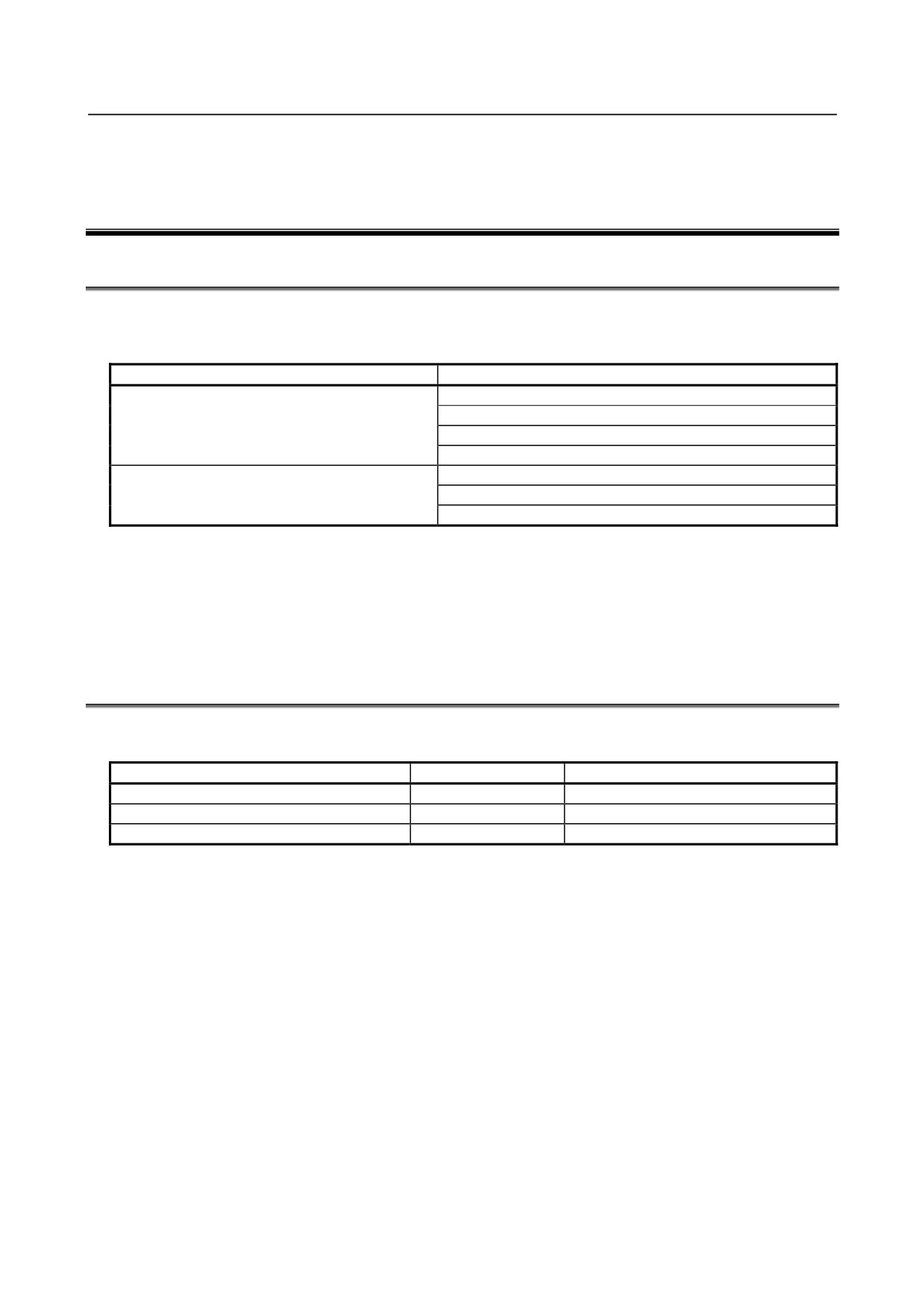
The package is intended to improve the Severe dust/liquid protection characteristics of the robot so that it
can be used in a severe environment.
Model
Severe dust/liquid protection specification
M-710iC/50, M-710iC/70
A05B-1125-J801 (*1)
A05B-1125-J811 (*2)
A05B-1125-J823 (*3)
A05B-1125-J829 (*4)
M-710iC/50S
A05B-1125-J802 (*1)
A05B-1125-J812 (*4)
A05B-1125-J824 (*5)
(*1) When mechanical unit cable for camera is not selected.
(*2) When mechanical unit cable for camera A05B-1125-H403 is selected.
(*3) When mechanical unit cable for camera A05B-1125-H404 is selected.
(*4) When mechanical unit cable for camera A05B-1125-H405 is selected.
(*5) When mechanical unit cable for camera A05B-1125-H421 is selected.
(*6) When mechanical unit cable for camera A05B-1125-H422 is selected.
10.2 SEVERE DUST/LIQUID PROTECTION CHARACTERISTICS
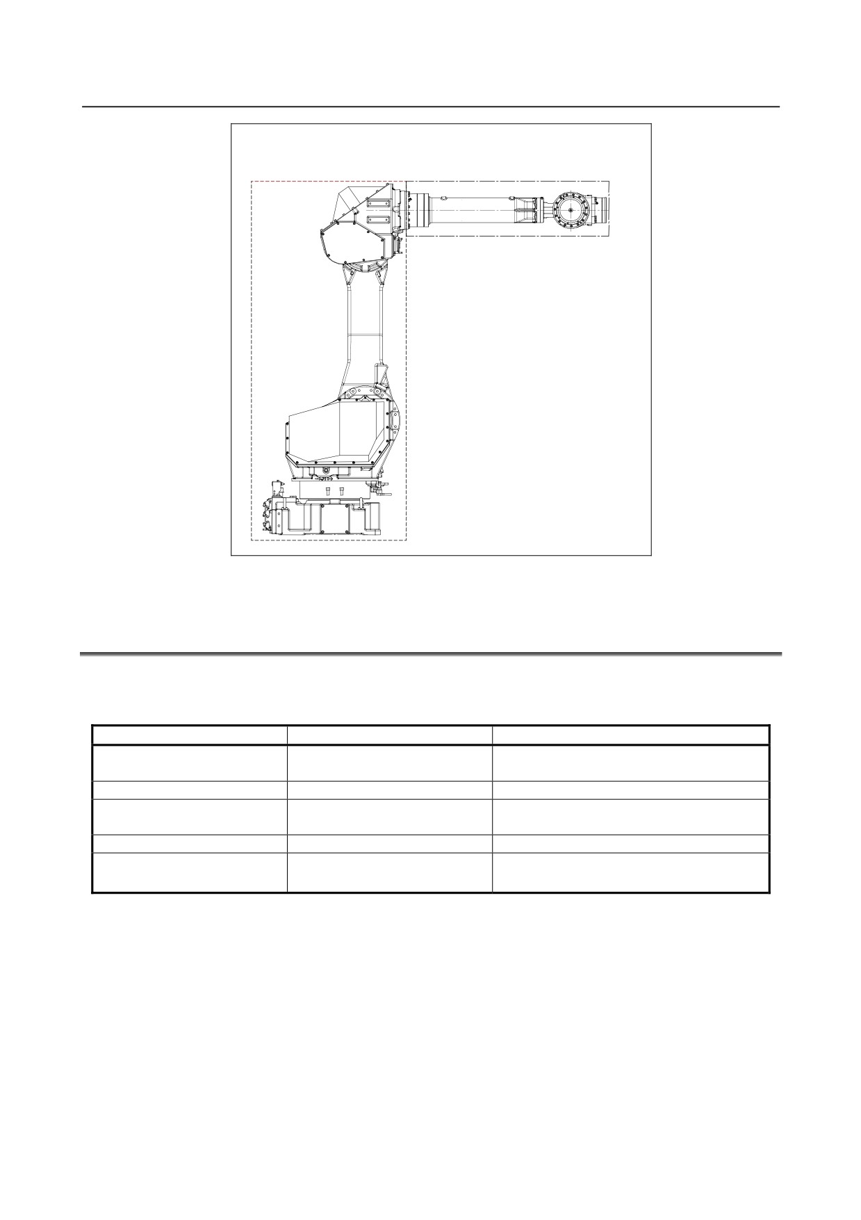
The following table lists the IEC529-based Severe dust/liquid protection characteristics of the M-710iC.
Standard
Severe dust/liquid protection package
J3 arm and wrist section
IP67
IP67
Drive unit of the main body
IP66
IP67
Main body
IP54
IP67
- 110 -
B-82274EN/09
10.SEVERE DUST/LIQUID PROTECTION PACKAGE (OPTION)
Main body
J3 arm + Wrist unit
Fig. 10.2 Severe dust/liquid protection characteristics of the M-710iC
10.3 CONFIGURATION OF THE SEVERE DUST/LIQUID
PROTECTION PACKAGE
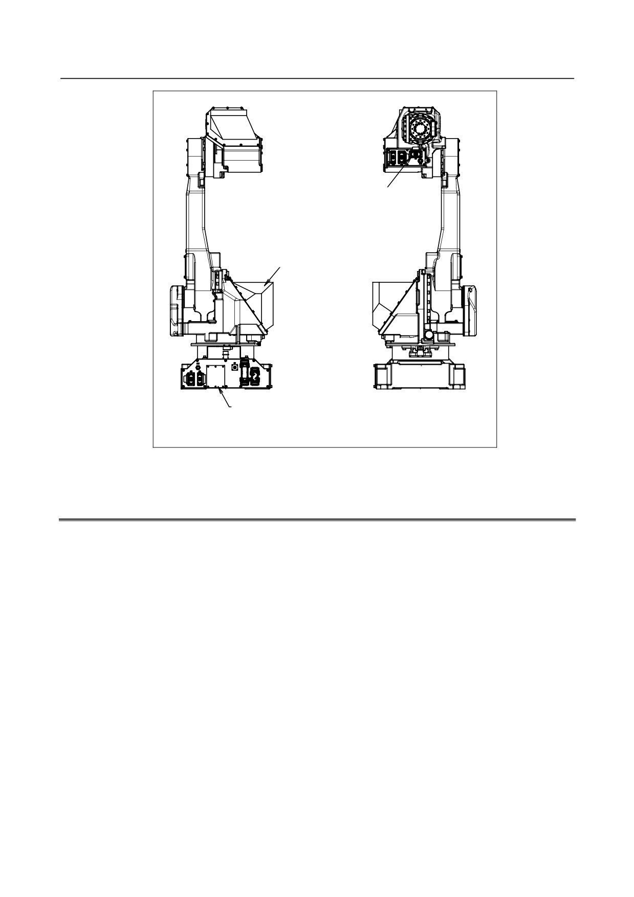
The following table lists the major differences between the M-710iC standard specification and Severe
dust/liquid protection package.
Standard specification
Severe dust/liquid protection option
Bolts
Dyed black steel bolt
FR coating bolt
Stainless bolt
Washer
Dyed black washer
Black chrome washer
Cover
J2 cover
Battery box cover
EE(RI/RO) connector
Non-waterproof connector
Waterproof connector
Others
Gasket
Packing is added.
- 111 -
10.SEVERE DUST/LIQUID PROTECTION PACKAGE (OPTION)
B-82274EN/09
EE (RI/RO) waterproof
connector
J2 cover
Battery box cover
Back
Front
Fig. 10.3 Configuration of the severe dust/liquid protection package of M-710iC
10.4 NOTES ON SPECIFYING SEVERE DUST/LIQUID
PROTECTION PACKAGE
1
The liquids below cannot be applied because they may cause deterioration or corrosion of the rubber
parts (such as packings, oil seals, and O-rings) used in the robot.
(a) Organic solvent
(b) Chlorine- or gasoline-based cutting fluid
(c) Amine-based cleaning fluid
(d) Liquid or solution that includes a corrosive such as an acid or alkali or causes rust
(e) Some other liquid or solution to which nitrile rubber (NBR) does not have resistance
2
When the robot is used in an environment where a liquid such as water is dashed over the robot,
great attention should be given to drainage under the J1 base.
A failure may be caused if the J1 base is kept immersed in water due to poor drainage.
3
This option can be used only when the J2 cover is selected.
4
Please be sure to exchange it for the new article when you remove the gasket or packings by the
component replacement and the check.
- 112 -
B-82274EN/09
11.CORRESPOND TO WASHING APPLICATION (OPTION)
11 CORRESPOND TO WASHING
APPLICATION (OPTION)
11.1 ABOUT CORRESPOND TO WASHING APPLICATION
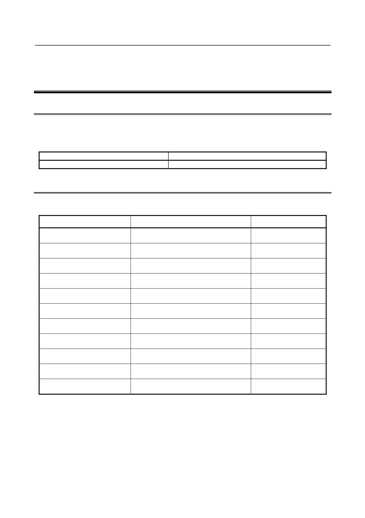
CORRESPOND TO WASHING APPLICATION is intended to improve the Severe dust/liquid protection
characteristics of the robot so that it can be used in a severe environment like wet scrubber.
This option includes Severe dust/liquid protection option.
Model
Severe dust/liquid protection specification
M-710iC/50, M-710iC/70
A05B-1125-J809
11.2 NOTES OF CORRESPOND TO WASHING APPLICATION
1
CORRESPOND TO WASHING APPLICATION specifies cleaning liquids usable with the robot.
(Always keep all the liquids at or below 60°C.)
Liquid model name
Manufacturer name
Permissible concentration
5.0%
CleanMate MS-1
TOHO Chemical Industry Co., LTD.
Diluted to 20 parts of water
2.0%
Toyosol ST-91P
Toyoda Chemical Industry Co., Ltd.
Diluted to 50 parts of water.
5.0%
Toyosol SE-78P
Toyoda Chemical Industry Co., Ltd.
Diluted to 20 parts of water.
3.0%
TOYOKNOCK RE-777P
Toyoda Chemical Industry Co., Ltd.
Diluted to 33 parts of water.
3.0%
MP-70
Henkel Japan
Diluted to 33 parts of water.
5.0%
Pakuna FD-800
YUKEN Industry CO., LTD.
Diluted to 20 parts of water.
3.3%
Yushiro cleaner W51H
YUSHIRO CHEMICAL INDUSTRY CO., LTD.
Diluted to 30 parts of water.
3.3%
Yushiro cleaner W80
YUSHIRO CHEMICAL INDUSTRY CO., LTD.
Diluted to 30 parts of water.
5.0%
SP-414
PLODUCTOCHEMIHALS
Diluted to 20 parts of water.
5.0%
SP-424
PLODUCTOCHEMIHALS
Diluted to 20 parts of water.
5.0%
SP-260
PLODUCTOCHEMIHALS
Diluted to 20 parts of water.
2
Note that applying a cleaning liquid not included in the specification or one beyond its permissible
concentration or temperature even if it is included in the specification to the robot may results in
serious damage to the robot.
3
The cables connecting the robot, controller, and external battery are not resistant to any cleaning
liquid. So, install them in such a way that no cleaning liquid will be splashed to the cables.
- 113 -
11.CORRESPOND TO WASHING APPLICATION (OPTION)
B-82274EN/09
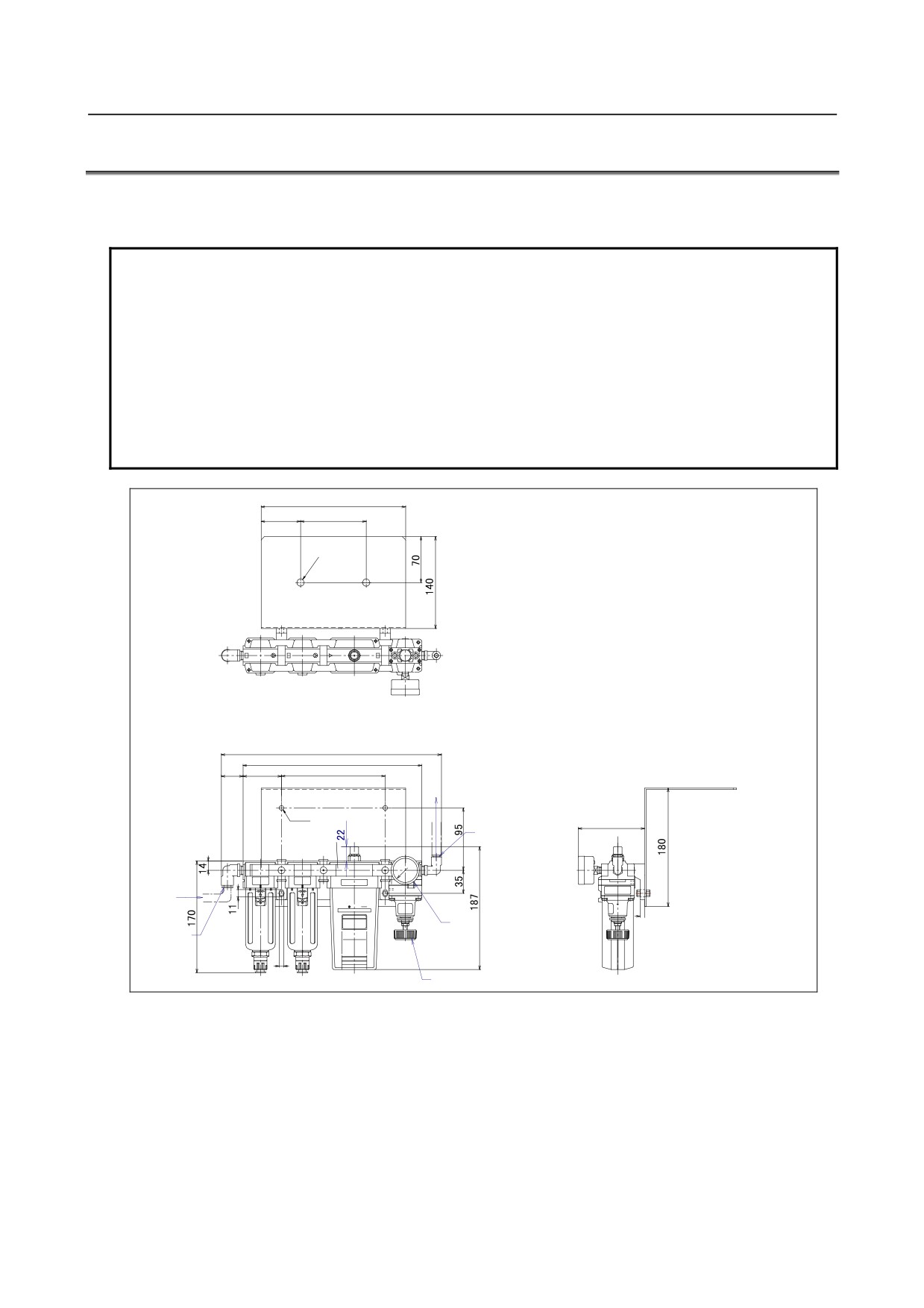
11.3 INSTALLING THE AIR PURGE KIT
Use the prepared air purge kit.
Set the air purge pressure to 10 kPa (0.1 kgf/cm2).
NOTE
1 It is recommended that a dedicated air pressure source be used for an air purge. Do not
use the same air pressure source for both the air purge kit and others. Otherwise, the
dryer capacity is exceeded and water or oil remains in air, causing serious damage to
the robot.
2 After installing the robot, perform an air purge at all times.
Even when the robot is not operating, an air purge is required if it is placed in a bad
condition.
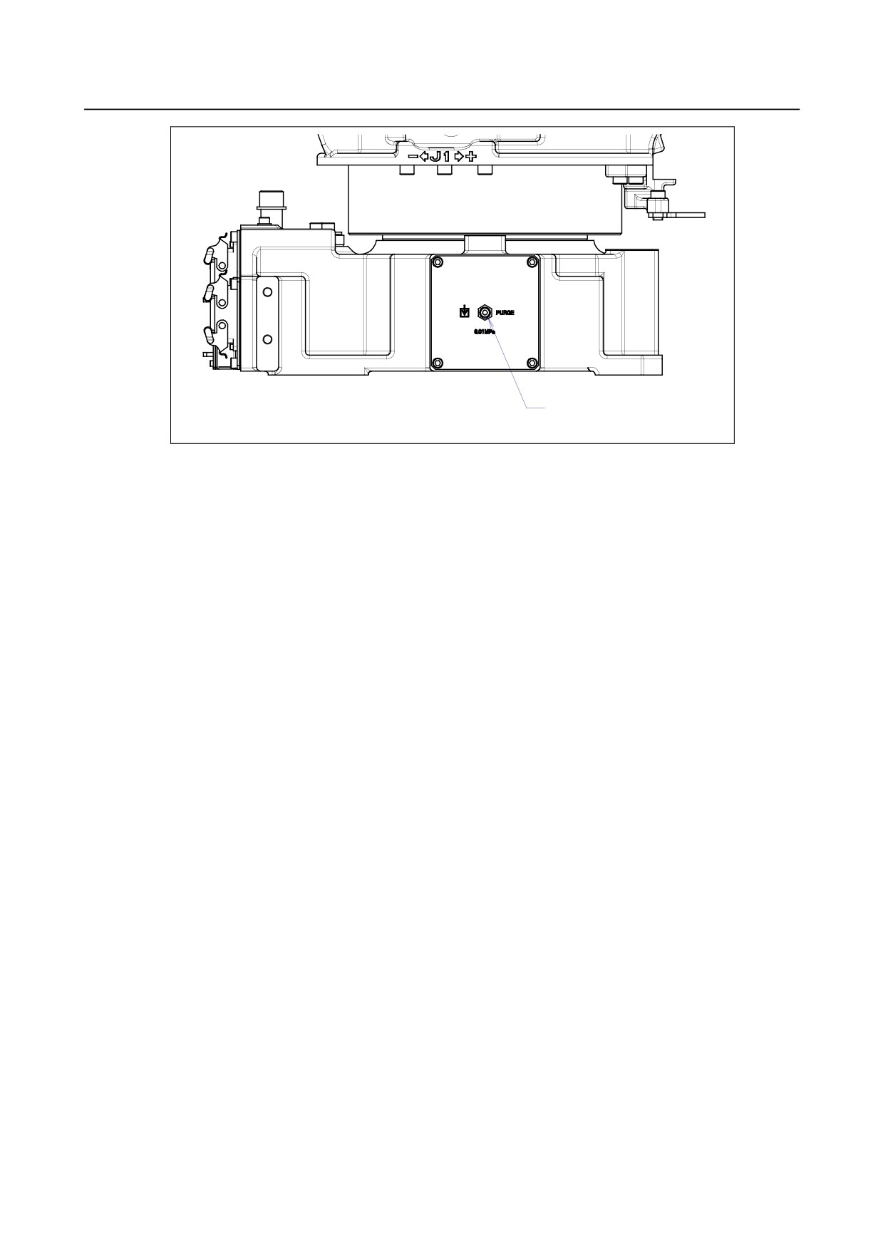
3 When removing the air tube from the air inlet of the J1 connector panel, replace the joint
together. Be careful to prevent cleaning fluids from entering into the joint. Otherwise,
rubbers in the joint are degraded and the robot may be damaged.
䎕䎕䎓
䎙䎓
䎔䎓䎓
䎕䎐䕎䎔䎔
䎋䎖䎖䎘䎌
䎕䎚䎕
䎋䎖䎖䎌
䎘䎜
䎔䎘䎛
㪧㪬㪩㪞㪜㩷㪺㫆㫅㫅㪼㪺㫋㫆㫉
㩿㪡㪈㩷㪺㫆㫅㫅㪼㪺㫋㫆㫉㩷㫇㪸㫅㪼㫃㪀
䎗䎐䕎䎚
䎋䎔䎓䎔䎌
㪘㫀㫉㩷㫆㫌㫋㫃㪼㫋
䎗䎔
㩿O㪍㩷㪘㫀㫉㩷㫋㫌㪹㪼㪀
㪧㫅㪼㫌㫄㪸㫋㫀㪺
㪸㫀㫉㩷㫆㫌㫋㫃㪼㫋
䎚
㪧㫉㪼㫊㫊㫌㫉㪼㩷㪾㪸㫌㪾㪼
㪘㫀㫉㩷㫀㫅㫃㪼㫋
㩿O㪈㪇㩷㪘㫀㫉㩷㫋㫌㪹㪼㪀
䎚
㪧㫉㪼㫊㫊㫌㫉㪼㩷㪸㪻㫁㫌㫊㫋㫄㪼㫅㫋㩷㫂㫅㫆㪹
Fig 11.3 (a) Air purge kit outside dimensions
- 114 -
B-82274EN/09
11.CORRESPOND TO WASHING APPLICATION (OPTION)
㪠㫅㫃㪼㫋㩷㫇㫆㫉㫋㩷㪽㫆㫉㩷㪸㫀㫉㩷㫇㫌㫉㪾㪼
O䇭㪍
Fig 11.3 (b) Mounting position of air purge to robot
- 115 -
12.MOTOR AIR BLOW OPPTION (OPTION)
B-82274EN/09
12 MOTOR AIR BLOW OPPTION (OPTION)
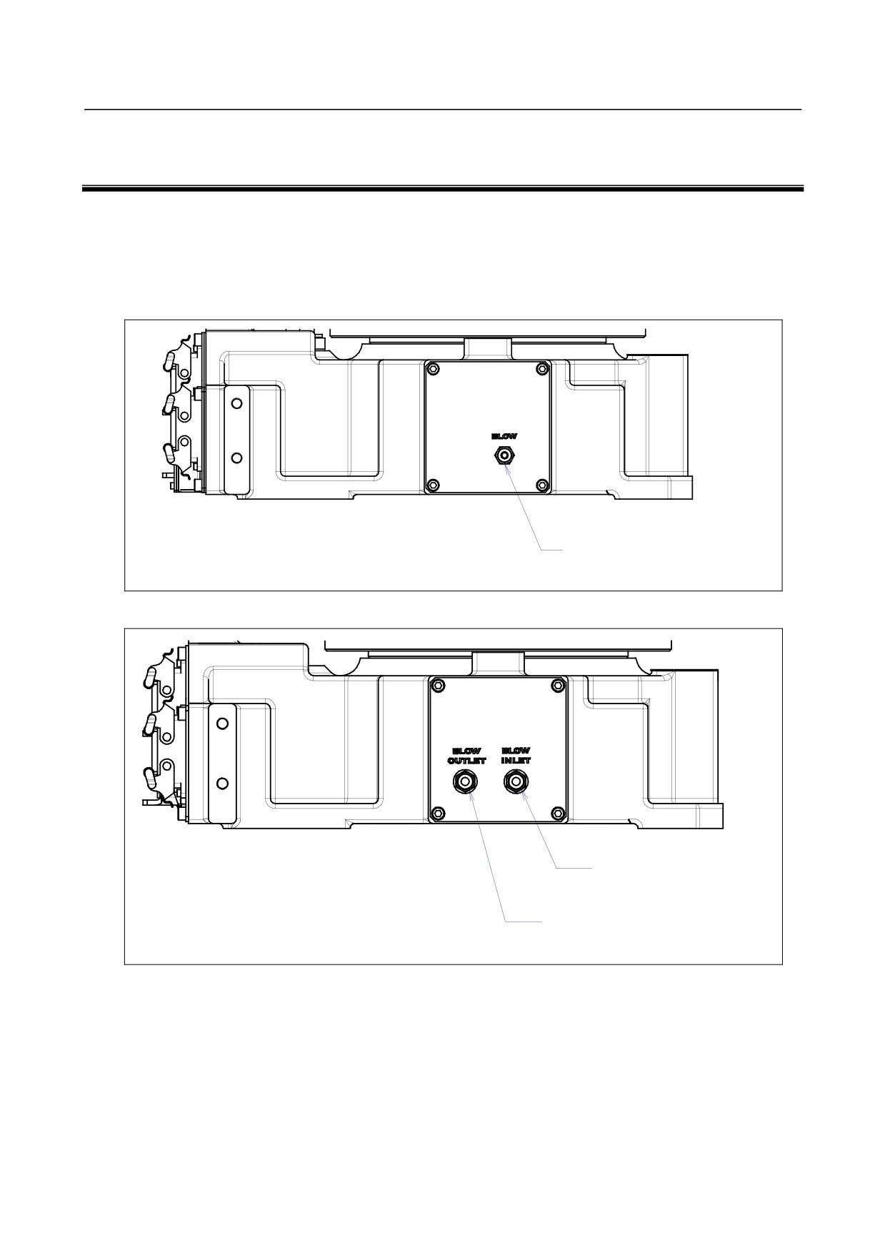
When motor air blow option is specified, inlet port is attached to the side of the J1 base.
When severe dust/liquid protection option is specified, exhaust port is attached ,too.
Supply air pressure is 0.49 to 0.69MPa(5 to 7kgf/cm2).
・ Use dry air.
・ Do not close the exhaust of J1 side when using both severe dust/liquid protection and air blow.
Inlet port for air blow
O 6
Fig.12(a) Inlet port for air blow
Inlet port for air blow
O 6
Outlet port for air blow
O 6
Fig.12(b) Inlet port and outlet port for air blow (When severe dust/liquid protection option is specified)
- 116 -
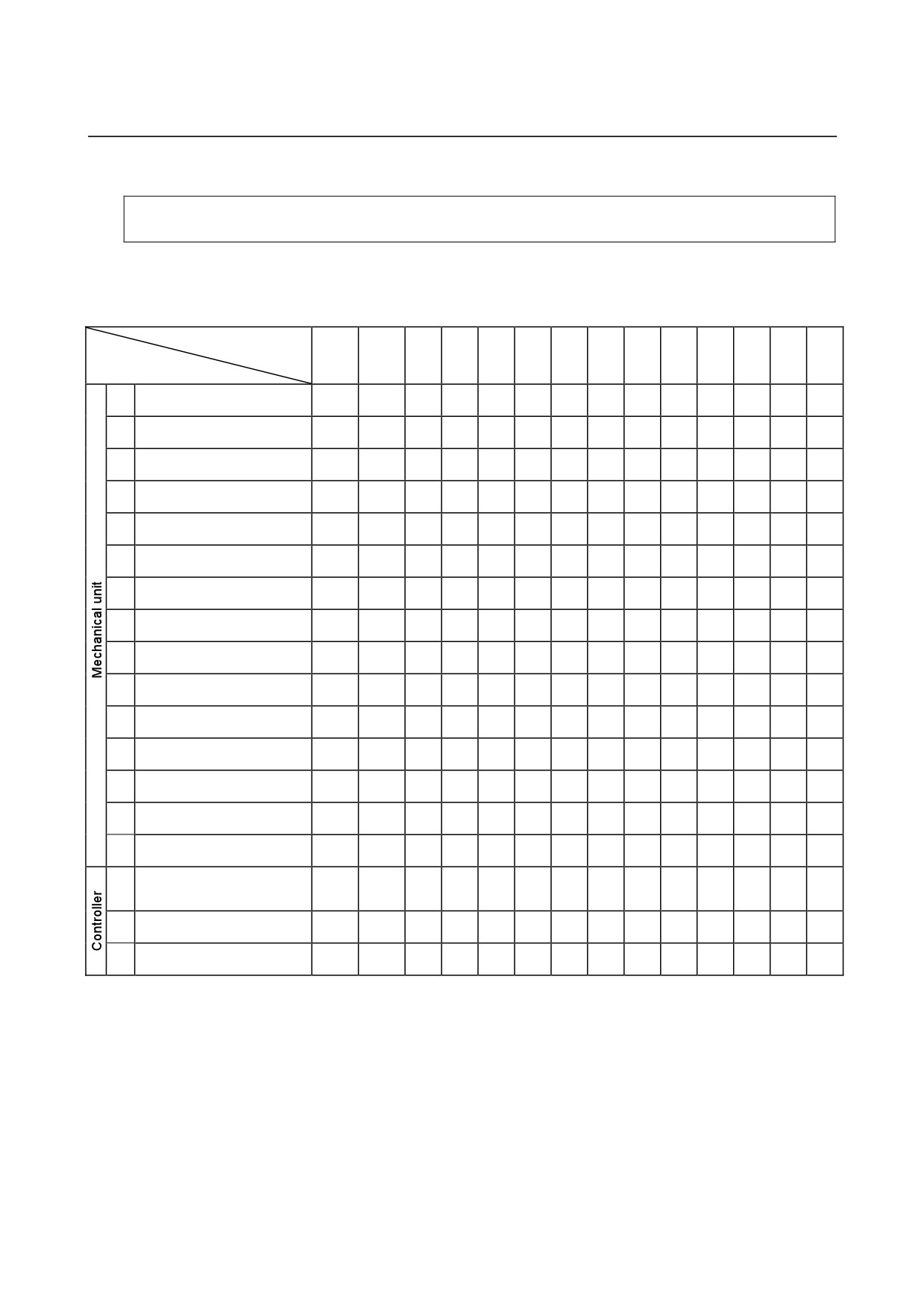
A.PERIODIC MAINTENANCE TABLE APPENDIX
B-82274EN/09
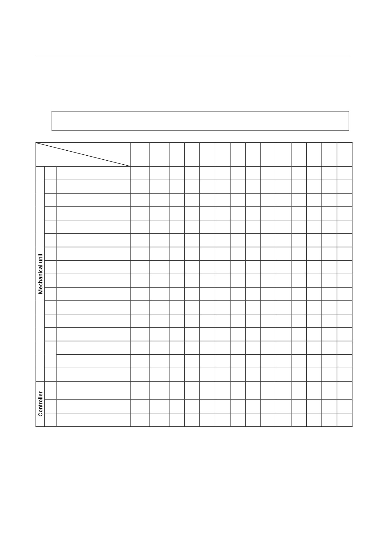
FANUC Robot M-710iC/50,70,50S,50E
Periodic Maintenance Table
First
Working time (H)
3
6
9
1
2
Check
Grease
check
months
months
months
year
years
time
amount
320
960
1920
2880
3840
4800
5760
6720
7680
8640
9600
10560
Items
Check the mechanical cable.
1
0.2H
-
○
○
(damaged or twisted)
Check the motor connector.
2
0.2H
-
○
○
(loosening)
3
Tighten the end effector bolt.
0.2H
-
○
○
○
Tighten the cover and main
4
2.0H
-
○
○
○
bolt.
5
Check the mechanical stopper
0.1H
○
○
○
6
Remove spatter and dust etc.
1.0H
-
○
○
○
Check the end effector (hand)
7
0.1H
-
○
○
○
cable
8
Check the fan
0.1H
-
○
○
○
9
Replacing battery.
0.1H
-
●
Replacing grease of J1 axis
10
0.5H
3300ml
reducer
Replacing grease of J2 axis
11
0.5H
1660ml
reducer
Replacing grease of J3 axis
12
0.5H
1060ml
reducer
Replacing grease of
13
0.5H
920ml
J4/J5/J6-axis gearbox
Replacing grease of wrist axis
0.5H
610ml
unit
(M-710iC/50, /70, /50S)
14
Replacing grease of wrist axis
0.5H
580ml
unit
(M-710iC/50E)
Replacing cable of mechanical
15
4.0H
-
unit
Check the robot cable, teach
16
pendant cable and robot
0.2H
-
○
○
○
connecting cable
17
Cleaning the ventilator
0.2H
-
○
○
○
○
○
○
○
○
○
○
○
○
18
Replacing battery *1
0.1H
-
*1 Refer to manual of controller.
*2
●: requires order of parts
○: requires order of parts
- 120 -

B-82274EN/09
APPENDIX A.PERIODIC MAINTENANCE TABLE
4
5
6
7
8
3
years
years
years
years
years
years
11520
12480
13440
14400
15360
16320
17280
18240
19200
20160
21120
22080
23040
24000
24960
25920
26880
27840
28800
29760
30720
Item
○
○
○
○
○
1
○
○
○
○
○
2
○
○
○
○
○
3
○
○
○
○
○
4
○
○
○
○
○
5
○
○
○
○
○
6
○
○
○
○
○
7
○
○
○
○
○
8
●
●
●
●
9
●
●
10
●
●
11
●
●
12
●
●
13
●
●
14
●
●
●
15
○
○
○
○
○
16
○
○
○
○
○
○
○
○
○
○
○
○
○
○
○
○
○
○
○
○
17
●
18
- 121 -
A.PERIODIC MAINTENANCE TABLE APPENDIX
B-82274EN/09
FANUC Robot M-710iC/50H
Periodic Maintenance Table
First
Working time (H)
3
6
9
1
2
Check
Grease
check
months
months
months
year
years
time
amount
320
Items
960
1920
2880
3840
4800
5760
6720
7680
8640
9600
10560
Check the mechanical cable.
1
0.2H
-
○
○
(damaged or twisted)
Check the motor connector.
2
0.2H
-
○
○
(loosening)
3
Tighten the end effector bolt.
0.2H
-
○
○
○
Tighten the cover and main
4
2.0H
-
○
○
○
bolt.
5
Check the mechanical stopper
0.1H
○
○
○
6
Remove spatter and dust etc.
1.0H
-
○
○
○
Check the end effector (hand)
7
0.1H
-
○
○
○
cable
8
Check the fan
0.1H
-
○
○
○
9
Replacing battery.
0.1H
-
●
Replacing grease of J1 axis
10
0.5H
3300ml
reducer
Replacing grease of J2 axis
11
0.5H
1400ml
reducer
Replacing grease of J3 axis
12
0.5H
1060ml
reducer
Replacing grease of
13
0.5H
650ml
J4/J5-axis gearbox
Replacing grease of wrist axis
14
0.5H
650ml
unit
Replacing cable of mechanical
15
4.0H
-
unit
Check the robot cable, teach
16
pendant cable and robot
0.2H
-
○
○
○
connecting cable
17
Cleaning the ventilator
0.2H
-
○
○
○
○
○
○
○
○
○
○
○
○
18
Replacing battery *1
0.1H
-
*1 Refer to manual of controller.
*2
●: requires order of parts
○: requires order of parts
- 122 -

B-82274EN/09
APPENDIX A.PERIODIC MAINTENANCE TABLE
4
5
6
7
8
3
years
years
years
years
years
years
11520
12480
13440
14400
15360
16320
17280
18240
19200
20160
21120
22080
23040
24000
24960
25920
26880
27840
28800
29760
30720
Item
○
○
○
○
1
○
○
○
○
2
○
○
○
○
3
○
○
○
○
4
○
○
○
○
5
○
○
○
○
6
○
○
○
○
7
○
○
○
○
8
●
●
●
9
●
10
●
11
●
12
●
13
●
14
●
15
○
○
○
○
○
16
○
○
○
○
○
○
○
○
○
○
○
○
○
○
○
○
○
○
○
○
17
●
18
- 123 -
B.STRENGTH OF BOLT AND BOLT TORQUE LIST APPENDIX
B-82274EN/09
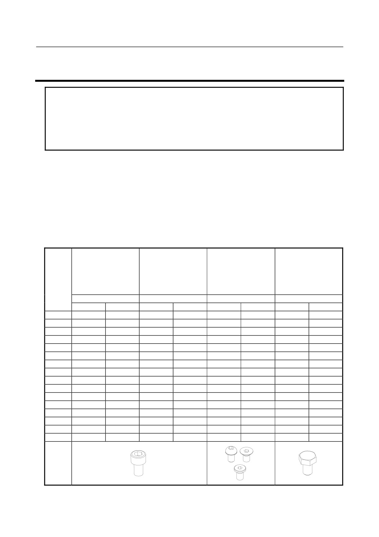
B STRENGTH OF BOLT AND BOLT TORQUE LIST
NOTE
When applying LOCTITE to the important bolt tightening points, make sure that it
is applied to the entire longitudinal portion in the engaging section of the female
threads. If it is applied to the male threads, the bolts may be loosened because
sufficient adhesion cannot be obtained. Remove the dust within the bolts and taps
and wipe oil off the engaging section. Make sure that there is no solvent in the
taps. Be sure to wipe the excess LOCTITE after tightening bolt.
Use bolt which strengths are below.
But if it is specified in text, obey it.
Hexagon socket head bolt made by steel
Size is M22 or less : Tensile strength 1200N/mm2 or more
Size is M24 or more : Tensile strength 1000N/mm2 or more
All size of bolt of the plating : Tensile strength 1000N/mm2 or more
Hexagon bolt, stainless bolt, special shape bolt (button bolt, low-head bolt, flush bolt .etc)
Tensile strength 400N/mm2 or more
If no tightening torque is specified for a bolt, tighten it according to this table.
Recommended bolt tightening torques
Unit: Nm
Hexagon socket head
button bolt
Hexagon socket head
Hexagon socket head
Hexagon socket head
Hexagon bolt
bolt
Nominal
bolt (stainless)
flush bolt
(steel)
(Steel)
diameter
Low-head bolt
(steel)
Tightening torque
Tightening torque
Tightening torque
Tightening torque
Upper limit
Lower limit
Upper limit
Lower limit
Upper limit
Lower limit
Upper limit
Lower limit
M3
1.8
1.3
0.76
0.53
――――
――――
――――
―――
M4
4.0
2.8
1.8
1.3
1.8
1.3
1.7
1.2
M5
7.9
5.6
3.4
2.5
4.0
2.8
3.2
2.3
M6
14
9.6
5.8
4.1
7.9
5.6
5.5
3.8
M8
32
23
14
9.8
14
9.6
13
9.3
M10
66
46
27
19
32
23
26
19
M12
110
78
48
33
――――
――――
45
31
(M14)
180
130
76
53
――――
――――
73
51
M16
270
190
120
82
――――
――――
98
69
(M18)
380
260
160
110
――――
――――
140
96
M20
530
370
230
160
――――
――――
190
130
(M22)
730
510
――――
――――
――――
――――
――――
――――
M24
930
650
――――
――――
――――
――――
――――
――――
(M27)
1400
960
――――
――――
――――
――――
――――
――――
M30
1800
1300
――――
――――
――――
――――
――――
――――
M36
3200
2300
――――
――――
――――
――――
――――
――――
- 124 -
B-82274EN/09
APPENDIX C.INSULATION ABOUT ARC WELDING ROBOT
C INSULATION ABOUT ARC WELDING
ROBOT
C.1 ABSTRACT
The arc welding robot performs welding, using a welding torch attached to its end effector via a bracket.
Because a high welding current flows through the welding torch, the insulation between the end effector
and torch is dualized.
If no due consideration is taken, a poor insulation caused by a pileup of spatter can allow the welding
current to leak into robot mechanical sections, possibly resulting in the motor being damaged or the
sheaths of cables in the mechanical sections melting.
C.2 INSULATION AT THE WRIST
-
Design the insulation between the end effector and welding torch so that no current will leak from
the end effector. Concretely, when fastening the insulating material inserted between the end
effector and torch bracket, use different bolts on the insulation material and torch bracket.
-
Insert the insulating material between the torch and torch bracket so that the insulation is dualized.
When installing the insulating material, be sure to set the crack in the torch holder away from that
of the insulating material to prevent spatter from getting in the cracks.
-
Insert the insulating material between the torch and torch bracket so that the insulation is dualized.
When installing the insulating material, be sure to set the crack in the torch holder away from that
of the insulating material to prevent spatter from getting in the cracks.
-
Allow a sufficient distance (at least 5 mm) at the insulating materials in case a pileup of spatter
should occur.
-
Even after the insulation is reinforced, it is likely that, if a pileup of spatter grows excessively,
current may leak. Periodically remove spatter when the robot is in service.
- 125 -