FANUC Series 0i-MODEL F Plus. CONNECTION MANUAL (FUNCTION) - page 352
 

  Index      Manuals     FANUC Series 0i-MODEL F Plus. CONNECTION MANUAL (FUNCTION) B-64693EN-1/01


Search            copyright infringement  


Content      ..     350      351      352      353     ..


FANUC Series 0i-MODEL F Plus. CONNECTION MANUAL (FUNCTION) - page 352


18. DIAGNOSIS FUNCTION


B-64693EN-1/01


- 2770 - 

18.4.4 

Trouble diagnosis monitor screen 

Outline 

Trouble diagnosis monitor screen displays information when the alarm is occurred necessary to diagnose 
the servo/spindle alarm. 
 
Servo/spindle  monitor  data  on "1-4 immediately before occurrence of the alarm" for four samplings 
immediately before and  "The latest alarm is occurred" can be displayed as data  when the alarm is 
occurred. 
Moreover, "Present" of servo/spindle monitor data when usually operating can be displayed. 
 

Display procedure of trouble diagnosis monitor screen (for 8.4/10.4-inch display 
unit) 

Procedure 

Press function key 


Press the continuous menu key 


  until soft key [MONIT] appears. 

Press soft key [MONIT]. 


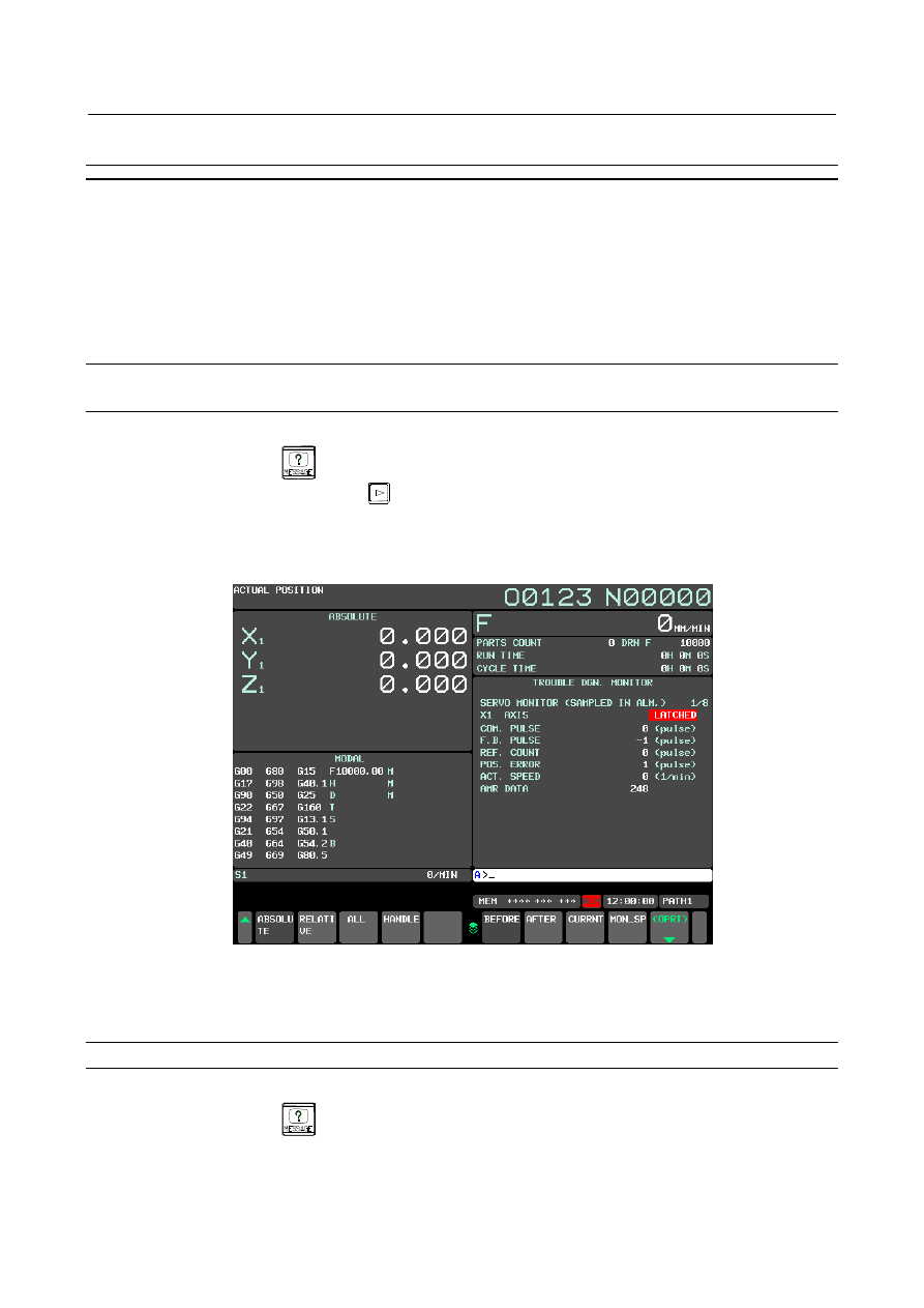
The following screen is sample of displaying data of X axis (servo) when the alarm occurred. 


Fig.18.4.4 (a) Trouble diagnosis monitor screen (10.4-inch display unit) 


The servo monitor data screen and the spindle monitor data screen can be switched by pushing soft 
key [MON_SP] / [MON_SV]. 


Display procedure of trouble diagnosis monitor screen (for 15/19-inch display unit) 

Procedure 

Press function key 


Press the vertical soft key [NEXT PAGE] until vertical soft key [MONIT] appears. 

Press the vertical soft key [MONIT]. 

The servo monitor data screen and the spindle monitor data screen can be switched by pushing the 
vertical soft key [MON_SP] / [MON_SV]. 

B-64693EN-1/01


18. DIAGNOSIS FUNCTION


- 2771 - 

Explanation 

- Data displayed in monitor Screen 

Displayed data in monitor screen is showed below. 
 

Table 18.4.4 (a) Data of servo motor 

Data (Unit) 

Data type 

Display range 

Data explanation 

Page 

number 

COMMAND PULSE (pulse) 

2 Word 

±

99999999 


F.B. PULSE (pulse) 

2 Word 

±

99999999 

(NOTE 3) 

REF.COUNTER (pulse) 

2 Word 

±

99999999 


POS. ERROR (pulse) 

2 Word 

±

99999999 


ACTUAL SPEED (1/min) 

Word 

-32768 to 
+32767 


AMR DATA 

Word 

0 to +255 

Data of pole position of the 
rotor “256” shows 360 degree 
as electrical angle 

TORQUE COMMAND (%) 

Word 

±

400 

Torque command. “100” 
shows maximum torque 

EFFECTIVE CURRENT (%) 

Word 

±

400 

“100” shows maximum 
current of amplifier 

MOTOR CURRENT (A) 

Word 

±

4096 


DISTURBANCE LEVEL (%) 

Word 

0 to +200 

“100” shows the alarm level 
of Unexpected disturbance 
torque detection function 

HEAT SIMULATION (%) 

Word 

0 to +100 

“100” shows the alarm level 
of OVC alarm. 

ARBITRARY DATA1 

Word 

-32768 to 
+32767 

(NOTE 2) 

ARBITRARY DATA2 

Word 

-32768 to 
+32767 

(NOTE 2) 

DC LINK VOLT. (V) 

Word 

0 to +1023 

Instantaneous value   
(NOTE 3) 

3 (NOTE 6) 

PS VOLTAGE RMS (Vrms) 

Word 

0 to +1023 

Average value during 1 cycle 
of power source (NOTE 3) 

3 (NOTE 6) 

PS VOLT.UMBALANCE (%) 

Word 

0 to +15.5 

Average value during 1 cycle 
of power source (NOTE 3) 

3 (NOTE 6) 

PS VOLTAGE THD (%) 

Word 

0 to +31.5 

Average value of THD(Total 
Harmonic Distortion) during 1 
cycle of power frequency 
(NOTE 3) 

3 (NOTE 6) 

PS CURRENT (A) 

Word 

0 to +2047 

Average value of current 
amplitude during 1 cycle of 
power source (NOTE 3) 

3 (NOTE 6) 

PS STATUS FLAG 1 

Bit 

0 / 1 

(NOTE 4) 

3 (NOTE 6) 

PS STATUS FLAG 2 

Bit 

0 / 1 

(NOTE 4) 

3 (NOTE 6) 

PS STATUS FLAG 3 

Bit 

0 / 1 

(NOTE 4) 

3 (NOTE 6) 

PS STATUS FLAG 4 

Bit 

0 / 1 

(NOTE 4) 

3 (NOTE 6) 

PS INPUT FREQ (Hz) 

Word 

0 to +102.3 

Average value during 1 cycle 
of power source (NOTE 3) 

3 (NOTE 6) 

SV INS.INFO. 

Byte 

0 to 3F 

Various status flags at using 
Leakage detection function 

4 (NOTE 6) 

SV INS.RESISTANCE (M

Ω

Word 

0 to +102.1 

Value of insulation resistance 
at using Leakage detection 
function (NOTE 3) 

4 (NOTE 6) 

PS INT.TMP. (

Byte 

0 to +255 

(NOTE 3) 

5 (NOTE 6) 

PS HEAT SINK TMP. (

Byte 

0 to +255 

(NOTE 3) 

5 (NOTE 6) 

18. DIAGNOSIS FUNCTION


B-64693EN-1/01


- 2772 - 

Data (Unit) 

Data type 

Display range 

Data explanation 

Page 

number 

SV INT.TMP. (

Byte 

0 to +255 

(NOTE 3) 

5 (NOTE 6) 

SV HEAT SINK TMP. (

Byte 

0 to +255 

(NOTE 3) 

5 (NOTE 6) 

AMP GROUP/SLAVE 

Byte 

0 to +255 

Group number and Slave 
number of power supply (PS) 

5 (NOTE 6) 

PS DGN.INFO. 

Word 

0 to FFFF 

Status flags of power 
supply(PS) 

5 (NOTE 6) 

AMP COMM.ERR.INF. 

Word 

0 to FFFF 

Error information flags for 
communication between 
amplifiers 

5 (NOTE 6) 

SV DGN.INFO. 

Word 

0 to FFFF 

Diagnosis flags for servo 
amplifier(SV) 

5 (NOTE 6) 

SV FSSB UPR.ERR. 

2Word 

0 to FFFF 

(NOTE 5) 

6 (NOTE 6) 

SV FSSB LWR.ERR. 

2Word 

0 to FFFF 

(NOTE 5) 

6 (NOTE 6) 

SV FSSB UPR.JTR. 

2Word 

0 to FFFF 

(NOTE 5) 

6 (NOTE 6) 

SV FSSB LWR.JTR. 

2Word 

0 to FFFF 

(NOTE 5) 

6 (NOTE 6) 

SDU FSSB UPR.ERR. 

2Word 

0 to FFFF 

(NOTE 5) 

6 (NOTE 6) 

SDU FSSB LWR.ERR. 

2Word 

0 to FFFF 

(NOTE 5) 

6 (NOTE 6) 

SDU FSSB UPR.JTR. 

2Word 

0 to FFFF 

(NOTE 5) 

6 (NOTE 6) 

SDU FSSB LWR.JTR. 

2Word 

0 to FFFF 

(NOTE 5) 

6 (NOTE 6) 

INT.DTCT.INTP.CNT 

Word 

0 to +65535 

The number of data 
interpolation when the 
feedback data of internal 
detector is disturbed by noise 

7 (NOTE 7) 

INT.DTCT.COM.CNT 

Word 

0 to +65535 

The number of 
communication error when 
the feedback data of internal 
detector is disturbed by noise 

7 (NOTE 7) 

INT.DETECTOR WRN. 

Word 

0 to FFFF 

Warning information of 
internal detector 

7 (NOTE 6) 

EXT.DTCT.INTP.CNT 

Word 

0 to +65535 

The number of data 
interpolation when the 
feedback data of external 
detector is disturbed by noise 

7 (NOTE 7) 

EXT.DTCT.COM.CNT 

Word 

0 to +65535 

The number of 
communication error when 
the feedback data of external 
detector is disturbed by noise 

7 (NOTE 7) 

EXT.DETECTOR WRN. 

Word 

0 to FFFF 

Warning information of 
external detector 

7 (NOTE 6) 

SV DATA 1 

Word 

-32768 to 
+32767 

(Note2) 

7 (NOTE 6) 

SV DATA 2 

Word 

-32768 to 
+32767 

(Note2) 

7 (NOTE 6) 

SV DATA 3 

Word 

-32768 to 
+32767 

(Note2) 

7 (NOTE 6) 

SV DATA 4 

Word 

-32768 to 
+32767 

(Note2) 

7 (NOTE 6) 


B-64693EN-1/01


18. DIAGNOSIS FUNCTION


- 2773 - 

NOTE 

1  The data range shows the range in which a data can be monitored in this 

function. It doesn’t show the system efficiency or rated value. 

2  ARBITRARY DATA1,2 and SV DATA1-4 are used for service operation by 

FANUC. 

3  The displayed values as Voltage, Current, Frequency, Resistance, and 

Temperature are approximate value and they have some error. If you want to 
know the precise values, measure them by exclusive equipments.   

4  PS STATUS FLAG1-4 are used for service operation by FANUC. 
5  FSSB ERROR and FSSB JITTER show the status of FSSB communication. 

They are used for service operation by FANUC. 

6  These items are not displayed in the system of G321 and 31 G331. 
7  These items are displayed on the 3 page in the system of G321 and G331. 


Table 18.4.4 (b) Data of spindle motor 

Data (Unit) 

Data type 

Display range 

Data explanation 

Page 

number 

OPERATION 

Character 

***** 


GEAR/OUT SEL 

Character 

***** 


COMMAND PULSE(pulse) 

2Word 

±

99999999 


COMMAND SPEED(1/min) 

Word 

-32768 to 
+32767 

(NOTE 2) 

CONTROL INPUT 

Character 

***** 


CONTROL OUTPUT 

Character 

***** 


ACT.SPINDLE SPEED (1/min)   

Word 

-32768 to 
+32767 


ACT.MOTOR SPEED (1/min)   

Word 

-32768 to 
+32767 

(NOTE 2) 

LOAD METER (%) 

Word 

0 to +10000 


TORQUE CMD(%) 

Word 

-100 to +100 

Torque command. “100” 
shows the maximum torque. 

2 (NOTE 7) 

MOTOR CURRENT (A) 

Word 

-4096 to +4095 


2 (NOTE 7) 

HEAT SIMU.(MOTOR) (%) 

Byte 

0 to +100 

“100” shows the alarm level 
of OVC alarm. 

2 (NOTE 7) 

HEAT SIMU.(AMP) (%) 

Byte 

0 to +100 

“100” shows the alarm level 
of OVC alarm. 

2 (NOTE 7) 

POS. ERROR (pulse) 

2Word 

±

99999999 


SYN ERR (pulse) 

2Word 

±

99999999 


DC LINK VOLT. (V) 

Word 

0 to +1023 

Instantaneous value (NOTE 
3) 

3 (NOTE 7) 

PS VOLTAGE RMS (Vrms) 

Word 

0 to +1023 

Average value during 1 cycle 
of power source (NOTE 3) 

3 (NOTE 7) 

PS VOLT.UMBALANCE (%) 

Word 

0 to +15.5 

Average value during 1 cycle 
of power source (NOTE 3) 

3 (NOTE 7) 

PS VOLTAGE THD (%) 

Word 

0 to +31.5 

Average value of THD(Total 
Harmonic Distortion) during 1 
cycle of power source (NOTE 
3) 

3 (NOTE 7) 

PS CURRENT (A) 

Word 

0 to +1023 

Average value of current 
amplitude during 1 cycle of 
power source (NOTE 3) 

3 (NOTE 7) 

PS STATUS FLAG 1 

Bit 

0 / 1 

(NOTE 5) 

3 (NOTE 7) 

PS STATUS FLAG 2 

Bit 

0 / 1 

(NOTE 5) 

3 (NOTE 7) 

PS STATUS FLAG 3 

Bit 

0 / 1 

(NOTE 5) 

3 (NOTE 7) 

18. DIAGNOSIS FUNCTION


B-64693EN-1/01


- 2774 - 

Data (Unit) 

Data type 

Display range 

Data explanation 

Page 

number 

PS STATUS FLAG 4 

Bit 

0 / 1 

(NOTE 5) 

3 (NOTE 7) 

PS INPUT FREQ (Hz) 

Word 

0 to +102.3 

Average value during 1 cycle 
of power source (NOTE 3) 

3 (NOTE 7) 

SP INS.INFO. 

Byte 

0 to 3F 

Various status flags at using   
Leakage detection function 
(NOTE 3) 

4 (NOTE 7) 

SP INS.RESISTANCE (M

Ω

Word 

0 to +102.1 

Value of insulation resistance 
at using Leakage detection 
function (NOTE 3) 

4 (NOTE 7) 

PS INT.TMP. (

Byte 

0 to +255 

(NOTE 3) 

5 (NOTE 7) 

PS HEAT SINK TMP. (

Byte 

0 to +255 

(NOTE 3) 

5 (NOTE 7) 

SP INT.TMP. (

Byte 

0 to +255 

(NOTE 3) 

5 (NOTE 7) 

SP HEAT SINK TMP. (

Byte 

0 to +255 

(NOTE 3) 

5 (NOTE 7) 

AMP GROUP/SLAVE 

Byte 

0 to +255 

Group number and Slave 
number of power supply (PS) 

5 (NOTE 7) 

PS DGN.INFO. 

Word 

0 to FFFF 

Status flags of power 
supply(PS) 

5 (NOTE 7) 

AMP COMM.ERR.INF. 

Word 

0 to FFFF 

Error information flags for 
communication between 
amplifiers 

5 (NOTE 7) 

SP DGN.INFO. 

Word 

0 to FFFF 

Diagnosis flags for spindle 
amplifier(SP) 

5 (NOTE 7) 

SP FSSB UPR.ERR. 

2Word 

0 to FFFF 

(NOTE 6) 

6 (NOTE 7) 

SP FSSB LWR.ERR. 

2Word 

0 to FFFF 

(NOTE 6) 

6 (NOTE 7) 

SP FSSB UPR.JTR. 

2Word 

0 to FFFF 

(NOTE 6) 

6 (NOTE 7) 

SP FSSB LWR.JTR. 

2Word 

0 to FFFF 

(NOTE 6) 

6 (NOTE 7) 

INT.A/B AMPLITUDE (V) 

Byte 

0 to +2.55 

Amplitude of internal analog 
sensor 

7 (NOTE 7) 

INT.A/B MAX FLUCT (mV) 

Byte 

0 to +1270 

Maximum fluctuation ratio of 
internal analog sensor 

7 (NOTE 7) 

INT.A/B OFFSET A (mV) 

Byte 

-1280 to +1270 

Offset of A-phase of internal 
analog sensor 

7 (NOTE 7) 

INT.A/B OFFSET B (mV) 

Byte 

-1280 to +1270 

Offset of B-phase of internal 
analog sensor 

7 (NOTE 7) 

INT.A/B NOISE CNT 

Word 

-32768 to 
+32767 

The number of noise when 
the feedback data of internal 
analog sensor is disturbed 

7 (NOTE 7) 

EXT.A/B AMPLITUDE (V) 

Byte 

0 to +2.55 

Amplitude of external analog 
sensor 

7 (NOTE 7) 

EXT.A/B MAX FLUCT (mV) 

Byte 

0 to +1270 

Maximum fluctuation ratio of 
external analog sensor 

7 (NOTE 7) 

EXT.A/B OFFSET A (mV) 

Byte 

-1280 to +1270 

Offset of A-phase of external 
analog sensor 

7 (NOTE 7) 

EXT.A/B OFFSET B mV) 

Byte 

-1280 to +1270 

Offset of B-phase of external 
analog sensor 

7 (NOTE 7) 

EXT.A/B NOISE CNT 

Word 

-32768 to 
+32767 

The number of noise when 
the feedback data of external 
analog sensor is disturbed 

7 (NOTE 7) 

INT.SRAL INTP.CNT 

Word 

0 to +65535 

The number of data 
interpolation when the 
feedback data of internal 
serial sensor is disturbed by 
noise 

8 (NOTE 7) 

B-64693EN-1/01


18. DIAGNOSIS FUNCTION


- 2775 - 

Data (Unit) 

Data type 

Display range 

Data explanation 

Page 

number 

INT.SRAL COM.CNT 

Word 

0 to +65535 

The number of 
communication error when 
the feedback data of internal 
serial sensor is disturbed by 
noise 

8 (NOTE 7) 

INT.SRAL WRN. 

Word 

0 to FFFF 

Warning information of 
internal serial sensor 

8 (NOTE 7) 

EXT.SRAL INTP.CNT 

Word 

0 to +65535 

The number of data 
interpolation when the 
feedback data of external 
serial sensor is disturbed by 
noise 

8 (NOTE 7) 

EXT.SRAL COM.CNT 

Word 

0 to +65535 

The number of 
communication error when 
the feedback data of external 
serial sensor is disturbed by 
noise 

8 (NOTE 7) 

EXT.SRAL WRN. 

Word 

0 to FFFF 

Warning information of 
external serial sensor 

8 (NOTE 7) 

SP DATA 1 

Word 

-32768 to 
+32767 

(NOTE 4) 

8 (NOTE 7) 

SP DATA 2 

Word 

-32768 to 
+32767 

(NOTE 4) 

8 (NOTE 7) 

SP DATA 3 

Word 

-32768 to 
+32767 

(NOTE 4) 

8 (NOTE 7) 

SP DATA 4 

Word 

-32768 to 
+32767 

(NOTE 4) 

8 (NOTE 7) 


NOTE 

1  The data range shows the range in which a data can be monitored in this 

function. It doesn’t show the system efficiency or rated value. 

2  To display COMMAND SPEED and ACTUAL MOTOR SPEED, it’s necessary to 

set following parameters. 
-  No.4020 : Maximum motor speed of main spindle   
-  No.4196 : Maximum motor speed of sub spindle   
 

(in case of using Spindle switching control) 

3  The displayed values as Voltage, Current, Frequency, Resistance, and 

Temperature are approximate value and they have some error. If you want to 
know the precise values, measure them by exclusive equipments. 

4  SP DATA1-4 are used for service operation by FANUC 
5  PS STATUS FLAG1-4 are used for service operation by FANUC. 
6  FSSB ERROR and FSSB JITTER show the status of FSSB communication. 

They are used for service operation by FANUC. 

7  These items are not displayed in the system of G321 and G331. 


Table 18.4.4 (c) Data of others 

Data 

Data form 

Page 

number 

The latest latch date 

Year (Two last digits) / Month (Two digits) / Day (Two digits) 

8 (servo), 
9 (spindle) 

The latest latch time 

Hour (Two digits) / Minute (Two digits) / Second (Two digits) 

Executed file name at latched 

Character 

Executed N number at latched 

N+ number of five digits 

18. DIAGNOSIS FUNCTION


B-64693EN-1/01


- 2776 - 

Operation 

- Servo monitor data screen 


Fig.18.4.4 (b) Trouble diagnosis monitor screen (Servo monitor data) (10.4-inch display unit) 

 
Servo monitor data can be selected by pressing soft key [NEW]/[CURRNT]/[BEFORE]/[AFTER]. 
Soft key [NEW] and [CURRNT] is displayed alternately. 
Moreover, Soft key [BEFORE]/[AFTER]  is displayed to press  soft  key  [NEW], and if soft  key 
[CURRNT] is pressed, it is not displayed. 


TIME 

Present 

When alarm is 

occurred 

Before 

After 

1-4 immediately before 

occurrence of the alarm 


Soft key [NEW] 

: Servo monitor data when the alarm is occurred is displayed. 

Soft key [CURRNT] 

: Present servo monitor data is displayed. 

Soft key [BEFORE] 

: When the alarm is occurred and status display changes into [LATCHED] state, 
data before four samplings immediately before occurrence of the alarm is 
preserved in CNC.  Preserved servo monitor data changes and is displayed by 
pressing this soft key as "SAMPLED IN ALM"

"BEFORE ALM 1"

"BEFORE ALM 2"

"BEFORE ALM 3"

"BEFORE ALM 4". 

Soft key [AFTER] 

: As well as the above operation, Preserved servo monitor data changes and is 
displayed by pressing this soft key as "BEFORE ALM 4"

"BEFORE ALM 3"

"BEFORE ALM 2"

"BEFORE ALM 1"

"SAMPLED IN ALM". 

Soft key [MON_SP] 

: Spindle monitor data screen is displayed. 


NOTE 


Monitor data of 1 - 4 samplings immediately before occurrence of the alarm is not 
displayed since 4 pages. 

B-64693EN-1/01


18. DIAGNOSIS FUNCTION


- 2777 - 

- Spindle monitor data screen 


Fig.18.4.4 (c) Trouble diagnosis monitor screen (Spindle monitor data) (10.4-inch display unit) 

 
Spindle monitor data can be selected by pressing soft key [NEW]/[CURRNT]/[BEFORE]/[AFTER]. 
Soft key [NEW] and [CURRNT] is displayed alternately. 
Moreover, Soft key [BEFORE]/[AFTER]  is displayed to press  soft  key  [NEW], and if soft  key 
[CURRNT] is pressed, it is not displayed. 


TIME 

Present 

When alarm is 

occurred 

Before 

After 

1-4 immediately before 

occurrence of the alarm 


Soft key [NEW] 

: Spindle monitor data when the alarm is occurred is displayed. 

Soft key [CURRNT] 

: Present Spindle monitor data is displayed. 

Soft key [BEFORE] 

: When the alarm is occurred and status display changes into [LATCHED] state, 
data before four samplings immediately before occurrence of the alarm is 
preserved in CNC. Preserved Spindle monitor data changes and is displayed by 
pressing this soft key as "SAMPLED IN ALM"

"BEFORE ALM 1"

"BEFORE ALM 2"

"BEFORE ALM 3"

"BEFORE ALM 4". 

Soft key [AFTER] 

: As well as the above operation, Preserved Spindle monitor data changes and is 
displayed by pressing this soft key as "BEFORE ALM 4"

"BEFORE ALM 3"

"BEFORE ALM 2"

"BEFORE ALM 1"

"SAMPLED IN ALM". 

Soft key [MON_SV] 

: Servo monitor data screen is displayed. 


NOTE 


Spindle monitor data that can the above operation is only an item from page 2 to 
page 3. 
The value is displayed in the item on page 1 and since 4 pages of the spindle 
monitor data screen the value at present when status display is [SAMPLING], or 
the value at the alarm is occurred when status display is [LATCHED]. 


Content      ..     350      351      352      353     ..