FANUC Series 0i-MODEL F Plus. CONNECTION MANUAL (FUNCTION) - page 333
 

  Index      Manuals     FANUC Series 0i-MODEL F Plus. CONNECTION MANUAL (FUNCTION) B-64693EN-1/01


Search            copyright infringement  


Content      ..     331      332      333      334     ..


FANUC Series 0i-MODEL F Plus. CONNECTION MANUAL (FUNCTION) - page 333


16. PMC CONTROL FUNCTION


B-64693EN-1/01


- 2618 - 


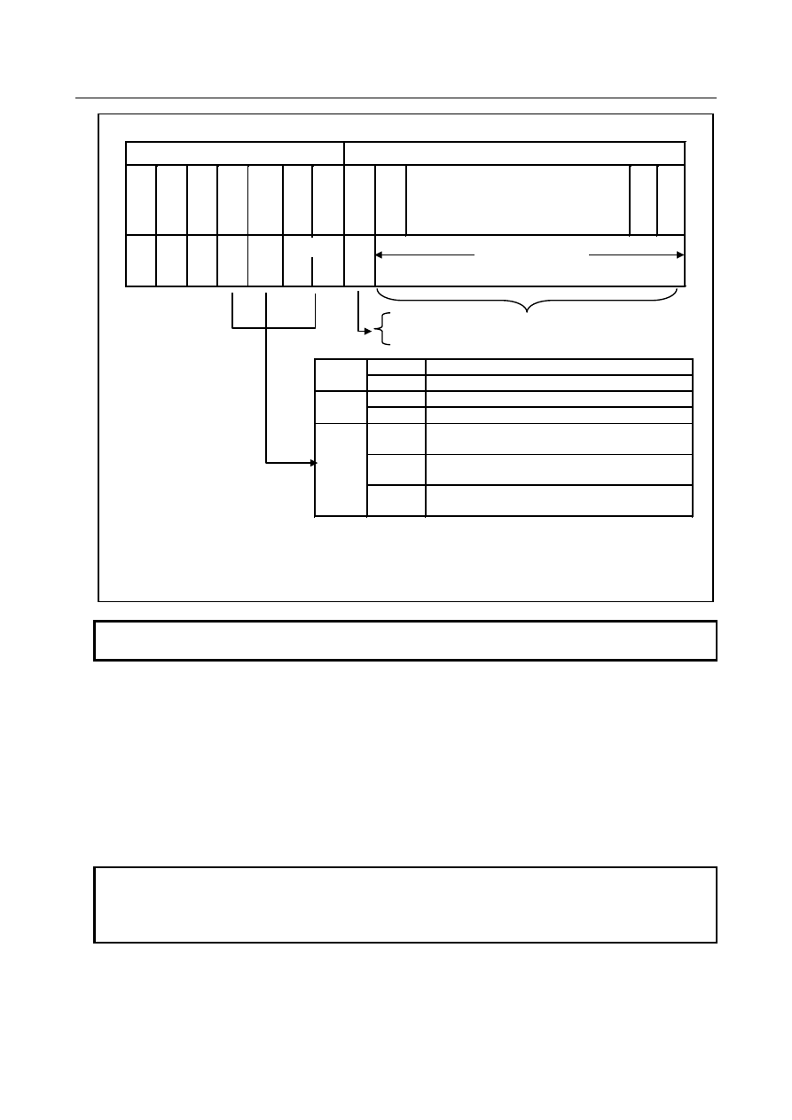
Data specification for external tool offset (For T series) 

Address 

Data 

*Note


31 

30 

. . . 

E

E

a/i 


g/w 


Sign 


0: +  Specified by BCD 8-digit code 


1: 

-


(0 to +/

79999999)


*Note


Incremental specification 

a/i 

Absolute specification 

Specification of tool wear offset value 

g/w 

Specification of tool geometry offset value 

EA1=0, 
EA0=0 

Specification of X axis offset 

EA1=0, 
EA0=1 

Specification of Z axis offset 

X/Z/R 

EA1=1, 
EA0=0 

Specification of tool nose radius 
compensation value 


*Note

: If the bit 3 (EED) of parameter No.6301 is set to 0, the offset value is specified by using signals 

ED0 to ED14, the sign is decided by the signal ED15. 


The range of data is available to specify the data from 0 to +/- 7999. 

Offset value 

X/Z/R 


NOTE 

The Y-axis offset cannot be specified. 


  - 

External workpiece coordinate system shift 

In the external workpiece coordinate system shift, the shift value can be externally modified by the signal 
of PMC. 
Each axis has this shift value (parameter No. 1220), and this shift value is added to all the workpiece 
coordinate systems in common.   
The shift value is not lost by cutting off the power supply. 
The shift value can not only be added to the current work coordinate system shift but also be substituted 
for the current value. 
The value range is 0 to + / - 79999999. 
The unit and setting range are the same as the Tool offset. 
 

NOTE 


If bit 3 (EED) of parameter No. 6301 is set to 1, the data area can be specified 
by 32bit data specification. 
Under the setting, the external tool compensation range is up to +/ - 79999999. 

B-64693EN-1/01


16. PMC CONTROL FUNCTION


- 2619 - 

  - 

External machine zero point shift 

The machine coordinate system can be externally shifted by inputting a shift value. 
When the shift value is input, compensation is immediately applied to the corresponding axis and the axis 
moves. The position accuracy can be improved by combining this function with sensors. 
The specification to shift the axis is the same as the external workpiece coordinate system shift. 
The compensation value is specified in signals ED0 to ED15 using a binary code ranging from 0 to 

±

9999. 

This compensation value must be specified in absolute value. The value which the machine actually 
moves at input is the difference from the previously stored value. 
After the Reference point is established, this function becomes effective. The shift amount is memorized 
though the machine is not moved when the shift amount is input before the Reference point is established. 
When the Reference point is established afterwards, the machine is moved for the memorized shift 
amount. 
 

NOTE 


If bit 7 (EEX) of parameter No. 6300 is set to 1, the Data area can be specified 
by 32bit data specification. 
Under the setting, the external machine zero point shift range is up to +/ - 
999999999. 


  CAUTION 


When a large value of compensation is applied at one time, an alarm such as 
"excessive error on stop" may occur. In this case, input the compensation in 
several smaller increments. 


  - 

External message 

(a)  External alarm message 
 

By sending alarm number from PMC, the CNC is brought to an alarm status; an alarm message is 
sent to the CNC, and the message is displayed on the screen of the CNC. 


Reset of alarm status is also done with external data. 


Up to 4 alarm numbers (16 alarm numbers when bit 1 (M16) of parameter No. 11931 is set to 1) and 
messages can be sent at a same time. A message consisting of up to 63 ASCII characters can be sent 
for one alarm number. 


In case of using a multi-path system, the alarm will be set separately for each path. 


Also the alarm is set separately for one. 


It is available to select the range of alarm number and the display form by setting the bit 0 (EXA) of 
parameter No. 6301. 
Bit 0 (EXA) of parameter No. 6301 = 0 

Alarm number 0 to 999 can be sent. To distinguish these alarms from other alarms, the CNC 
displays them by adding 1000 to an alarm number.   

Bit 0 (EXA) of parameter No. 6301 = 1 

Alarm number 0 to 4095 can be sent. The CNC displays them with prefix characters “EX” to an 
alarm number for display. 


16. PMC CONTROL FUNCTION


B-64693EN-1/01


- 2620 - 

(b)  External operator message 
 

Message to the operator is given by the signal of PMC, and the message is displayed. 


The operator messages can be cleared by external data. 


Up to 4 message numbers (bit 1 (M16) of parameter No. 11931) can be sent at a same time. Up to 
256 characters can be sent in an operator message. 


In case of using a multi-path system, the operator message is common resource for plural path of 
machine group. It is set each machine group. It is available to display the operator message by using 
the primary path signal of machine group. 


It is available to select the range of message number and the display form by setting the bit 1 (EXM) 
of parameter No. 6301. 
Bit 1 (EXM) of parameter No. 6301 = 0 
 

The message numbers 0 to 999 can be sent.   


The message numbers 0 to 99 are displayed along with the message. 


To distinguish these alarms from other alarms, the CNC displays them by adding 2000 to an 
alarm number.   


When a message from 100 to 999 is displayed, the message number is not displayed; only its 
text is displayed. 

Bit 1 (EXM) of parameter No. 6301 = 1 
 

The message numbers 0 to 4095 can be sent.   


The message numbers 0 to 99 are displayed along with the message. 


The CNC displays them with prefix characters "EX" to an alarm for display. 


When a message number from 100 to 4095 is displayed, the message number is not displayed; 
only its text is displayed. 


Data specification method in external message 
 

Table 16.2 (d) 

Item 

EA6


EA5 

EA4 

EA3 

EA2 

EA1 

EA0 

ED15 to ED0(binary)


Alarm set 

Alarm No. 

Alarm clear 

Alarm No. 

Operator message list 

Message No. 

Operator message clear 

Message No. 

Message 

1


Character(Note)


NOTE 


Two characters are sent at a time   


  (See ISO code given in the table below.) 


ED15 to ED8 . . . . . . . Character code in 1st character 


ED7 to ED0 . . . . . . . . Character code in 2nd character   


When sending only one character, fill the second slot with a code smaller than 
20 and it will be ignored. 


B-64693EN-1/01


16. PMC CONTROL FUNCTION


- 2621 - 


Fig. 16.2 (d) 


  - 

Substitution of the number of required parts and number of machined parts 

Substitution is possible for the number of parts required and the number of parts machined. 
 

Data specification for No. of parts required and No. of parts 

machined. 

Address 

Data 


15 


........... 

0  0/1 

MSB


LSB 

Value of parts no. 


 (1)              (2)           (3) 

(1)  Set to 110000 
(2)  0: No. of parts required 
 

1: No. of parts machined 

(3)  BCD 4-digit code (0000 to 9999)


Signals 

Address signals for external data input EA0 to EA6 <Gn002.6 – Gn002.0> 

  [Classification]  Input signal 
 

[Function]  These signals indicate the type of the entered data. 


16. PMC CONTROL FUNCTION


B-64693EN-1/01


- 2622 - 

Data signals for external data input ED0 to ED31 <Gn211, Gn210,Gn000, Gn001> 

  [Classification]  Input signal 
 

[Function]  These signals indicate the entered data. 

The use of the 32 code signals (16 code signals) varies with the data type. 


Read signal for external data input ESTB <Gn002.7> 

  [Classification]  Input signal 
 

[Function]  The signal reports that the address and data are set in external data input. 

When the signal is set to “1”, the control unit reads the address and data for external data 
input. 


Read completion signal for external data input EREND <Fn060.0> 

  [Classification]  Output signal 
 

[Function]  This signal reports that the control unit has finished reading the entered data. 


Search completion signal for external data input ESEND <Fn060.1> 

  [Classification]  Output signal 
 

[Function]  This signal report that program number search, specified by external data input, has been 

completed. 


[Output cond.]  This signal is set to “1” when: 

The program number search specified by external data input is completed. 

The signal is set to “0” when: 

An automatic operation is started. 

A reset occurs. 


Search cancel signal for external data input ESCAN<Fn060.2> 

  [Classification]  Output signal 
 

[Function]  This signal notifies PMC of the cancellation of a program number search.   


[Output cond.]  When a reset is input between the time read signal for external data input ESTB is input 

and the time a search is executed in the external program number search function, if bit 3 
(ESC) of parameter No. 6300 is 1, the search is not executed. At this time, the control unit 
sets search cancel signal for external data input ESCAN to “1” instead of setting search 
completion signal for external data input ESEND to “1”. 


NOTE 


This signal is enabled when bit 3 (ESC) of parameter No. 6300 is 1. 


Signal address 


#7 

#6 

#5 

#4 

#3 

#2 

#1 

#0 

Gn000 


ED7 

ED6 

ED5 

ED4 

ED3 

ED2 

ED1 

ED0 


Gn001 


ED15 

ED14 

ED13 

ED12 

ED11 

ED10 

ED9 

ED8 


Gn002 


ESTB 

EA6 

EA5 

EA4 

EA3 

EA2 

EA1 

EA0 


Gn210 


ED23 

ED22 

ED21 

ED20 

ED19 

ED18 

ED17 

ED16 


Gn211 


ED31 

ED30 

ED29 

ED28 

ED27 

ED26 

ED25 

ED24 


#7 

#6 

#5 

#4 

#3 

#2 

#1 

#0 

Fn060 


ESCAN 

ESEND 

EREND 


B-64693EN-1/01


16. PMC CONTROL FUNCTION


- 2623 - 

Parameter 


#7 

#6 

#5 

#4 

#3 

#2 

#1 

#0 

6300 


EEX 


ESR 

ESC 


[Input type]  Parameter input 


[Data type]  Bit path 


#3  ESC

  When a reset is input between the input of the external data input read signal ESTB and 

the execution of a search, the external program number search function: 
0: 

Performs a search. 

1: 

Does not perform a search. 


#4  ESR

  The external program number search function is: 

0: 

Disabled. 

1: 

Enabled. 


#7  EEX

  PMC EXIN function 

0: 

Conventional specifications 

1: 

Extended specifications 

If you want to use external machine coordinate system shift which handles 

±

10.000 or 

more shift unavailable with the PMC/EXIN command in the conventional specifications, 
set 1. 
When this function is used for a multi-path system, the setting for path 1 is used. 
For details of EXIN and how to change ladder software, refer to the PMC manuals. 


#7 

#6 

#5 

#4 

#3 

#2 

#1 

#0 

6301 


EED 

NNO 

EXM 

EXA 


[Input type]  Parameter input 


[Data type]  Bit machine group 


#0  EXA

  This bit selects an external alarm message specification. 

0: 

A message number from 0 to 999 can be sent. When displaying an alarm number, 
the CNC prefixes the character string "EX" to the alarm number obtained by adding 
1000 to the message number

.


1: 

A message number from 0 to 4095 can be sent. The CNC prefixes the character 
string "EX" to a alarm number for display. 


#1  EXM

  This bit selects an external operator message specification. 

0: 

A message number from 0 to 999 can be sent. The message of a message number 
from 0 to 99 is displayed together with its number. The CNC adds 2000 to a number 
for distinction. A message number from 100 to 999 is not displayed on the screen, 
but only the corresponding message is displayed on the screen. 

1: 

A message number from 0 to 4095 can be sent. The message of a message number 
from 0 to 99 is displayed together with its number. The CNC prefixes the character 
string "EX" to a message number for display. A message number from 100 to 4095 
is not displayed on the screen, but only the corresponding message is displayed on 
the screen. 


#2  NNO

  When operator messages are set by external data input, a new line operation between one 

message set with a number and another message set with a different number is: 
0: 

Performed. 

1: 

Not performed. 


16. PMC CONTROL FUNCTION


B-64693EN-1/01


- 2624 - 


#3  EED

  To specify data for external tool compensation and external workpiece coordinate system 

shift, use: 
0: 

Signals ED15 to ED0. 
(The value which can be specified for tool compensation and workpiece coordinate 
system shift is from 0 to 

±

7999.) 

1: 

Signals ED31 to ED0.   
(The value which can be specified for tool compensation and workpiece coordinate 
system shift is from 0 to 

±

79999999.) 


6310 


Setting for number addition to external operator messages 


NOTE 


When this parameter is set, the power must be turned off before 
operation is continued. 


[Input type]  Parameter input 


[Data type]  Word machine group 

[Valid data range]  0 to 4096 

This parameter sets the number of messages to which message numbers are to be prefixed 
in external operator message display. 
When 0 is set, the same operation as when 100 is set is performed. 


[Example]  When 500 is set in this parameter, the messages of message numbers 0 to 499 are 

displayed together with their numbers on the screen. A message number of 500 and up is 
not displayed on the screen, but only the corresponding message is displayed on the 
screen. 


#7 

#6 

#5 

#4 

#3 

#2 

#1 

#0 

11931 


M16 


[Input type]  Parameter input 


[Data type]  Bit 


NOTE 


When this parameter is set, the power must be turned off before 
operation is continued. 


#1  M16

  In the external data input and external messages, the maximum number of external alarm 

messages and external operator messages that can be displayed is: 
0: 

4. 

1: 

16. 


3467 


Selection of the target folder among initial folders 


[Input type]  Parameter input 


[Data type]  Byte path 

[Valid data range]  0 to 7, 11 to 20 

This parameter selects a folder to be used for the external workpiece number search 
function, external program number  search function, and macro executor program 
reference and write function among the following initial folders: 
0: 

No specification 

1: 

Root folder 

(//CNC_MEM) 

2: 

System folder 

(//CNC_MEM/SYSTEM) 

3: 

MTB-dedicated folder 1  (//CNC_MEM/MTB1) 

4:   

MTB-dedicated folder 2  (//CNC_MEM/MTB2) 

B-64693EN-1/01


16. PMC CONTROL FUNCTION


- 2625 - 

5: 

User folder 

(//CNC_MEM/USER) 

6: 

Path folder 

(//CNC_MEM/USER/PATHn)


(Note) 


(NOTE)  PATHn: n is the selected path number (1 to the maximum number of 

paths). 

7: 

Common program folder (//CNC_MEM/USER/LIBRARY) 

8 to 10:  Not specified. 
11: 

Path 1 folder 

(//CNC_MEM/USER/PATH1) 

12: 

Path 2 folder 

(//CNC_MEM/USER/PATH2) 

13: 

Path 3 folder 

(//CNC_MEM/USER/PATH3) 

14: 

Path 4 folder 

(//CNC_MEM/USER/PATH4) 

 
When “0: No specification” is selected, the following folder is used for each function: 


External program number search function 


External workpiece number search function 
(Default foreground folder) 


Macro executor program reference and write function 
(Default background folder) 


NOTE 


Any user-created folder cannot be specified. 


For example, assume that a user folder named PATH3 is created 
in //CNC_MEM/USER in a 2-path system. User-created folder 
//CNC_MEM/USER/PATH3 cannot be specified by specifying 13 in 
this parameter. 


Alarm and message 

Number 

Message 

Description 

DS0059 

SPECIFIED NUMBER NOT 
FOUND 

The No. specified for a program No. or sequence No. search could 
not be found. 
There was an I/O request issued for a pot No. or offset (tool data), 
but either no tool numbers have been input since power ON or there 
is no data for the entered tool No. 

DS0131 

TOO MANY MESSAGE 

An attempt was made to display an external operator message or 
external alarm message, but five or more displays were required 
simultaneously. 

DS0132 

MESSAGE NUMBER NOT 
FOUND 

An attempt to cancel an external operator message or external 
alarm message failed because the specified message number was 
not found. 

DS0133 

TOO LARGE NUMBER 

A value other than 0 to 4095 was specified as the external 
operator message or the external alarm message number. 

DS1120 

UNASSIGNED ADDRESS 
(HIGH) 

The upper 4 bits (EIA4 to EIA7) of an external data I/O 
interface address signal are set to an undefined address 
(high bits). 

DS1121 

UNASSIGNED ADDRESS 
(LOW) 

The lower 4 bits (EIA0 to EIA3) of an external data I/O interface 
address signal are set to an undefined address (low bits). 

DS1128 

DI.EIDLL OUT OF RANGE 

The numerical value input by external data input signals EID0 
to EID31 has exceeded the permissible range. 

DS1130 

SEARCH REQUEST NOT 
ACCEPTED 

No requests can be accepted for a program No. or a sequence No. 
search as the system is not in the memory mode or the reset state. 

DS1131 

EXT-DATA ERROR (OTHER) 

[External Data I/O] 

An attempt was made to input tool data for tool offset by a tool No. 
during loading by the G10 code. 


Content      ..     331      332      333      334     ..