FANUC Series 0i-MODEL F Plus. CONNECTION MANUAL (FUNCTION) - page 310
 

  Index      Manuals     FANUC Series 0i-MODEL F Plus. CONNECTION MANUAL (FUNCTION) B-64693EN-1/01


Search            copyright infringement  


Content      ..     308      309      310      311     ..


FANUC Series 0i-MODEL F Plus. CONNECTION MANUAL (FUNCTION) - page 310


15. MEASUREMENT


B-64693EN-1/01


- 2434 - 

15 

MEASUREMENT 

15.1 

TOOL LENGTH MEASUREMENT 

M


Overview 

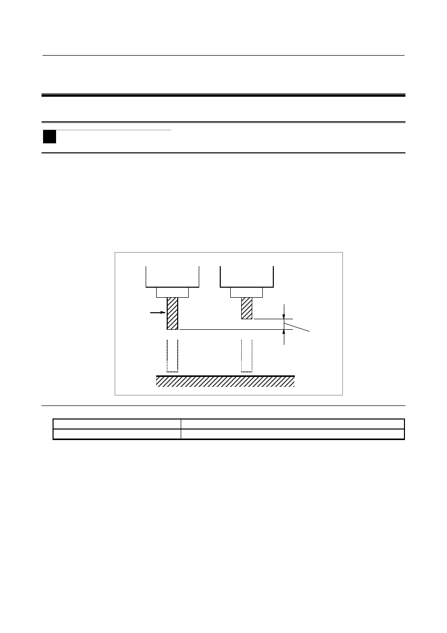
The value displayed as a relative and machine position can be set in the offset memory as an offset value 
by a soft key. 
Switch to the offset value display screen on the screen. Relative positions are also displayed on this 
screen. Then select the reference tool and set it at the fixed point on the machine by manual operation. 
Reset the displayed relative position to zero. Set the tool for measurement at the same fixed point on the 
machine by manual operation. The relative position display at this point shows difference between the 
reference tool and the tool measured and the relative position display value is then set as offset amounts.   
Another way is to display machine positions and compensate by inputting adjustment values. 


This difference 
is set as offset 
amount 

Fixed point 

Reference 
tool 


Reference item 

Manual name 

Item name 

OPERATOR’S MANUAL (B-64694EN) 

Tool length compensation 


B-64693EN-1/01


15. MEASUREMENT


- 2435 - 

15.2 

AUTOMATIC TOOL LENGTH MEASUREMENT (M SERIES) 
/ AUTOMATIC TOOL OFFSET (T SERIES) 

Overview 

When a tool is moved to the measurement position by execution of a command given to the CNC, the 
CNC automatically measures the difference between the current coordinate value and the coordinate 
value of the command measurement position and uses it as the offset value for the tool. When the tool has 
been already offset, it is moved to the measurement position with that offset value.   
The difference between the coordinate value of a measuring position and a specified coordinate value is 
added to current compensation. 


Compensation = (Current compensation) + [(Coordinate at tool stop) - (Coordinate at 
specification of measuring position)] 

Measurement 
speed 

A (start position) 
G37 for specifying measuring position 

B (deceleration position) 

C (measuring position)


Tool stops when measuring position 
reached signal goes on. 

Rapid traverse 


Format 

M


Hxx ; 

Specifies an offset number for tool length compensation.


G90 G37 

IP

_ ; 

Automatic tool length measurement. Absolute programming. 
G37 is valid only in the block in which it is specified. 
IP_ indicates the X-, Y-, Z-, or fourth axis. 


T


Txx ; 

Specifies an offset number for


tool position compensation.


G36 X_ ; or G37 Z_ ; 

Automatic tool offset. Absolute programming. 
G36 and G37 are valid only in the block in which it is specified.


15. MEASUREMENT


B-64693EN-1/01


- 2436 - 

Signal 

Measuring position reached signals 


XAE1

#1

<X0004.0>, XAE2

#1

<X0004.1> (M/T series), XAE3

#1

<X0004.2> (M series only) 


XAE1

#2

<X0013.0>, XAE2

#2

<X0013.1> (M/T series), XAE3

#2

<X0013.2> (M series only) 


XAE1

#3

<X0011.0>, XAE2

#3

<X0011.1> (M/T series), XAE3

#3

<X0011.2> (M series only) 


GAE1<Gn517.0>,GAE2<Gn517.1>, GAE3<Gn517.2> (M/T series) 

    [Classification]  Input signal 
 

  [Function]  If the measuring position specified by a program command differs from the measuring 

position which a tool has reached in practice, that is, the position at the moment the 
measuring position reached signal has just been turned “1”, the difference in the 
coordinate value is added to the current tool compensation value to update the 
compensation value. The tool is first fed to the specified measuring position by rapid 
traverse in a block where one of the following commands has been specified: 
G37 (Mseries) 
G36,G37 (Tseries) (G37.1, G37.2 if the bit 6 (MDC) of parameter No. 6210 is set to 1) 
The tool decelerates and temporarily stops at the distance 

g

 before the measuring position. 

The tool then moves to the measuring position at the speed preset by a parameters Nos. 
6241 to 6243. If the measuring position reached signal corresponding to the G code is 
turned “1” after the tool has approached within distance 

e

 of the measuring position and 

before the tool overshoots the measuring position by distance 

e

, the control unit updates 

the compensation value and terminates the move command for the block.   
If the measuring position reached signal is not turned “1” even after the tool has overshot 
the measuring position by distance 

e

, the control unit enters an alarm state and terminates 

the move command for the block without updating the compensation value. 


Start 
point 

Presumed measuring position 

e


e


g


S (xs, zs) 

X, Z 

F

R


F

P


|xa-xs|. |za-zs| 

U (xa, za) 

FR  :  Rapid traverse 
FP  :  Parameters Nos.6241 to 6243

feedrate


g


:  Parameters Nos.6251 to 6253 

e


:  Parameters Nos.6254 to 6256 

Measuring position 
reached signal 


B-64693EN-1/01


15. MEASUREMENT


- 2437 - 

Command code 

Axis specification 

Signal input 

Valid parameters 

T series 

M series 

T series 

M series 

T series 

M series 

G36 

(bit 3 (G36) of 

parameter No. 

3405=0) 

Basic 1st 

axis 


XAE1 

or 

GAE1 


6241, 
6251, 

6254 


G37 

(bit 3 (G36) of 

parameter No. 

3405=0) 

Basic 3rd 

axis 

Basic1st 

to 3rd 

axes 

XAE2 

or 

GAE2 

XAE1 to 

XAE3 

or 

GAE1 to 

GAE3 

6242, 
6252, 

6255 

6241 to 

6243, 

6251 to 

6253, 

6254 to 

6256 

G37.1 

(bit 3 (G36) of 

parameter No. 

3405=1) 

Basic 1st 

axis 

Basic 1st 

axis 

XAE1 

or 

GAE1 

XAE1 

or 

GAE1 

6241, 
6251, 

6254 

6241, 
6251, 

6254 

G37.2 

(bit 3 (G36) of 

parameter No. 

3405=1) 

Basic 3rd 

axis 

Basic 2nd 

axis 

XAE2 

or 

GAE2 

XAE2 

or 

GAE2 

6242, 
6252, 

6255 

6242, 
6252, 

6255 

G37.3 

(bit 3 (G36) of 

parameter No. 

3405=1) 


Basic 3rd 

axis 


XAE3 

or 

GAE3 


6243, 
6253, 

6256 


NOTE 


If parameters Nos. 6242 and 6243 are set to 0, the setting of 
parameter No. 6241 becomes valid. 


  [Operation]  When the measuring position reached signals (XAE1-XAE3 or GAE1-GAE3)  is turned 

“1”, the control unit works as follows: 

Reads the position of the tool along the axis currently specified and updates the 
current compensation value based on the difference between the specified measuring 
position and the read measuring position in the following case: When the measuring 
position reached signal corresponding to the G code is turned on in a block where 
G36 (T series) or G37 is specified after the tool is within distance 

e

 of the measuring 

position specified by a program and before the tool overshoots the measuring 
position by distance 

e

. The control unit then stops the tool, and terminates the move 

command for the block. 

Enters an alarm (PS0080) “G37 MEASURING POSITION REACHED SIGNAL IS 
NOT PROPERLY INPUT”  state and terminates the move command for the block 
without updating the compensation value in the following case: When the measuring 
position reached signal corresponding to the command is turned “1” in a block 
where G36 (T series), G37 is specified after the tool is within distance 

g

  of the 

measuring position but before the tool is within distance 

e

 of the measuring position. 

The measuring position reached signal is not monitored on the rising edge, but the 
state of the signal is simply monitored. So, if the measuring position reached signal 
remains to be set to “1”, and automatic tool length measurement (M series) 
(automatic tool offset (T series) (G36, G37) is then specified, the CNC issues the 
PS0080 alarm when a movement has been made to distance 

g

  before the 

measurement position. 


15. MEASUREMENT


B-64693EN-1/01


- 2438 - 

NOTE 

1  The measuring position reached signal requires at least 10 msec. 
2  A delay or variation in detecting a measuring position reached 

signal is 0 to 2 ms just on the CNC side, excluding the PMC side. 
Accordingly, the measurement error is the sum of 2 ms and a delay 
or variation in transferring a measuring position reached signal on 
the PMC side (including receiver delay or variation), multiplied by 
the feedrate specified in parameter No. 6241. 

3  A delay or variation after the detection of a measuring position 

reached signal until feed stop is 0 to 8 ms. When an overshoot is 
calculated, an acceleration/deceleration delay, servo delay, PMC 
delay must also be considered.   

4  Measuring position reached signals XAE1 to XAE3 need not be 

processed on the PMC side because the CNC reads the signals 
directly from the machine. 

5  If the tool length measurement function is not used, the PMC can 

use the pins corresponding to the measuring position reached 
signals for general-purpose input signals. 

6  When the bit 2 (XSG) of parameter No. 3008 is set to 1, address 

<X0004> including measuring position reached signals can be 
assigned to an X address specified in parameter No. 3019. 


Signal address 


#7 

#6 

#5 

#4 

#3 

#2 

#1 

#0 


X0004 


XAE2

#1


XAE1

#1


(T series) 


XAE3

#1


XAE2

#1


XAE1

#1


(M series) 


X0013 


XAE2

#2


XAE1

#2


(T series) 


XAE3

#2


XAE2

#2


XAE1

#2


(M series) 


X0011 


XAE2

#3


XAE1

#3


(T series) 


XAE3

#3


XAE2

#3


XAE1

#3


(M series) 


Gn517 


GAE3

#P


GAE2

#P


GAE1

#P


NOTE 


To use independent measuring position reached signals for all the paths in a 
system having four or more paths, use a G address. 


B-64693EN-1/01


15. MEASUREMENT


- 2439 - 

Parameter 


#7 

#6 

#5 

#4 

#3 

#2 

#1 

#0 

3008 


XSG 


[Input type]  Parameter input 


[Data type]  Bit path 


NOTE 


When this parameter is set, the power must be turned off before 
operation is continued. 


#2  XSG

  A signal assigned to an X address is: 

0: 

Fixed at the address. 

1: 

Able to be reassigned to an arbitrary X address. 


NOTE 


When this parameter is set to 1, set parameters Nos. 3013, 3014, 
3012, and 3019. If parameter No. 3013 and No. 3014 are not set, 
the deceleration signal for reference position return is assigned to 
bit 0 of <X0000>. If parameters Nos. 3012 and 3019 are not set, 
the skip signal, the PMC axis control skip signal, the measuring 
position reached signal, the interlock signal for each axis direction, 
and the tool compensation value write signal are assigned to 
<X0000>. 


  WARNING 


Please set an appropriate value to parameters (Nos. 3013, 3014, 
3012, and 3019) beforehand when you set 1 to this parameter. 
If you used the set address in the parameters (Nos. 3013, 3014, 
3012, and 3019) by another usage, it may cause an unexpected 
machine behavior. Be careful enough that you must prevent the 
competition of the used X address. 


3019 


Address to which the PMC axis control skip signal, measuring position reached signal, and tool offset 

write signals are assigned 


NOTE 


When this parameter is set, the power must be turned off before 
operation is continued. 


[Input type]  Parameter input 


[Data type]  Word path 

[Valid data range]  0 to 727 

Set an X address to which the PMC axis control skip signal ESKIP, measuring position 
reached signals (XAE, YAE, and ZAE (M series) or XAE and ZAE (T series)), and tool 
offset write signals (

±

MIT1 and 

±

MIT2 (T series)) are to be assigned.   


15. MEASUREMENT


B-64693EN-1/01


- 2440 - 

  WARNING 


If you used the set address in this parameter by another usage, it 
may cause an unexpected machine behavior. 


Be careful enough that you must prevent the competition of the 
used X address. 


#7 

#6 

#5 

#4 

#3 

#2 

#1 

#0 

3405 


G36 


[Input type]  Parameter input 


[Data type]  Bit path 


#3  G36

  As a G code to be used with the automatic tool length measurement  function (M 

series)/automatic tool offset function (T series) is: 
0: 

G36 (T series only)/G37 is used. 

1: 

G37.1/G37.2/G37.3 is used. 

NOTE 


If it is necessary to perform circular threading (counterclockwise) in 
T series, set this parameter to 1. 


#7 

#6 

#5 

#4 

#3 

#2 

#1 

#0 

6201 


SEB 


[Input type]  Parameter input 


[Data type]  Bit path 


#1  SEB

  When a skip signal, high-speed skip signal or measuring position reached signal goes on 

while the skip function, the continuous high-speed skip function or the automatic tool 
length measurement (M series) or automatic tool compensation (T series) is used, the 
accumulated pulses and positional deviation due to acceleration/deceleration are: 
0: 

Ignored. 

1: 

Considered and compensated. 

The accumulated pulses and positional deviation due to actual acceleration/deceleration 
when the skip signal, high-speed skip signal or measuring position reached signal goes on 
are considered to obtain the position at which the signal is input. 


#7 

#6 

#5 

#4 

#3 

#2 

#1 

#0 

6210 


MDC 


CCM 

MDC 


[Input type]  Parameter input 


[Data type]  Bit path 


#6  MDC

  The measurement result of automatic tool length measurement (M series) or automatic 

tool compensation (T series) is: 
0: 

Added to the current offset. 

1: 

Subtracted from the current offset. 


#7  CCM

  The current offset amount of automatic tool length measurement (M series) is: 

0: 

The offset amount set to the offset screen. 
In case of tool offset memory C, the value for tool wear offset is selected. 

1: 

The offset amount actually effected. 


B-64693EN-1/01


15. MEASUREMENT


- 2441 - 


#7 

#6 

#5 

#4 

#3 

#2 

#1 

#0 

6240 


AE0 


[Input type]  Parameter input 


[Data type]  Bit path 


#0  AE0

  Measurement position arrival is assumed when the measuring position reached  signals 

XAE1, XAE2, GAE1<Gn517.0> and GAE2<Gn517.1> (T series) or the measuring 
position reached signals XAE1, XAE2, XAE3, GAE1<Gn517.0>, GAE2<Gn517.1> and 
GAE3<Gn517.2> (M series) are:


0: 

1. 

1: 

0. 


NOTE 


Setting this parameter to 1, input measuring position reached 
signals to both XAE1, XAE2, XAE3 and GAE1, GAE2, 
GAE3<Gn517.0, Gn517.1, Gn517.2>. If the other measuring 
position reached signals are not input, the CNC issues the PS0080 
alarm to the movement to the position of the distance 

g


6241 


Feedrate during measurement of automatic tool compensation (T series) (for the XAE1 and GAE1 

signals) 


Feedrate during measurement of automatic tool length measurement (M series) (for the XAE1 and 

GAE1 signals) 


6242 


Feedrate during measurement of automatic tool compensation (T series) (for the XAE2 and GAE2 

signals) 


Feedrate during measurement of automatic tool length measurement (M series) (for the XAE2 and 

GAE2 signals) 


6243 


Feedrate during measurement of automatic tool length measurement (M series) (for the XAE3 and 

GAE3 signals) 


[Input type]  Parameter input 


[Data type]  Real path 


[Unit of data]  mm/min, inch/min, deg/min (machine unit) 

[Min. unit of data]  Depend on the increment system of the applied axis 
[Valid data range]  Refer to the standard parameter setting table (C) 

(When the increment system is IS-B, 0.0 to +999000.0) 
These parameters set the relevant feedrate during measurement of automatic tool 
compensation (T series) or automatic tool length measurement (M series). 
 

NOTE 


When the setting of parameter No. 6242 or 6243 is 0, the setting of 
parameter No. 6241 is used. 


Content      ..     308      309      310      311     ..