FANUC Series 0i-MODEL F Plus. CONNECTION MANUAL (FUNCTION) - page 284
 

  Index      Manuals     FANUC Series 0i-MODEL F Plus. CONNECTION MANUAL (FUNCTION) B-64693EN-1/01


Search            copyright infringement  


Content      ..     282      283      284      285     ..


FANUC Series 0i-MODEL F Plus. CONNECTION MANUAL (FUNCTION) - page 284


12. PROGRAM COMMAND


B-64693EN-1/01


- 2226 - 


[Input type]  Parameter input 


[Data type]  Bit path 


#0  IA1


0: 

The first rotation axis is an ordinary rotation axis. 

1: 

The first rotation axis is a hypothetical axis. 

If IA1 is 1, set 0 as the controlled-axis number for the first rotation axis (parameter No. 
19681). 
Also, set parameters Nos. 19682 to 19685 on the assumption that there is a rotation axis. 


#1  IA2


0: 

The second rotation axis is an ordinary rotation axis. 

1: 

The second rotation axis is a hypothetical axis. 

If IA2 is 1, set 0 as the controlled-axis number for the second rotation axis (parameter No. 
19686). 
Also, set parameters Nos. 19687 to 19690 on the assumption that there is a rotation axis. 
 

19697 


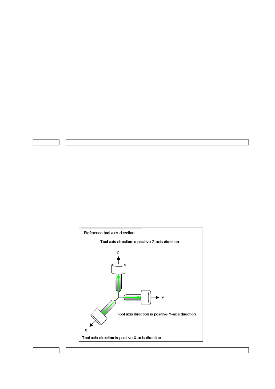
Reference tool axis direction 


[Input type]  Parameter input 


[Data type]  Byte path 

[Valid data range]  0 to 3 

Set  the tool axis direction in the machine coordinate system when the rotation axes for 
controlling the tool are all at 0 degrees.  Also, set the tool axis direction in the machine 
coordinate system in a mechanism in which only the rotation axes for controlling  the 
table are present (there is no rotation axis for controlling the tool). 
1: 

Positive X-axis direction 

2: 

Positive Y-axis direction 

3: 

Positive Z-axis direction 

When the reference tool axis direction is neither the X-, Y-, nor Z-axis direction, set the 
reference direction in this parameter, then set appropriate angles as the reference angle 
RA and reference angle RB (parameters Nos. 19698 and 19699). 


19700 


Rotary table position (X-axis of the basic three axes) 


B-64693EN-1/01


12. PROGRAM COMMAND


- 2227 - 

19701 


Rotary table position (Y-axis of the basic three axes) 


19702 


Rotary table position (Z-axis of the basic three axes) 


[Input type]  Parameter input 


[Data type]  Real path 


[Unit of data]  mm, inch (machine unit) 

[Min. unit of data]  Depend on the increment system of the applied axis 
[Valid data range]  9 digit of minimum unit of data (refer to standard parameter setting table (A)) 

(When the increment system is IS-B, -999999.999 to +999999.999) 
Set these parameters when parameter No. 19680 is set to 12 or 21. The vector from the 
origin of the machine coordinate system to point A on the first rotation axis of the table is 
set as the rotary table position in the machine coordinate system. 


NOTE 


As point A, set a position that is easy to measure on the first rotary 
axis of the table. 


Set a radius value. 


If the rotary table is moved along the X-, Y-, or Z-axis or all of these 
axes, set the position of the rotary table when the machine 
coordinates of the X-, Y-, and Z-axes are all set to 0. 


19703 


Intersection offset vector between the first and second rotation axes of the table   

(X-axis of the basic three axes) 


19704 


Intersection offset vector between the first and second rotation axes of the table   

(Y-axis of the basic three axes) 


19705 


Intersection offset vector between the first and second rotation axes of the table   

(Z-axis of the basic three axes) 


[Input type]  Parameter input 


[Data type]  Real path 


[Unit of data]  mm, inch (machine unit) 

[Min. unit of data]  Depend on the increment system of the applied axis 
[Valid data range]  9 digit of minimum unit of data (refer to standard parameter setting table (A)) 

(When the increment system is IS-B, -999999.999 to +999999.999) 
Set these parameters when the first rotation axis and second rotation axis of the table do 
not intersect. These parameters are valid when parameter No. 19680 is set to 12. When 
the rotation axes for controlling the table are all at 0 degrees, the vector from point A to 
point B on the second rotation axis of the table is set as the intersection offset vector in 
the machine coordinate system. 

12. PROGRAM COMMAND


B-64693EN-1/01


- 2228 - 


NOTE 


As point B, set a position that is easy to measure on the second 
rotary axis of the table. 


Set a radius value. 


19709 


Intersection offset vector between the tool axis and tool rotation axis (X-axis of the basic three axes) 


19710 


Intersection offset vector between the tool axis and tool rotation axis (Y-axis of the basic three axes) 


19711 


Intersection offset vector between the tool axis and tool rotation axis (Z-axis of the basic three axes) 


[Input type]  Parameter input 


[Data type]  Real path 


[Unit of data]  mm, inch (machine unit) 

[Min. unit of data]  Depend on the increment system of the applied axis 
[Valid data range]  9 digit of minimum unit of data (refer to standard parameter setting table (A)) 

(When the increment system is IS-B, -999999.999 to +999999.999) 
Set these parameters when the tool axis and tool rotation axis do not intersect. 
These parameters are valid when parameter No. 19680 is set to 2 or 21. 
If parameter No. 19680 is 21, set the vector from point D on the tool axis to point E 
determined on the tool rotation axis as the intersection offset vector in the machine 
coordinate system when the rotation axes for controlling the tool are all at 0 degrees. 
If parameter No. 19680 is 2, set the vector from point D on the tool axis to point E 
determined on the second rotation axis of the tool as the intersection offset vector in the 
machine coordinate system when the rotation axes for controlling the tool are all at 0 
degrees. 


B-64693EN-1/01


12. PROGRAM COMMAND


- 2229 - 


NOTE 


Point D is determined by adding the tool length offset and tool 
holder offset (parameter No. 19666) to the tool tip. As point E, set a 
position that is easy to measure. 


Set a radius value. 


19712 


Intersection offset vector between the second and first rotation axes of the tool   

(X-axis of the basic three axes) 


19713 


Intersection offset vector between the second and first rotation axes of the tool   

(Y-axis of the basic three axes) 


19714 


Intersection offset vector between the second and first rotation axes of the tool   

(Z-axis of the basic three axes) 


[Input type]  Parameter input 


[Data type]  Real path 


[Unit of data]  mm, inch (machine unit) 

[Min. unit of data]  Depend on the increment system of the applied axis 
[Valid data range]  9 digit of minimum unit of data (refer to standard parameter setting table (A)) 

(When the increment system is IS-B, -999999.999 to +999999.999) 
Set these parameters when the rotation axes of the tool do not intersect. 
These parameters are valid when parameter No. 19680 is set to 2. 
Set the vector from point E on the second rotation axis of the tool to point F on the first 
rotation axis of the tool as the intersection offset vector in the machine coordinate system 
when the rotation axes for controlling the tool are all at 0 degrees. 


NOTE 


As point F, set a position that is easy to measure. 


Set a radius value. 


19741 


Upper limit of the movement range of the first rotation axis 


[Input type]  Parameter input 


[Data type]  Real path 


[Unit of data]  deg 

[Min. unit of data]  Depend on the increment system of the reference axis 

12. PROGRAM COMMAND


B-64693EN-1/01


- 2230 - 

[Valid data range]  9 digit of minimum unit of data (refer to standard parameter setting 

(When the increment system is IS-B, -999999.999 to +999999.999) 
This parameter sets the upper limit of the movement range of the first rotation axis in tool 
axis direction control of the tilted working plane indexing (G53.1). When the movement 
range of the first rotation axis is not specified or the first rotation axis is the roll-over axis, 
this parameter and parameter No. 19742 must both be set to 0. 
 

19742 


Lower limit of the movement range of the first rotation axis 


[Input type]  Parameter input 


[Data type]  Real path 


[Unit of data]  deg 

[Min. unit of data]  Depend on the increment system of the reference axis 
[Valid data range]  9 digit of minimum unit of data (refer to standard parameter setting 

(When the increment system is IS-B, -999999.999 to +999999.999) 
This parameter sets the lower limit of the movement range of the first rotation axis in tool 
axis direction control of the tilted working plane indexing (G53.1). When the movement 
range of the first rotation axis is not specified or the first rotation axis is the roll-over axis, 
this parameter and parameter No. 19741 must both be set to 0. 
 

19743 


Upper limit of the movement range of the second rotation axis 


[Input type]  Parameter input 


[Data type]  Real path 


[Unit of data]  deg 

[Min. unit of data]  Depend on the increment system of the reference axis 
[Valid data range]  9 digit of minimum unit of data (refer to standard parameter setting 

(When the increment system is IS-B, -999999.999 to +999999.999) 
This parameter sets the upper limit of the movement range of the second rotation axis in 
tool axis direction control of the tilted working plane indexing (G53.1). When the 
movement range of the second rotation axis is not specified or the second rotation axis is 
the roll-over axis, this parameter and parameter No. 19744 must both be set to 0. 
 

19744 


Lower limit of the movement range of the second rotation axis 


[Input type]  Parameter input 


[Data type]  Real path 


[Unit of data]  deg 

[Min. unit of data]  Depend on the increment system of the reference axis 
[Valid data range]  9 digit of minimum unit of data (refer to standard parameter setting 

(When the increment system is IS-B, -999999.999 to +999999.999) 
This parameter sets the lower limit of the movement range of the second rotation axis in 
tool axis direction control of the tilted working plane indexing (G53.1). When the 
movement range of the second rotation axis is not specified or the second rotation axis is 
the roll-over axis, this parameter and parameter No. 19743 must both be set to 0. 


12.16.5 

Restrictions of Tilted Working Plane Indexing 

Basic restrictions 


The restrictions imposed on 3-dimensional coordinate conversion also 
apply to the tilted working plane indexing. 


The following presents the restrictions to bear in mind in particular: 


B-64693EN-1/01


12. PROGRAM COMMAND


- 2231 - 

  - 

Increment system 

The same increment system must be used for the basic three axes used by this function. 
 

  - 

Rapid traverse command 

Linear rapid traverse (bit 1 (LRP) of parameter No. 1401=1) must be set for the rapid traverse command. 
 

  - 

3-dimensional coordinate system conversion 

If an attempt is made to set a new coordinate system by performing 3-dimensional coordinate conversion 
in a feature coordinate system, an alarm is also raised. 
 

  - 

Positioning in the machine coordinate system 

Positioning commands in the machine coordinate system such as G28, G30, and G53 operate in the 
machine coordinate system rather than the feature coordinate system. 
 

  - 

External mirror image 

If an attempt is made to use this function and an external mirror image function simultaneously, this 
function takes effect before the external mirror image function. 


Actual path 

Yc 

Xc 

Programmed path 

Feature coordinate system 

Workpiece coordinate system 

Position where mirroring is applied 


Fig. 12.16.5 (a) 


  - 

Tool center point retention type tool axis direction control 

Reset 
Performing a reset during tool center point retention type tool axis direction control results in the 
operation to be performed when the following parameters are set regardless of whether the reset is 
performed in the foreground or background. Thus, do not use the background during tool center point 
retention type tool axis direction control. 
(1)  Bit 2 (D3R) of parameter No. 5400 = 0:  Clears the tilted working plane indexing. 
(2)  Bit 6 (CLR) of parameter No. 3402 = 1:  Clears with a reset. 
(3)  Bit 0 (C08) of parameter No. 3407 = 0:  Clears the G code in group 08. 
(4)  Bit 7 (C23) of parameter No. 3408 = 0:  Clears the G code in group 23. 
(5)  Bit 7 (CFH) of parameter No. 3409 = 0:  Clears the F, H, D, and T codes. 
(6)  Bit 6 (LVK) of parameter No. 5003 = 0:  Clears the tool length compensation vector. 
 
Look-ahead acceleration/deceleration before interpolation 
When using tool center point retention type tool axis direction control, use acceleration/deceleration 
before look ahead interpolation at the same time. If acceleration/deceleration before look ahead 
interpolation is not used, a shock may result. Furthermore, be sure to set the following parameters: 
(1)  Bit 1 (LRP) of parameter No. 1401 = 1:   
 

Linear rapid traverse 

12. PROGRAM COMMAND


B-64693EN-1/01


- 2232 - 

(2)  Bit 5 (FRP) of parameter No. 19501 = 1:   
 

For rapid traverse, uses look-ahead acceleration/deceleration before interpolation. 

(3)  Parameter No. 1671:   
 

Acceleration of acceleration/deceleration for rapid traverse. 

(4)  Parameter No. 1672:   
 

Acceleration change time of look-ahead  bell-shaped acceleration/deceleration before interpolation 
for rapid traverse. 

(5)  Parameter No. 1660:   
 

Maximum permissible acceleration of look-ahead acceleration/deceleration before interpolation. 

If any of these settings is not made, alarm PS5458, "ILLEGAL USE OF G53.1/G53.6", occurs. 
 

  - 

Relationships with other modal commands 

G41, G42, and G40 (cutter compensation), G43, G49 (tool length compensation), G51.1 and G50.1 
(programmable mirror image), and canned cycle commands must have nesting relationships with G68.2. 
In other words, first issue G68.2 when the modes mentioned above are off, turn the modes on and off, 
then issue G69. 
 

  - 

Manual reference position return 

Execution of manual reference position return in the tilted working plane indexing mode issues alarm 
PS5324, “REFERENCE RETURN INCOMPLETE”. Before performing manual reference position return, 
cancel the tilted working plane indexing mode. 
 

  - 

Hypothetical axis of a table rotation axis 

When a table rotation axis is set as a hypothetical axis, tilted working plane indexing is performed on the 
assumption that the table rotation axis is at 0 degrees. 
 

  - 

Specifiable G codes 

The G codes that can be specified in the tilted working plane indexing mode are listed below. 
Specifying a G code other than these codes results in alarm PS5462 “ILLEGAL COMMAND 
(G68.2/G69)”. 

Positioning (G00) 

Linear interpolation (G01) 

Circular interpolation / helical interpolation (G02/G03) 

Dwell (G04) 

AI contour control(G05.1 Q0/Q1) 

Exact stop (G09) 

Programmable data input (G10) 

Tool retract and recover (G10.6) 

Programmable data input mode cancel (G11) 

Plane selection (G17/G18/G19) 

Automatic return to reference position (G28) 

Movement from reference position (G29) 

2nd, 3rd and 4th reference position return (G30) 

Skip function (G31) 

Cutter compensation : cancel (G40) 

Tool radius or tool nose radius compensation (G41/G42) 

Tool length compensation + (G43) 

Tool length compensation - (G44) 

Tool length compensation cancel (G49,G49.1) 

Programmable mirror image cancel (G50.1) 

Local coordinate system (G52) 

Machine coordinate system setting (G53) 

Tool axis direction control (G53.1) 

Workpiece coordinate system selection (G54 to G59, G54.1) 

B-64693EN-1/01


12. PROGRAM COMMAND


- 2233 - 

Exact stop mode (G61) 

Tapping mode (G63) 

Cutting mode(G64) 

Macro call (G65) 

Macro modal call A (G66) 

Macro modal call B (G66.1) 

Macro modal call A/B cancel (G67) 

Canned cycle for drilling (G73, G74, G76, G80 to G89) 

Absolute programming (G90) 

Incremental programming (G91) 

Constant surface speed control (G96) 

Constant surface speed control cancel (G97) 

Canned cycle : return to initial level (G98) 

Canned cycle : return to R point level (G99) 


M


Tool offset increase (G45) 

Tool offset decrease (G46) 

Tool offset double increase (G47) 

Tool offset double decrease (G48) 

Scaling cancel (G50) 

Scaling (G51) 

Programmable mirror image (G51.1) 

Automatic corner override (G62) 

Mode off of coordinate system rotation or 3-dimensional coordinate system conversion (G69) 

Inverse time feed (G93) 

Feed per minute (G94) 

Feed per revolution (G95) 


T


Mode off of coordinate system rotation or 3-dimensional coordinate system conversion (G69.1) 

Feed per minute (G98 (G94)) 

Feed per revolution (G99 (G95)) 


  - 

Modal G codes that allow specification of a tilted working plane indexing 

A tilted working plane indexing can be specified in the modal G code states listed below. 
In a modal state other than the following modal G codes, specifying the tilted working plane indexing 
results in alarm PS5462 “ILLEGAL COMMAND (G68.2/G69)”: 

Positioning (G00) 

Linear interpolation (G01) 

Programmable data input mode cancel (G11) 

Plane selection (G17/G18/G19) 

Polar coordinates command cancel (G15) 

Input in inch (G20 (G70)) 

Input in mm (G21 (G71)) 

Stored stroke check function (G22/G23) 

Cutter compensation : cancel (G40) 

Tool length compensation cancel (G49,G49.1) 

Programmable mirror image cancel (G50.1) 

Workpiece coordinate system selection (G54 to G59, G54.1) 

Exact stop mode (G61) 

Tapping mode (G63) 

Cutting mode (G64) 

Macro modal call A/B cancel (G67) 


Content      ..     282      283      284      285     ..