FANUC Series 0i-MODEL F Plus. CONNECTION MANUAL (FUNCTION) - page 260
 

  Index      Manuals     FANUC Series 0i-MODEL F Plus. CONNECTION MANUAL (FUNCTION) B-64693EN-1/01


Search            copyright infringement  


Content      ..     258      259      260      261     ..


FANUC Series 0i-MODEL F Plus. CONNECTION MANUAL (FUNCTION) - page 260


12. PROGRAM COMMAND


B-64693EN-1/01


- 2034 - 


[Input type]  Setting input 


[Data type]  Bit 


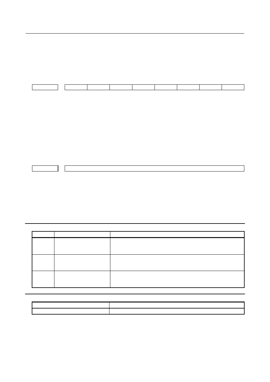
#1  CTV

  Character counting for TV check in the comment section of a program. 

0: 

Performed 

1: 

Not performed 


#7 

#6 

#5 

#4 

#3 

#2 

#1 

#0 

3201 


NPE 

N99 


[Input type]  Parameter input 


[Data type]  Bit path 


#5  N99

  With an M99 block, when bit 6 (NPE) of parameter No. 3201 is set to  0, program 

registration is assumed to be: 
0: 

Completed 

1: 

Not completed 


#6  NPE

  With an M02, M30, or M99 block, program registration is assumed to be: 

0: 

Completed 

1: 

Not completed 


6030 


M code to execute external device subprogram calls 


[Input type]  Setting input 


[Data type]  2-word path 

[Valid data range]  0 to 99999999 

Set the M code to execute external device subprogram calls. When 0 is set, M198 is used. 
M01, M02, M30, M98, and M99 cannot be used to execute external device subprogram 
calls. When a negative number, 1, 2, 30, 98, or 99 is set for this parameter, M198 is used 
to execute external device subprogram calls. 
 

Alarm and message 

Number 

Message 

Description 

SR0001 

TH ERROR 

A TH error was detected during reading from an input device. 
The read code that caused the TH error and how many statements it is 
from the block can be verified in the diagnostics screen. 

SR0002 

TV ERROR 

An error was detected during the single–block TV error. 
The TV check can be suppressed by setting bit 0 (TVC) of parameter 
No. 0000 to 0. 

PS5010 

END OF RECORD 

The EOR (End of Record) code is specified in the middle of a block. 
This alarm is also generated when the percentage at the end of the NC 
program is read. 


Reference item 

Manual name 

Item name 

OPERATOR’S MANUAL (B-64694EN) 

PROGRAM CONFIGURATION 


B-64693EN-1/01


12. PROGRAM COMMAND


- 2035 - 

12.4 

PART PROGRAM STORAGE SIZE / NUMBER OF 
REGISTERABLE PROGRAMS


The following table lists the combinations of program storage sizes and the total number of registerable 
programs. 

Part program storage 

size 

Number of registerable 

programs expansion 1 

2Mbyte 

1000 


NOTE 

1  Creating one folder results in the 

number of programs yet to be 
registerable decreasing one. 

2  The program storage size means 

the maximum size of a program if 
the program is the one and only 
program registered. 

3  If more than one program is 

registered, the total size of 
registerable programs reduces for 
the following reason. 
The FS0

i

-F Plus manage programs 

in page units. The unit of program 
storage is managed also in page 
units. When a program is created, 
as many pages as necessary to 
store the program are secured, and 
the program is stored on these 
pages. Generally, the last program 
storage page has an unused area 
(Fig. 13.4). This unused area cannot 
be used to store any other program. 
For the sake of program 
management, it is regarded as an 
area in use. 
The FS0

i

- C uses a similar way of 

management, but the unit of pages 
in it differs from that in the FS0

i

-F 

Plus. So, if more than one program 
is registered in the FS0

i

-F Plus, the 

total program size of registerable 
programs in the FS0

i

-F Plus differs 

from that in the FS0

i

-C. 


Reference item 

Manual name 

Item name 

OPERATOR’S MANUAL (B-64694EN) 

Program management 


Example of creating program O0001 

O0001 ; 
N1 G01  ; 

M30 ; 

First page 

Second page 

Last page 

Program O0001 

Unusable for any other 
program 

(Area in use) 

N100 … ; 

(Area in use) 

(Area in use) 

(Unused area) 

Fig. 13.4   

12. PROGRAM COMMAND


B-64693EN-1/01


- 2036 - 

12.5 

INCH/METRIC CONVERSION 

Overview 

Either inch or metric input (least input increment) can be switched by the following five methods. 

G code(G20/G21) 

SETTING (HANDY) screen/setting bit 2 (INI) parameter No. 0000 

PMC Window 

Programable parameter input(G10) 

Custom macro variable #3005 


Explanation 

  - 

Switching method using a G code(G20/G21) 

The unit of input data is switched by G20/G21. It switches to inch input by G20, and metric input by G21. 
Please refer to the OPERATOR'S MANUAL (Common to Lathe System/Machining Center 
System)(B-64694EN) for switching conditions of G20/G21. 
 

Switching method using a SETTING (HANDY) screen/setting parameter 

The unit of input data is switched by SETTING (HANDY) screen or setting bit 2 (INI) parameter   
No.  0000.  Please refer to the OPERATOR'S MANUAL (Common to Lathe System/Machining Center 
System)(B-64694EN) for switching conditions. 
 

Switching method using a PMC Window 

The unit of input data is switched by writing setting data of PMC window (low speed type). Please refer 
to the PMC Programming Manual (B-64513EN) for details. 
 

Switching method using a programable parameter input(G10) 

Setting  bit 2 (INI) parameter No.  0000  is rewritten by the G10 command, and the unit of input data is 
switched. 
 

Switching method using a custom macro variable 

The unit of input data is switched by system variable #3005. 
 

Switching position   

The unit of input data is switched at the reference position of the machine coordinate system origin. When 
the bit 1 (INAx) of parameter No. 14000 set to 1,  if an inch-metric switch command is executed at a 
position other than the machine coordinate system origin (position = zero), the  alarm PS5362, 
“CONVERT INCH/MM AT REF-POS” is generated. 
 

In case G code(G20/G21), it is possible to change the unit at the positions other than 0 of the 
machine coordinate by the following settings. 

(a)  Setting bit 2 (IRFx) of parameter No. 14000 to 1 enables inch/metric conversion to be performed in 

the reference position (parameter No. 1240).  However,  enable a function of workpiece coordinate 
system (bit 0 (NWZ) of parameter No. 8136 is 0). 

(b)  Setting bit 0 (NIM) of parameter No. 11222 enables inch/metric conversion to be performed even in 

positions other than the reference position.  However,  enable  functions  of workpiece coordinate 
system and workpiece coordinate system preset (bit 0 (NWZ) of parameter No. 8136 is 0 and bit 1 
(NWC) of parameter No. 8136 is 0). 


In case SETTING (HANDY) screen or setting parameter or PMC Window, it is possible to change 
the unit at the positions other than 0 of the machine coordinate by the following settings. 

B-64693EN-1/01


12. PROGRAM COMMAND


- 2037 - 

(c)  Setting bit 0 (NIM) of parameter No. 11222 enables inch/metric conversion to be performed even in 

positions other than the reference position.  However,  enable  functions  of workpiece coordinate 
system and workpiece coordinate system preset (bit 0 (NWZ) of parameter No. 8136 is 0 and bit 1 
(NWC) of parameter No. 8136 is 0). 

(d)  Setting bit 0 (NIM) of parameter No. 11222 and  bit  3  (IMRx) of parameter No. 14000  enables 

inch/metric conversion to limit in  the reference position (parameter No. 1240).  However,  enable 
functions of workpiece coordinate system and workpiece coordinate system preset (bit 0 (NWZ) of 
parameter No. 8136 is 0 and bit 1 (NWC) of parameter No. 8136 is 0). 


Table 12.5 (a)  The position that inch / metric conversion can be changed by G code(G20/G21)


Parameter No. 

Position that can be changed 

14000 

11222 

Reference point 

(parameter No. 1240) 

Other than the 

reference 

position 

#1(INAx) 

#2(IRFx) 

#3(IMRx) 

#0(NIM) 

=0 


Changed 

Not changed 

Not changed 

Changed 

Not changed

 (*1)


Not changed

 (*1)


Changed 

Changed 

Not changed

 (*1)


Changed 

Changed 

Changed 

Changed 

Changed 

Not changed

 (*1)


(*1) Alarm(PS5362) 


Table 12.5 (b)  The position that inch / metric conversion can be changed by SETTING (HANDY) screen or   

setting parameter or PMC Window


Parameter No. 

Position that can be changed 

14000 

11222 

Reference point 

(parameter No. 1240) 

Other than the 

reference 

position 

#1(INAx) 

#2(IRFx) 

#3(IMRx) 

#0(NIM) 

=0 


Changed 

Not changed 

Not changed 

Changed 

Not changed

 (*1)


Not changed

 (*1)


Changed 

Not changed 

Not changed

 (*1)


Changed 

Changed 

Changed 

Changed 

Changed 

Not changed

 (*1)


(*1) Alarm(PS5362) 


Signal 

Inch input signal INCH<Fn002.0> 

  [Classification]  Output signal 
 

[Function]  This signal informs that inch input mode is active. 


[Output cond.]  1indicates that the inch input mode (G20) is in progress, and 0 indicates that metric input 

mode (G21) is in progress. 


NOTE 


This signal changes to the corresponding state when the following 
methods. 

- SETTING (HANDY) screen/setting bit 2 (INI) parameter No. 0000. 
- Parameter INI is rewritten by Programable parameter input (G10) 
- System variable #3005 


12. PROGRAM COMMAND


B-64693EN-1/01


- 2038 - 

Signal address 


#7 

#6 

#5 

#4 

#3 

#2 

#1 

#0 

Fn002 


INCH 


Parameter 


#7 

#6 

#5 

#4 

#3 

#2 

#1 

#0 

0000 


INI 


[Input type]  Setting input 


[Data type]  Bit path 


#2  INI

  Unit of input 

0: 

In metrics 

1: 

In inches 


#7 

#6 

#5 

#4 

#3 

#2 

#1 

#0 

1001 


INM 


[Input type]  Parameter input 


[Data type]  Bit path 


NOTE 


When this parameter is set, the power must be turned off before 
operation is continued. 


#0  INM

  Least command increment on the linear axis 

0: 

In mm (metric system machine) 

1: 

In inches (inch system machine) 


#7 

#6 

#5 

#4 

#3 

#2 

#1 

#0 

1006 


ROSx 

ROTx 


[Input type]  Parameter input 


[Data type]  Bit axis 


NOTE 


When at least one of these parameters is set, the power must be 
turned off before operation is continued. 


#0  ROTx 


#1  ROSx 

   Setting linear or rotary axis. 

ROSx 

ROTx 

Meaning 

Linear axis 
(1)  Inch/metric conversion is done. 
(2)  All coordinate values are linear axis type. (Is not rounded in 0 to 360

°

(3)  Stored pitch error compensation is linear axis type (Refer to parameter No. 

3624) 

B-64693EN-1/01


12. PROGRAM COMMAND


- 2039 - 

ROSx 

ROTx 

Meaning 

Rotary axis (A type) 
(1)  Inch/metric conversion is not done. 
(2)  Machine coordinate values are rounded in 0 to 360

°

. Absolute coordinate 

values and relative coordinate values can be selected without rounding / 
rounding according to bits 0 (ROAx) and 2 (RRLx) of parameter No. 1008. 

(3)  Stored pitch error compensation is the rotation type. (Refer to parameter 

No. 3624) 

(4)  Automatic reference position return (G28, G30) is done in the reference 

position return direction and the move amount does not exceed one 
rotation. 

Rotary axis (B type) 
(1)  Inch/metric conversion is not done. 
(2)  Machine coordinate values, absolute coordinate values and relative 

coordinate values are linear axis type. (Is not rounded in 0 to 360

°

). 

(3)  Stored pitch error compensation is linear axis type (Refer to parameter No. 

3624) 

(4)  Cannot be used with the rotary axis roll-over function and the index table 

indexing function (M series) 

Except for the 

above. 

Setting is invalid (unused) 


1240 


Coordinate value of the reference position in the machine coordinate system 


NOTE 


When this parameter is set, the power must be turned off before 
operation is continued. 


[Input type]  Parameter input 


[Data type]  Real axis 


[Unit of data]  mm, inch, deg (machine unit) 

[Min. unit of data]  Depend on the increment system of the applied axis 
[Valid data range]  9 digit of minimum unit of data (refer to standard parameter setting table (A)) 

(When the increment system is IS-B, -999999.999 to +999999.999) 
Set the coordinate values of the reference position in the machine coordinate system. 


#7 

#6 

#5 

#4 

#3 

#2 

#1 

#0 

3104 


MCN 


[Input type]  Parameter input 


[Data type]  Bit path 


#0  MCN

  Machine position 

0: 

Regardless of whether input is made in mm or inches, the machine position is 
displayed in mm for millimeter machines, or in inches for inch machines. 

1: 

When input is made in mm, the machine position is displayed in mm, and when 
input is made in inches, the machine position is displayed in inches accordingly. 


#7 

#6 

#5 

#4 

#3 

#2 

#1 

#0 

3405 


AUX 


[Input type]  Parameter input 


[Data type]  Bit path 

12. PROGRAM COMMAND


B-64693EN-1/01


- 2040 - 


#0  AUX

  When the second auxiliary function is specified in the calculator-type decimal point input 

format or with a decimal point, the multiplication factor for a value output (onto the code 
signal) relative to a specified value is such that: 
0: 

The same multiplication factor is used for both of metric input and inch input. 

1: 

A multiplication factor used for inch input is 10 times greater  than that used for 
metric input. 

 
When the second auxiliary function is specified in the calculator-type decimal point input 
format or with a decimal point, the value output onto the code signal is a specified value 
multiplied by a value indicated below. 

Increment system 

Parameter AUX=0 

Parameter AUX=1 

Metric 
input 
system 

IS-A for reference axis 

100 times 

100 times 

IS-B for reference axis 

1000 times 

1000 times 

IS-C for reference axis 

10000 times 

10000 times 


Inch input 
system 

IS-A for reference axis 

100 times 

1000 times 

IS-B for reference axis 

1000 times 

10000 times 

IS-C for reference axis 

10000 times 

100000 times 


#7 

#6 

#5 

#4 

#3 

#2 

#1 

#0 

11222 


IMG 

CIM 

NIM 


[Input type]  Parameter input 


[Data type]  Bit path 


#0  NIM

  Automatic conversion of a coordinate system by an inch/metric conversion command 

(G20 or G21) is: 
0: 

Not performed. 

1: 

Performed. 


#1  CIM

  When an inch/metric conversion command (G20 or G21) is specified, if the workpiece 

coordinate system is shifted by the shift amount as described below: 
0: 

An alarm PS1298”ILLEGAL INCH/METRIC CONVERSION” is issued. 

1: 

Clearing of the shift amount is performed. 

 
If bit 0 (NIM) of parameter No. 11222 is set to 1, or if bit 2 (IRF) of parameter No. 14000 
is set to 1, this parameter clears the following: 

Manual intervention made when the manual absolute signal*ABSM<Gn006.2>  is 
off 

Issuance of a move command with the machine locked 

Movement by handle interrupt 

Operation with a mirror image 

Shifting of a workpiece coordinate system when a local coordinate system or 
workpiece coordinate system is set up 


#2  IMG

  Inch/metric conversion is: 

0: 

Performed with the G20/G21 (G70/G71). 

1: 

Not performed with the G20/G21 (G70/G71). 


B-64693EN-1/01


12. PROGRAM COMMAND


- 2041 - 

NOTE 

If bit 2 of parameter No. 11222 is 1 (inch/metric conversion with 

G20/G21 is disabled), only bit 2 of parameter No. 0 can be used to 
perform inch/metric conversion. If bit 2 of parameter No.0 = 0, the 
metric system is used. If bit 2 of parameter No.0 = 1, the inch 
system is used. 


#7 

#6 

#5 

#4 

#3 

#2 

#1 

#0 

14000 


IMRx 

IRFx 

INAx 


[Input type]  Parameter input 


[Data type]  Bit axis 


NOTE 


When this parameter is set, the power must be turned off before 
operation is continued. 


#1  INAx

  If an inch-metric switch command is  executed at a  position of the machine coordinate 

system origin other than zero, 
0: 

No alarm is issued. 

1: 

Alarm PS5362, “CONVERT INCH/MM AT REF-POS” is issued. 


#2  IRFx

  An inch-metric switch command (G20, G21) at the reference position is: 

0: 

Disabled. 

1: 

Enabled. 


NOTE 

1  When this function is enabled for an axis, if an attempt to switch 

between the inch and metric unit is made although the tool is not at 
the reference position on that axis, an alarm PS5362 is issued, and 
switching between the inch and metric unit is canceled. Be sure to 
move the tool to the reference position by, for example, specifying 
G28 before switching between the inch and metric unit. 

2  This function enables the inch/metric switching commands (G20 and 

G21) at the reference position. It does not enable the switching of the 
setting input unit (bit 2 (INI) of parameter No.0000). 

3  Switching between inch and metric by setting the setting input unit 

(bit 2 (INI) of parameter No. 0000) is enabled only when the machine 
coordinate of the first reference position is 0 (parameter No. 1240 is 
0) and presence on the first reference position is assumed. For a 
system in which the machine coordinate of the first reference position 
is not 0, set this parameter to 1 and specify G20/G21 in the first 
reference position to switch between inch and metric. 

4  When this function is disabled, the switching is enabled only when 

the machine coordinate of the first reference position is 0 (parameter 
No. 1240 is 0) and presence on the first reference position is 
assumed. 


#3  IMRx

  When bit 0 (NIM) of parameter No.11222 is set to 1, the reference position return before 

commanding inch/metric conversion : 
0: 

Not required. 

1: 

Required. 


Content      ..     258      259      260      261     ..