FANUC Series 0i-MODEL F Plus. CONNECTION MANUAL (FUNCTION) - page 245
 

  Index      Manuals     FANUC Series 0i-MODEL F Plus. CONNECTION MANUAL (FUNCTION) B-64693EN-1/01


Search            copyright infringement  


Content      ..     243      244      245      246     ..


FANUC Series 0i-MODEL F Plus. CONNECTION MANUAL (FUNCTION) - page 245


11. TOOL FUNCTIONS


B-64693EN-1/01


- 1914 - 

NOTE 

1  When G50 X_Z_T_ ; is specified, the tool is not moved. 
 

The coordinate system in which the coordinate value of the tool position is (X,Z) is 
set. The tool position is obtained by subtracting the offset value corresponding to 
the tool offset number specified in the T code. 

2  The G codes in the 00 group other than G50 must not be specified in the same 

block as that containing a T code. If any one of G28, G29, G30, and G53 is 
specified in the same block together with a T code, alarm PS0245, "T-CODE NOT 
ALLOWED IN THIS BLOCK", is issued. 

 
  - 

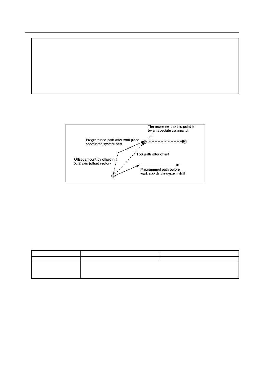
Compensation with coordinate shift 

The work coordinate system is shifted by the X, Y, and Z tool offset amounts. Namely, the offset amount 
corresponding to the number designated with the T code is added to or subtracted from the absolute 
coordinates. 


Fig. 11.1.3 (b) Offset operation with coordinate shift 


  - 

Starting and canceling offset by specifying a T code 

Specifying a tool offset number with a T code means to select the tool offset value corresponding to it and 
to start offset. Specifying 0 as a tool offset number means to cancel offset. 
For offset with tool movement, whether to start or cancel the offset can be specified with bit 6 (LWN) of 
parameter No. 5002. 
For compensation with coordinate shift, the offset is started and canceled when a T code is specified. For 
the cancellation of geometry compensation, its operation can be selected with bit 5 (LGC) of parameter 
No. 5002. 
 

Table 11.1.3 (b) 

Compensation method 

Bit 6 (LWN) of parameter No. 5002=0 

Bit 6 (LWN) of parameter No. 5002=1 

Tool movement 

When a T code is specified 

When an axial movement is specified 

Coordinate shift 

When a T code is specified 

(Note that geometry compensation can be canceled only if bit 5 (LGC) of parameter 

No. 5002 = 1.) 


  - 

Canceling offset with reset 

Tool offset is canceled under one of the following conditions: 
<1>  The power to the CNC is turned off and turned back on 
<2>  The reset button on the MDI unit is pressed 
<3>  A reset signal is input from the machine to the CNC 
In cases <2> and <3> above, it is possible to select a cancel operation using bits 3 (LVC) of parameter No. 
5006 and 7 (TGC) of parameter No. 5003. 
 

B-64693EN-1/01


11. TOOL FUNCTIONS


- 1915 - 

Table 11.1.3 (c) 

Compensation method 

Parameter 

LVC=0 

TGC=0 

LVC=1 

TGC=0 

LVC=0 

TGC=1 

LVC=1 

TGC=1 

Tool 

movement 

Wear compensation 

Not 

canceled. 

Canceled. 

(When axial movement 

is specified) 

Not 

canceled. 

Canceled. 

(When axial movement 

is specified) 

Geometry compensation 

Coordinate 

shift 

Wear compensation 

Not 

canceled. 

Canceled. 

Not 

canceled. 

Canceled. 

Geometry compensation 

Not 

canceled. 

Not canceled. 

Canceled. 

Canceled. 


Notes and restrictions 

Helical interpolation (G02, G03) 


Tool position offset cannot be specified in a block in which helical interpolation is used. 

Coordinate system rotation (G68.1) 


Coordinate system rotation is executed on the command program first, followed by tool position 
offset. 

3-dimensional coordinate conversion (G68.1) 


If tool position offset is used, tool position offset with coordinate shift cannot be used. Offset with 
tool movement must be specified inside a nest of 3-dimensional coordinate conversion.  At the 
beginning block of the 3-dimensional coordinate conversion, tool does not move for a converted tool 
offset value. 


Example) 


G68.1 ... ;


T0101; 


  :


T0100; 


G69.1 ... ; 


Workpiece coordinate system preset (G50.3) 


When the bit 7(WTC) of parameter No.1205 is 0, performing workpiece coordinate system preset 
causes tool position offset with tool movement to be canceled; this does not cause tool position 
offset with coordinate shift to be canceled. 


When the bit 7(WTC) of parameter No.1205 is 1, performing workpiece coordinate system preset 
does not cause  neither  tool position offset with tool movement nor  tool position offset with 
coordinate shift to be canceled. 

Machine coordinate system setting (G53), reference position return (G28), second, third, and fourth 
reference position return (G30), and manual reference position return 

 
Basically, before performing these commands or operations, cancel tool position offset. These operations 
do not cause tool position offset to be canceled. The actions in the Table 11.1.3 (d) take place: 
 

Table 11.1.3 (d)   


When the command or operation is 

specified 

When the next axial movement command 

is specified 

Tool movement 

The tool offset value is temporarily canceled. 

The tool offset value is reflected. 

Coordinate shift 

Coordinates with the tool offset value 
reflected are assumed. 

Coordinates with the tool offset value 
reflected are assumed. 


Arbitrary speed threading   


The alarm PS0528, “THREADING FORMAT ERROR” is issued when a T-code and the M-code for 
starting arbitrary speed threading are specified in the same block. 


11. TOOL FUNCTIONS


B-64693EN-1/01


- 1916 - 

Auxiliary function output in moving axis (G50.9)   


The alarm PS5330, “G50.9 FORMAT ERROR”  is issued  when a T-code and auxiliary function 
output in moving axis (G50.9) are specified in the same block. 


Programmable parameter input (G10)   


The alarm PS1144, “G10 FORMAT ERROR”  is issued when a T-code is specified during 
programmable parameter input. 


Parameter 


#7 

#6 

#5 

#4 

#3 

#2 

#1 

#0 

1205 


WTC 


[Input type]  Parameter input 


[Data type]  Bit path 


#7  WTC

  When workpiece coordinate system preset is done, actual tool position offset by tool 

movement is : 
0: 

Not considered. 

1: 

Considered. 


3032 


Allowable number of digits for the T code 


[Input type]  Parameter input 


[Data type]  Byte path 

[Valid data range]  1 to 8 

Set the allowable numbers of digits for the T codes. 
When 0 is set, the allowable number of digits is assumed to be 8. 


#7 

#6 

#5 

#4 

#3 

#2 

#1 

#0 

3129 


DAP 

DRP 


[Input type]  Parameter input 


[Data type]  Bit path 


#0  DRP

  For relative coordinate display: 

0: 

The actual position considering a tool offset (tool movement) is displayed. 

1: 

The programmed position excluding a tool offset (tool movement) is displayed. 


#1  DAP

  For absolute coordinate display: 

0: 

The actual position considering a tool offset (tool movement) is displayed. 

1: 

The programmed position excluding a tool offset (tool movement) is displayed. 


#7 

#6 

#5 

#4 

#3 

#2 

#1 

#0 

3290 


GOF 

WOF 


[Input type]  Parameter input 


[Data type]  Bit path 


#0  WOF

  Setting the tool offset value (tool wear offset) by MDI key input is: 

0: 

Not disabled. 

1: 

Disabled.  (With parameters  Nos. 3294 and 3295, set the offset  number range in 
which updating the setting is to be disabled.) 

B-64693EN-1/01


11. TOOL FUNCTIONS


- 1917 - 


NOTE 


When tool offset memory A is selected with the M series, the tool 
offset set in this parameter WOF is followed even if geometric 
compensation and wear compensation are disabled (bit 6 (NGW) of 
parameter No. 8136 is set to 1) with the T series. 


#1  GOF

  Setting the tool geometry offset value by MDI key input is: 

0: 

Not disabled. 

1: 

Disabled.  (With parameters  Nos. 3294 and 3295, set the offset  number range in 
which updating the setting is to be disabled.) 


3294 


Start number of tool offset values whose input by MDI is disabled 


3295 


Number of tool offset values (from the start number) whose input by MDI is disabled 


[Input type]  Parameter input 


[Data type]  Word path 

[Valid data range]  0 to 999 

When the modification of tool offset values by MDI key input is to be disabled using bits 
0 (WOF) and 1 (GOF) of parameter No. 3290, parameters Nos. 3294 and 3295 are used to 
set the range where such modification is disabled. In parameter No. 3294, set the offset 
number of the start of tool offset values whose modification is disabled. In parameter No. 
3295, set the number of  such values. In the following cases, however, none of the tool 
offset values may be modified: 

When 0 or a negative value is set in parameter No. 3294 

When 0 or a negative value is set in parameter No. 3295 

When a value greater than the maximum tool offset number is set in parameter No. 
3294 

In the following case, a modification to the values ranging from the value set in parameter 
No. 3294 to the maximum tool offset number is disabled: 

When the value of parameter No. 3294 added to the value of  parameter No. 3295 
exceeds the maximum tool offset number 

When the offset value of a prohibited number is input through the  MDI panel, the 
warning "WRITE PROTECT" is issued. 


[Example]  When the following parameter settings are made, modifications to  both of the tool 

geometry offset values and tool wear offset values corresponding to offset numbers 51 to 
60 are disabled: 

Bit 1 (GOF) of parameter No. 3290 = 1 (to disable tool geometry  offset value 
modification) 

Bit 0 (WOF) of parameter No. 3290 = 1 (to disable tool wear  offset value 
modification) 

Parameter No. 3294 = 51 

Parameter No. 3295 = 10 

If the setting of bit 0 (WOF) of parameter No. 3290 is set to 0 without  modifying the 
other parameter settings above, tool geometry offset value modification only is disabled, 
and tool wear offset value modification is enabled.   
 

11. TOOL FUNCTIONS


B-64693EN-1/01


- 1918 - 


#7 

#6 

#5 

#4 

#3 

#2 

#1 

#0 

5002 


WNP 

LWM 

LGC 

LGT 

ETC 

LWT 

LGN 


[Input type]  Parameter input 


[Data type]  Bit path 


#1  LGN

  Geometry offset number of tool offset : 

0: 

Is the same as wear offset number 

1: 

Specifies the geometry offset number by the tool selection number 


NOTE 


This parameter is valid when tool geometry/wear compensation is 
enabled (bit 6 (NGW) of parameter No.8136 is 0). 


#2  LWT

  Tool wear compensation is performed by: 

0: 

Moving the tool. 

1: 

Shifting the coordinate system. 


NOTE 


This parameter is valid when tool geometry/wear compensation is 
enabled (bit 6 (NGW) of parameter No.8136 is 0). 


#3  ETC

  When a T-code command is two digits or shorter, the T code is: 

0: 

Not extended. 

1: 

Extended. 

When this parameter is 1, two-digit or shorter T-code commands are extended. 
(Three-digit or longer T-code commands are not extended.) The value after extension is 
determined by the setting of the number of digits in the offset number in T-code 
commands (parameter No. 5028). 
 

Parameter No. 

5028


Number of digits after 

extension 

Sample extension 

Extended to two digits 

Before extension: T1 

 After extension: T11 

Extended to four digits 

Before extension: T1 

 After extension: T0101 

3 or greater 

Not extended 

 
[Example] 

Parameter No. 5028 : 2 

Parameter No. 3032 : 4 (Allowable number of digits in T code)


Before extension 


After extension 

T1 


T0101 (1-digit command is extended to 4 digits.) 

T12 


T1212 (2-digit command is extended to 4 digits.) 

T112 


T112 (Not extended) 

T1122 


T1122 (Not extended) 


NOTE 

1  The setting of the allowable number of digits in T code (parameter 

No. 3032) indicates the number of digits in a specified command 
(before being extended). If the number of digits in the command 
exceeds the allowable number of digits in T code, the alarm 
PS0003, “TOO MANY DIGIT” is issued. 

B-64693EN-1/01


11. TOOL FUNCTIONS


- 1919 - 

NOTE 

2  This parameter is dedicated to the lathe system. Tool change is 

available with the turret type setting (bit 3 (TCT) of parameter No. 
5040 = 0). 

3  If the number of digits in the offset number in a T-code command 

(parameter No. 5028) is set to 0, the value after extension is 
determined by the number of digits in the number of tool 
compensation values (parameter No. 5024). 

4  Common variable #149 for calling a T-code macro is set to the 

pre-extension value. 


#4  LGT

  Tool geometry compensation is: 

0: 

Compensated by the shift of the coordinate system 

1: 

Compensated by the tool movement 


NOTE 


This parameter is valid when tool geometry/wear compensation is 
enabled (bit 6 (NGW) of parameter No.8136 is 0). 


#5  LGC

  When tool geometry compensation is based on coordinate shifting, the tool geometry 

offset is: 
0: 

Not canceled by a command with offset number 0. 

1: 

Canceled by a command with offset number 0. 


NOTE 


This parameter is valid when tool geometry/wear compensation is 
enabled (bit 6 (NGW) of parameter No.8136 is 0). 


#6  LWM

  Tool offset operation based on tool movement is performed: 

0: 

In a block where a T code is specified. 

1: 

Together with a command for movement along an axis. 


#7  WNP

  Imaginary tool tip number used for tool nose radius compensation, when the tool 

geometry/wear compensation function is equipped, is the number specified by: 
0: 

Geometry offset number   

1: 

Wear offset number 


#7 

#6 

#5 

#4 

#3 

#2 

#1 

#0 

5003 


TGC 


[Input type]  Parameter input 


[Data type]  Bit path 


#7  TGC

  A tool geometry offset based on a coordinate shift is: 

0: 

Not canceled by reset. 

1: 

Canceled by reset. 


NOTE 


This parameter is valid when tool geometry/wear compensation is 
enabled (bit 6 (NGW) of parameter No.8136 is 0). 


11. TOOL FUNCTIONS


B-64693EN-1/01


- 1920 - 


#7 

#6 

#5 

#4 

#3 

#2 

#1 

#0 

5004 


ORC 


[Input type]  Parameter input 


[Data type]  Bit path 


#1  ORC

  The setting of a tool offset value is corrected as: 

0: 

Diameter value 

1: 

Radius value 


NOTE 


This parameter is valid only for an axis based on diameter 
specification. For an axis based on radius specification, specify a 
radius value, regardless of the setting of this parameter. 


#7 

#6 

#5 

#4 

#3 

#2 

#1 

#0 

5006 


LVC 


TGC 


[Input type]  Parameter input 


[Data type]  Bit 


#1  TGC

  If a T code is specified in a block where G50, G04, or G10 is specified: 

0: 

No alarm is issued. 

1: 

The alarm PS0245, “T-CODE NOT ALLOWED IN THIS BLOCK” is issued. 


#3  LVC

  A tool offset (geometry/wear) based on a tool movement and wear offset based on a 

coordinate shift are: 
0: 

Not canceled by reset. 

1: 

Canceled by reset. 


5013 


Maximum value of tool wear compensation 


[Input type]  Parameter input 


[Data type]  Real path 


[Unit of data]  mm, inch (offset unit) 

[Min. unit of data]  The increment system of a tool offset value is followed. 
[Valid data range]  The settings of bits 3 to 0 (OFE, OFD, OFC, and OFA) of parameter No. 5042 are 

followed. 

For metric input 

OFE 

OFD 

OFC 

OFA 

Valid data range 

0 to 9999.99mm 

0 to 9999.999mm 

0 to 9999.9999mm 

0 to 9999.99999mm 

0 to 999.999999mm 


For inch input 

OFE 

OFD 

OFC 

OFA 

Valid data range 

0 to 999.999inch 

0 to 999.9999inch 

0 to 999.99999inch 

0 to 999.999999inch 

0 to 99.9999999inch 


B-64693EN-1/01


11. TOOL FUNCTIONS


- 1921 - 

This parameter sets the maximum allowable tool wear compensation value. If an attempt 
is made to set a tool wear compensation value, the absolute value of which exceeds the 
value set in this parameter, the following alarm or warning is output: 

Input from MDI 

Warning: DATA IS OUT OF RANGE 

Input by G10 

Alarm PS0032: ILLEGAL OFFSET VALUE IN G10. 

When 0 or a negative value is set, no maximum allowable value is applied. 


[Example]  When 30.000 is set 

As a tool offset value, a value from -30.000 to +30.000 can be input. 
 

5014 


Maximum value of incremental input for tool wear compensation 


[Input type]  Parameter input 


[Data type]  Real path 


[Unit of data]  mm, inch (offset unit) 

[Min. unit of data]  The increment system of a tool offset value is followed. 
[Valid data range]  The settings of bits 3 to 0 (OFE, OFD, OFC, and OFA) of parameter No. 5042 are 

followed. 

For metric input 

OFE 

OFD 

OFC 

OFA 

Valid data range 

0to9999.99mm 

0to9999.999mm 

0to9999.9999mm 

0to9999.99999mm 

0to999.999999mm 


For inch input 

OFE 

OFD 

OFC 

OFA 

Valid data range 

0to999.999inch 

0to999.9999inch 

0to999.99999inch 

0to999.999999inch 

0to99.9999999inch 

 
Set the maximum allowable value for the tool wear compensation value, input as an 
incremental value. If the incremental input value (absolute value) exceeds the set value, 
the following alarm or warning message is output: 

Input from MDI 

Warning: DATA IS OUT OF RANGE 

Input by G10 

Alarm PS0032: ILLEGAL OFFSET VALUE IN G10. 

When 0 or a negative value is set, no maximum allowable value is applied. 
 

5024 


Number of tool compensation values 


NOTE 


When this parameter is set, the power must be turned off before 
operation is continued. 


[Input type]  Parameter input 


[Data type]  Word path 

[Valid data range]  0 to 999 

Set the maximum allowable number of tool compensation values used for each path. 
Ensure that the total number of values set in parameter No. 5024 for the individual paths 
is within the number of compensation values usable in the entire system. The number of 
compensation values usable in the entire system depends on the option configuration. 


Content      ..     243      244      245      246     ..