FANUC Series 0i-MODEL F Plus. CONNECTION MANUAL (FUNCTION) - page 240
10. SPINDLE SPEED FUNCTION
B-64693EN-1/01
- 1874 -
Limitation
-
If an analog spindle motor is used, the spindle may fail to rotate at a specified speed depending on
the type of the spindle motor and the resolution of the spindle motor drive amplifier with respect to
the speed command voltage, and the spindle motor-to-spindle speed reduction ratio.
-
High-precision spindle speed control is invalid for rigid tapping S commands. If a command with a
decimal point is issued, the command is assumed to specify an integer (with the fraction rounded
off).
-
The M type gear selection method is unusable.
-
The Manual Guide
i
is unusable.
10.24
SIMPLE SPINDLE ELECTRONIC GEAR BOX
Overview
This function executes spindle synchronous control between two serial spindles based on input signals so
that one spindle (slave spindle) follows the other spindle (master spindle). It uses a method of referencing
directly feedback pulses to enable the slave spindle to follow fluctuations in the master spindle speed with
a small error, thereby achieving high-precision spindle synchronous control.
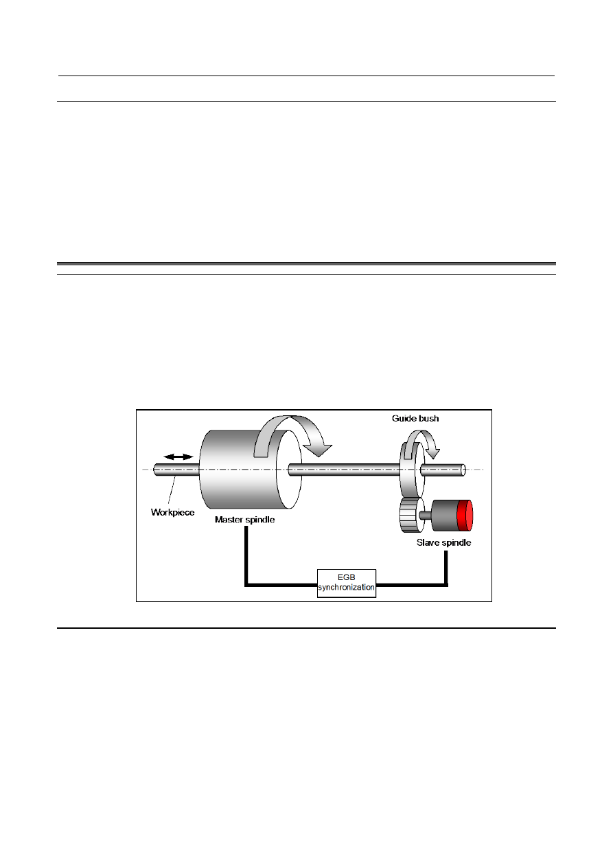
An example of using the function might be rotary guide bush control where two spindles are used.
An electronic gear box (hereafter called EGB) for the spindle is used to make the two spindles
synchronize with each other.
Using the function requires enabling the spindle serial output (bit 5 (SSN) of parameter No.8133 is 0) and
the Cs contour control (bit 2 (SCS) of parameter No.8133 is 1).
Fig. 10.24 (a) Application example
Specification
With the spindle EGB, the synchronous pulse is produced from the feedback pulse output by the position
detector attached to the master axis, and the slave axis rotates according to the synchronous pulse. The
feedback pulse sent from master spindle to the slave spindle is forwarded by communication between
spindle amplifiers.
This function uses the PMC input signal to turn the simple spindle EGB mode ON/OFF.
Turning on the simple spindle EGB mode ON does not impose any limitation to the spindle control mode
for the master spindle. However, the slave spindle must be in the Cs contour control mode.
During the simple spindle EGB mode, the coordinates of the slave spindle are not updated even if the
slave spindle moves in synchronization with the master spindle.
The simple spindle EGB needs the same spindle system configuration (motor, amplifier, and sensor) as
the spindle EGB. For details, see the Item, “Spindle EGB (spindle electronic gear box)” in the FANUC